Instruction for Dynafix base for CMM 3R-770.6-1 / 3R-770.46-1
System 3R International AB © I-814-E 02.12 Subject to modifications 7
Closing and opening sequence with air gun
1. Release enclosed air pressure in Turbo
chamber, with a finger or other aid, by pressing
the valve at connection ”Turbo” (2) for Dynafix
and (12) for chuck in center.
2. Air gun is pressed to the inlet valve at
connection ”Unclamp” (1) for Dynafix and (11)
for chuck in center, at a duration of a few
seconds. Springload in valve will ensure that
built up air pressure will be enclosed.
3. Change the pallet.
4. Release enclosed air pressure in Unclamp
chamber, with a finger or other aid, by pressing
the valve at connection ”Unclamp” (1) for
Dynafix and (11) for chuck in center. The
springloaded piston is activated and clamp the
pallet in chuck.
5. Air gun is pressed to the inlet valve at
connection ”Turbo” (2) for Dynafix and (12) for
chuck in center, at a duration of a few seconds.
Springload in valve will ensure that built up air
pressure will be enclosed.
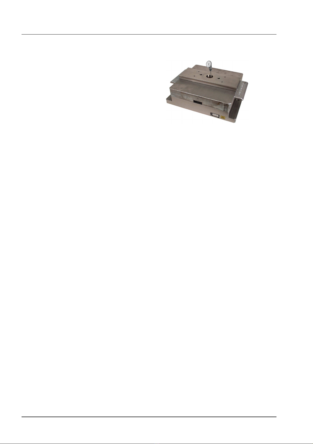
Ventilation
The table chuck is provided with a hole (E), which
function as a channel to the chuck. The ventilation
holes should be unplugged to let any overpressure
out during measuring operation.
Sealing (A)
The chuck is provided with a sealing (A) around its
periphery. The sealing seals against the pallet, so
that liquid cannot come in between the table chuck
and the pallet. The table chuck must be dried.