System Sensor IST200 User manual

D500-50-00 Pittway Tecnologica S.r.l, Via Caboto 19/3, 34147 Trieste, Italy I56-2629-004
1
2
6
7
8
9
3
45
11
22
(+)
(-)
(+)
(-)
BEFORE INSTALLING
This information is included as a quick reference installation guide. Refer to the control
panel installation manual for detailed system information. If the IST200 will be installed in
an existing operational system, inform the operator and local authority that the system will
be temporarily out of service. Disconnect power to the control panel before installing
the IST200.
GENERAL DESCRIPTION
The IST200 Translator Module is intended for use in analogue addressable systems in
conjunction with System Sensor 22051EISE and 2251EIS intrinsically safe smoke sensors.
The IST200 Translator serves as an interface between the control panel and up to 15 of the
above sensors. It must be used in conjunction with the Y72221 Galvanic Isolator Barrier.
SPECIFICATIONS
Input Voltage (V in): 15 to 32 VDC
Output Voltage: 20 to 24 VDC
Input Current: 17mA @ V in = 15V, 9.7mA @ V in = 24V
Short circuit output current: 7.6mA Maximum
Operating Temperature Range: 0°C to 60°C
Operating Humidity Range: 5 to 95%RH
Maximum 22051EISE / 2251EIS sensors: 15
NOTE:Input currents assume there are no wiring faults and that the IST200 is loaded per
the panel manufacturer’s instructions.
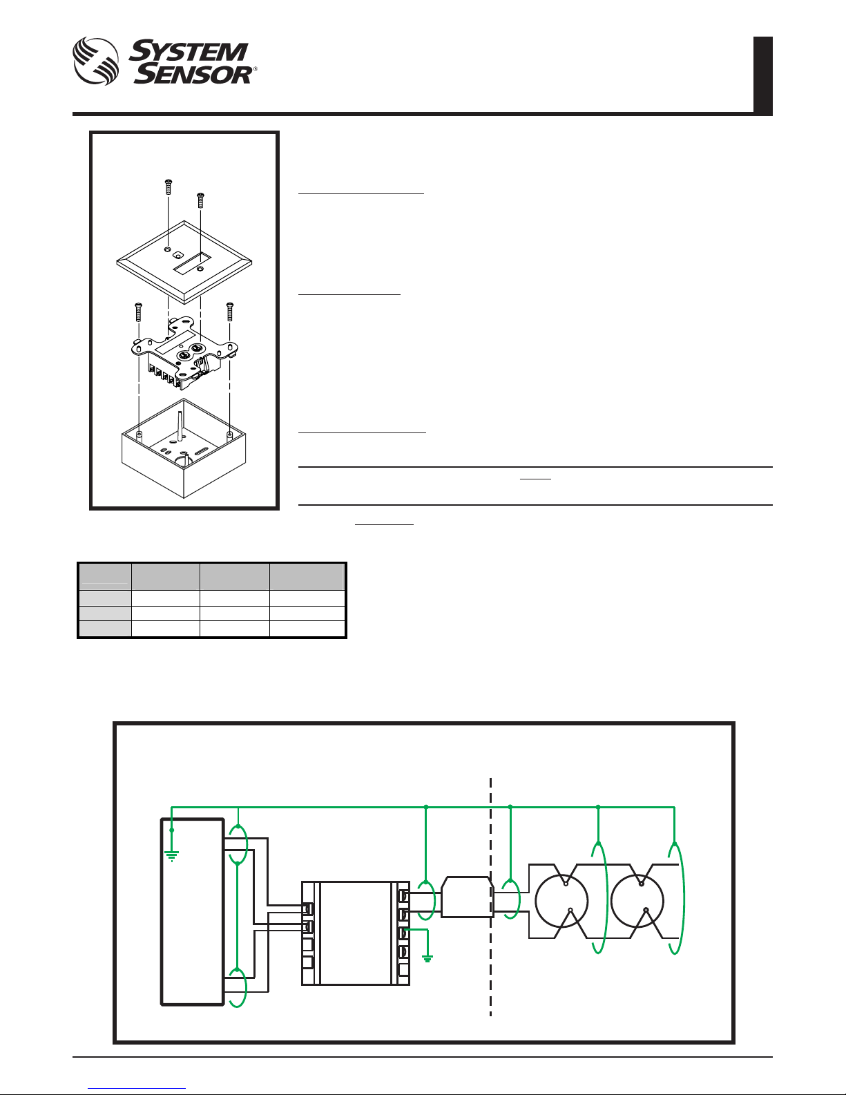
MOUNTING IST200 DEVICES
The IST200 mounts directly to a 100mm square electrical box with a minimum depth of
54mm, such as the SMB500 as shown in Figure 1.
INSTALLATION AND MAINTENANCE INSTRUCTIONS
MODEL IST200 INTELLIGENT SYSTEM TRANSLATOR
For Use With Models 22051EISE & 2251EIS
Intrinsically Safe Smoke Sensor
WIRING
Notes:All wiring must conform to applicable local codes and regulations.
The IST200 translator must be mounted in a suitable electrical box.
The capacitance and inductance or inductance/resistance (L/R) ratio of
the cable connected to the hazardous area between the B501AP power
terminals (1 and 2) must not exceed the values indicated in Table 1.
1. See Figure 2 for wiring details.
2. Loop wiring from control panel to the IST200 should be shielded, and the
shield connected to ground only at the control panel. Cable from the IST200
to the barrier can be shielded, but if so, the shield should not be connected
directly to ground, but either left floating or connected to the loop input cable
shield. Cable from the barrier to the sensors can be shielded but if so, the
shield must not be connected to ground.
3. Secure translator to SMB500 mounting box as shown in Figure 1.
Table 1: Maximum Permissible Capacitance,
Inductance and Impedance Figures Across
Terminals 1 and 2 on a B501AP Base
Figure 1: IST200 Mounting in
SMB500 Surface Mount Box
SAFE AREA HAZARDOUS AREA
Y72221
Galvanic
Isolator
Figure 2: Wiring of IST200 Translator Module with Y72221 Galvanic Isolator and 22051EISE
(or 2251EIS) Intrinsically Safe Smoke Sensor Mounted in a B501AP Sensor Base
Control
Panel
Loop earth connects to the panel earth at one end of loop only
22051EISE
+ B501AP
IST200 Translator
Module
22051EISE
+ B501AP
IST200 earth
connection must
be connected
directly to earth
Cable screens Must Not be
connected to IST200 terminal 7
IST200
Group Capacitance
µF
Inductance
mH
L/R Ratio
µH/Ohm
IIC
0.083 4.2 55
IIB
0.65 12.6 210
IIA
2.15 33.6 444
(+)
(-)
(+)
(-)
11(+) (+)1
12(-) (-)2
ENGLISH
D500-50-00 Pittway Tecnologica S.r.l, Via Caboto 19/3, 34147 Trieste, Italy I56-2629-004
110 mm
107.5 mm
12 3
45 6
789
10 11 12
20 mm
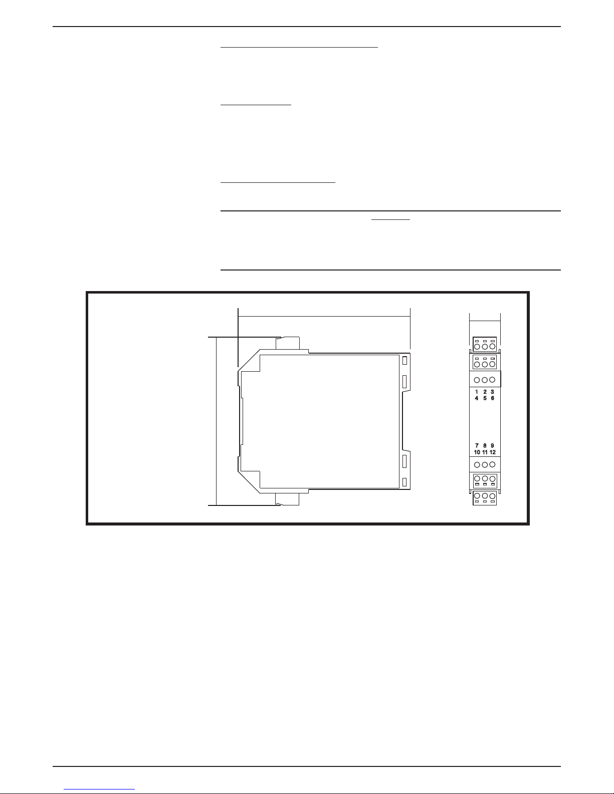
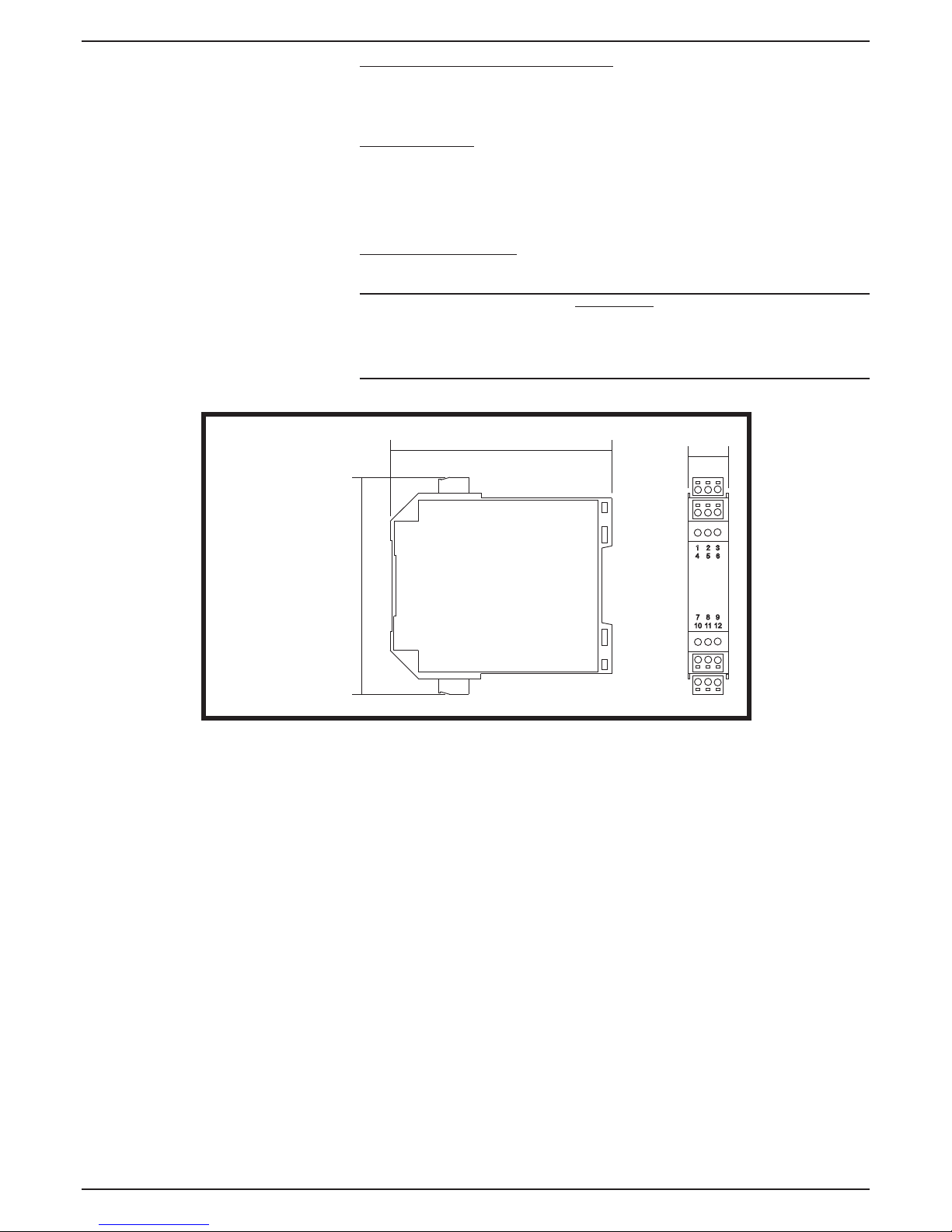
MODEL Y72221 GALVANIC ISOLATORS
The Y72221 is a single channel transformer isolated repeater especially designed and
manufactured by Pepperl and Fuchs for use as an intrinisically safe isolator between the
IST200 translator module and up to 15 22051EISE and 2251EIS optical smoke sensors.
The Y72221 is certified intrinsically safe EEx ia IIC.
SPECIFICATIONS
Voltage Range: Input (Safe Side) 20 to 24VDC
Output (To Hazardous Area) 0.6 to 24VDC
Current Range: 1 to 20mA
Short Circuit Current (Output): 65mA maximum
Working Temperature Range: -20°C to 60°C
Weight: 100g approx
INSTALLATION AND WIRING
The Y72221 should be mounted inside a suitable enclosure in the safe area. See Figures
2 and 3 for wiring details.
CAUTION
Y72221 Galvanic isolators comprise part of an intrinsically safe system for use in
potentially flammable atmospheres, and must be installed in accordance with all
appropriate international, national and local standard codes of practice and site
regulations for intrinsically safe apparatus.
Figure 3:Y72221 Galvanic
Isolator IS Barrier
D500-50-00 Pittway Tecnologica S.r.l, Via Caboto 19/3, 34147 Trieste, Italy I56-2629-004
1
2
6
7
8
9
3
45
11
22
(+)
(-)
(+)
(-)
INSTRUCCIONES DE INSTALACIÓN Y MANTENIMIENTO
DEL MÓDULO IST200 ANALÓGICO CONVERTIDOR DE
PROTOCOLO PARA LOS DETECTORES DE SEGURIDAD
INTRÍNSECA 22051EISE Y2251EIS
CABLEADO
Notas: Todas las conexiones deben cumplir con las normas, ordenanzas y códigos locales.
El IST200 se debe montar en una caja de conexiones adecuada.
La capacidad e inductancia o la relación inductancia/resistencia (L/R) del cable
conectado a la zona de riesgo entre los terminales de alimentación (1 y 2) de
B501AP no debe superar los valores indicados en la tabla 1.
1. Véase la figura 2 si desea más detalles sobre las conexiones.
2. El cable de lazo de la central al módulo IST200 debe ser apantallado y la pantalla se
debe conectar a tierra solo en la central. El cable desde el IST200 al aislador galvánico
puede ser apantallado, pero, si es así, la pantalla no debe conectarse directamente a
tierra, sino dejarse suelta o conectada a la pantalla del cable de entrada del lazo. El
cable desde el aislador a los sensores puede ser apantallado, pero la pantalla tampoco
debe conectarse a tierra.
3. Fije la caja de montaje SMB500 tal y somo se ilustra en la figura 1.
Tabla 1: Valores máximos de capacidad, inductancia e
impedancia en los terminales 1 y 2 de una base B501AP.
Fig. 1: Montaje del IST200 en
una caja SMB500 para montaje
en superficie.
Figura 2: Conexión del módulo IST200 con el aislador galvánico Y72221 y el detector de
humo seguridad intrínseca 22051EISE (o 2251EIS) montado en una base B501AP.
(+)
(-)
(+)
(-)
11(+) (+)1
12(-) (-)2
La pantalla del lazo se conecta a la
central solo en un extremo del lazo
Módulo convertidor
IST200
ÁREA SEGURA ÁREA DE RIESGO
Aislador
galvánico
Y72221
22051EISE
+ B501AP
22051EISE
+ B501AP
La conexión a
tierra del IST200
debe conectarse
directamente a
tierra.
Las pantallas de cable NO se
deben conectar al terminal 7
del IST200.
IST200
Grupo Capacidad
µF
Inductancia
mH
Relación L/R
µH/Ohm
IIC
0.083 4.2 55
IIB
0.65 12.6 210
IIA
2.15 33.6 444
Esta información es una guía de referencia rápida para la instalación del módulo IST200. Si desea
información más detallada, consulte el manual de la central de incendios. Si el módulo IST200 se instala
en un sistema ya operativo, informe a la empresa y autoridades competentes de que el sistema estará
temporalmente fuera de servicio. Desconecte la alimentación de la central antes de instalar el módulo.
DESCRIPCIÓN GENERAL
El módulo convertidor IST200 se utiliza en los sistemas direccionables y analógicos junto con los
detectores de humo ópticos de seguridad intrínseca 22051EISE y 2251EIS. El módulo IST200 sirve
como interfaz entre la central de incendios y hasta 15 detectores 22051EISE / 2251EIS. Se debe utilizar
junto con el aislador galvánico Y72221.
Para garantizar un funcionamiento correcto, el IST200 solo se debe conectar a centrales de incendio
compatibles.
ESPECIFICACIONES
Tensión de entrada: de 15 a 32 Vcc
Tensión de salida: de 20 a 24 Vcc
Corriente de entrada: 17mA a V (entrada) = 15V, 9,7mA a V (entrada) = 24V
Corriente de salida de cortocircuito: 7,6mA máximo
Temperatura de funcionamiento: de 0°C a 60°C
Humedad de funcionamiento: de 5 a 95% HR
Nº máximo de detectores 22051EISE / 2251EIS: 15
NOTA: Los valores de corriente de entrada se refieren a corrientes sin averías en el cableado y con el
IST200 alimentado según las instrucciones del fabricante de la central.
MONTAJE DE LOS IST200
El IST200 se monta directamente en una caja de conexiones cuadrada de 100mm de ancho x 54mm de
fondo, como la SMB500 ilustrada en la fig. 1.
AVISO
Desconecte la alimentación del lazo antes de instalar el IST200.
Central de
incendios
ESPAÑOL
D500-50-00 Pittway Tecnologica S.r.l, Via Caboto 19/3, 34147 Trieste, Italy I56-2629-004
110 mm
107.5 mm
12 3
45 6
789
10 11 12
20 mm
AISLADORES GALVÁNICOS MODELO Y72221
El Y72221 es un aislador galvánico de un único canal diseñado y fabricado por Pepperl and Fuchs
para utilizarse como aislador de seguridad intrínseca entre el módulo convertidor IST200 y hasta un
máximo de 15 detectores de humo ópticos 22051EISE y 2251EIS. El Y72221 dispone del certificado
de seguridad intrínseca EEx ia IIC.
ESPECIFICACIONES
Rango de tensión: Entrada (área segura) de 20 a 24Vcc
Salida (a zona de riesgo) de 0,6 a 24Vcc
Rango de corriente: de 1 a 20mA
Corriente de cortocircuito (Salida): 65mA máximo
Temperatura de funcionamiento: de -20°C a 60°C
Peso: 100g aprox.
INSTALACIÓN Y CABLEADO
El Y72221 debe montarse dentro de una carcasa adecuada en el área segura. Véase las figuras 2
y 3 si desea detalles sobre las conexiones.
PRECAUCIÓN
Los aisladores galvánicos Y72221 forman parte de un sistema de seguridad intrínseca para
atmósferas potencialmente inflamables y deben instalarse de acuerdo a los requisitos de las
normativas, códigos de práctica y reglamentos locales, nacionales e internacionales para
aparatos de seguridad intrínseca.
Figura 3: Aislador
galvánico Y72221
Table of contents
Languages:


