SyxthSense FCU2001 User manual

FCU2001 and SY100 Digital Interface
Engineering Guide
Copyright ©2004 Syxthsense Ltd
All rights reserved.

Online Store: www.syxthsense.com Copyright ©2004 SyxthSense Ltd.
Enquiries: T: 0870 20 80 100 F: 0870 20 80 200 FCU2001 and SY100 Engineering Guide 2
Copyright Notice
This document has been prepared by SyxthSense Limited using (i) its own proprietary information
and (ii) proprietary information owned and controlled by other third parties (for which SyxthSense
Limited has a right to use). The contents are copyrighted and must not be communicated in whole
or in part to any other party without the prior written approval of SyxthSense Limited.
SyxthSense Limited has prepared this document in good faith based on information made available
to it by third party contributors. SyxthSense reserves the right to make amendments and to correct
any errors that are identified herein without notice.
Nothing in this document nor in any related discussions or correspondence shall be construed as an
offer, nor the basis of any contract, nor a representation which may be relied upon by any person
except as SyxthSense Limited may expressly agree in writing.
The following notice applies to this document and shall be reproduced on any permitted copies:
© 2003 SyxthSense Limited. All rights reserved.
Any request for further information concerning this document should be addressed to:
SyxthSense Limited
Gibbs House
Kennel Ride
Ascot SL5 7NT
United Kingdom.

Online Store: www.syxthsense.com Copyright ©2004 SyxthSense Ltd.
Enquiries: T: 0870 20 80 100 F: 0870 20 80 200 FCU2001 and SY100 Engineering Guide 3
Contents
CHAPTER 1 INTRODUCTION 4
CHAPTER 2 FUNCTIONS 5
TURNING THE CONTROLLER ON/OFF...............................................................................................................5
CONTROLLING THE TEMPERATURE.................................................................................................................5
THE WINDOW CONTACT ...............................................................................................................................5
CONTROL OF THE FAN...................................................................................................................................5
CONTROL OF THE VALVES .............................................................................................................................6
CONTROL OF OCCUPANCY.............................................................................................................................6
BOOST MODE ................................................................................................................................................7
INTRUDER ALARMS.......................................................................................................................................7
ALARM OF OPEN WINDOW .............................................................................................................................7
BATHROOM ALARM ......................................................................................................................................8
CHAPTER 3 PROGRAMMING OF THE FCU2001 9
PROGRAMMING OF THE ADDRESS OF THE CONTROLLER ..................................................................................9
PROGRAMMING OF THE REST OF PARAMETERS ...............................................................................................9
THE CONTROLLER ADDRESS .......................................................................................................................10
P-0 APPLICATION TWO OR FOUR PIPES........................................................................................................10
P-1 SUMMER/WINTER OR BY ENTRANCE .....................................................................................................10
P-2 LIMTED OR FREE SET POINT POINT .......................................................................................................11
P-3 OPERATION IN STANDBY.......................................................................................................................11
P-4 MINIMUM VENTILATION.......................................................................................................................11
P-5 CONTROL OF PRESENCE........................................................................................................................11
P-6 HIDDEN ROOM TEMPERATURE..............................................................................................................11
P-7 SUMMER/WINTER.................................................................................................................................11
P-8 WINDOW CONTACT..............................................................................................................................12
P-9 BATHROOM ALARM..............................................................................................................................12
CHAPTER 4 COMMISSIONING AND MAINTENANCE CHECKS13

Online Store: www.syxthsense.com Copyright ©2004 SyxthSense Ltd.
Enquiries: T: 0870 20 80 100 F: 0870 20 80 200 FCU2001 and SY100 Engineering Guide 4
Chapter 1
Introduction
The system is made up of two components, the control unit and the display module.
These two parts are connected by a 3 core screened cable no greater than 10 meters
long.
The FCU 2001, is the control unit, this can be located inseide an electrical enclosure or
on the Fan-coil unit itself adjaecent to the power supply and valve connections. The FCU
2001 can be stand alone with a display or it can be networked to a central BMS system
either with or without a display.
The SY 100 display has two key roles, it is used to permit engineering of the controller
and to prvide simple local changes to the ambient conditions by the room occupant post
engineering. The SY interface can be adapted to suit the decoration of the room by
selecting the appropriate colour/finish of the outer clip on covers. These are available
from SyxthSense ltd.

Online Store: www.syxthsense.com Copyright ©2004 SyxthSense Ltd.
Enquiries: T: 0870 20 80 100 F: 0870 20 80 200 FCU2001 and SY100 Engineering Guide 5
Chapter 2
Functions
TURNING THE CONTROLLER ON/OFF
The Fan-coil can be enabled and be disabled in two ways:
1. By means of the keyboard. Pressing On/Off we enable the Fan-coil. The Air conditioning is
disabled by pressing the On/Off button once more.
2. By means of communications. We can enale/disable the Fan-coil by using the
communications link to a BMS. We can read the state of the equipment, alarms and also
the room temperature back to the front end. We can re-program the controller if required
The BMS control is useful in two ways:
In facilities that wish to maintain the air conditioning of the rooms when the client leaves we can
guarantee that this controller stays active. For it will activate the room controller too meet the
required set point. This option is similar to our P3 function (see X).
In facilities that have a need to control the total consumed energy, it can be interesting to disable
the conditioned air momentarily, to reduce peaks of consumption. In this case we will disable the
controller.
CONTROLLING THE TEMPERATURE
The FCU 2001 measures the room temperature by means of the sensor located in the return duct
of the Fan-coil. Based on this temperature the controller will enable the appropriate heating or
cooling valve and modulate the fan speed to suit the conditions and the occupancy schedule via the
BMS. Adapting the speed of the fan automatically increasing comfort and reducing temperature
errors as quickly as possible.
THE WINDOW CONTACT
If a magnetic contact of window in connected across terminals 22-23 (contact closed with closed
window), when this opens it initiates a timing of 10 seconds (adjustable by communications), after
this delay, the Fan-coil will be stopped and the valves closed until the window is closed again, at
which moment the FCU will start again.
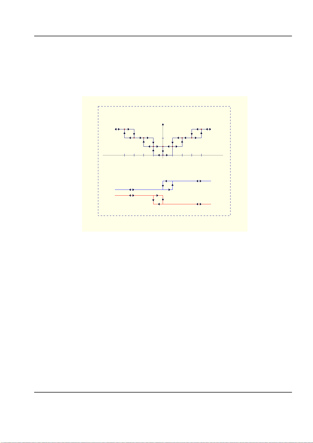
CONTROL OF THE FAN
When activating the air conditioning, by means of the On/Off button the controller will start at
manual speed one. The speed can be modified manually acting on the fan speed control. This
speed will stay independently of the environmental conditions.
If the controller is in the Automatic position, LED automatic On/Off, the speed will automatically
adjust based on the error with respect to the set point. The greater the error then the greater the
speed of the fan. When the dead zone nearest to the selected set point is reached, the fan will be

Online Store: www.syxthsense.com Copyright ©2004 SyxthSense Ltd.
Enquiries: T: 0870 20 80 100 F: 0870 20 80 200 FCU2001 and SY100 Engineering Guide 6
stopped or it will remain in the first speed, based on the way of operation selected by the
configuration of P-4.
In the following graph we show how the fan speed and valves are adapted according to the to the
measured temperature.
As th fan speed changes, the relays of the controller are delayed by an interval of approximately 2
seconds to avoid possible short circuits in the fan motor.
V. III
V. II
V. I
+0.5ºC
+1.0ºC
+1.5ºC
+2.0ºC
P. consigna
-0.5ºC
-1.0ºC
-1.5ºC
-2.0ºC
Válvula Fría
Válvula Caliente
Comportamiento Regulador
CONTROL OF THE VALVES
When the measured temperature is away from the set point by more than ±0.5ºC the controller will
open the cooling or heating valve and it will remain open until the temperature reaches the set point
again. At the same time the fan will start up according to the previously described mode of
operation.
The valve behaviour is based on the P-0 setting which determines the type of installation of 4 or 2
pipe control.
CONTROL OF OCCUPANCY
The control of occupancy can be established of two ways (To see program number 5):
Card Key entrance. We detect presence if we have a room card in a wall socket used by most hotel
chains. When the card is removed a count down begins, (120 sec. adjustable by communications)
to turn the FCU off based on the fact that the room key has been removed from the key slot by the
entrance.
PIR/Door Exit/Entry. By means of a contact monitoring the door or doors determines if the room is
occupied. (PIR’s must be connected normally closed in series) This way of determination of the
presence is not exact since many factors can occur meaning that more than one person could be in
the room or could have left.

Online Store: www.syxthsense.com Copyright ©2004 SyxthSense Ltd.
Enquiries: T: 0870 20 80 100 F: 0870 20 80 200 FCU2001 and SY100 Engineering Guide 7
It is for that reason that the alarm functions are stopped. An intrusion via a window being opened in
conjunction with a PIR can set an alarm if requested to the BMS, the central booking system can
activate this automatically by communications from the central computer, forcing the state of
occupancy and guaranteeing the correct operation of the alarms.
The air conditioning may be disabled when not occupied by the central booking system on all
events even when the door is opened by the cleaners.
The application as well as the ventilation and the general the behaviour of the Fan-coil changes
based on the determination of a presence. The correct programming of the Fan-coil is therefore
dependant on a correct understanding of the different options that the equipment supports.
BOOST MODE
In some situations e.g. night operation, abandonment of room with the air conditioning working,
etc... the setpoint can be controlled from the BMS to place greater influence over the setpoint more
so than can be achieved via the local interface.
The BMS can force the controller into a boost mode thus placing a maximum effect on the control
loop. This override mode is not held in RAM and therefore the controller will not stay in this mode
should the controller suffer a power loss.
The boost setpoint will be used for as long as the controller is in this mode. The boost set point can
lie outside of the user adjustable limits.
Additional functions of the FCU 2001 controller.
The FCU 2001 has several additional functions that have a time delay influence over the air
conditioning these are:
• detection of intruders
• window opening
• absence of a presence in the room.
INTRUDER ALARMS.
When enabled outside of the set operating times the alarm will be generated.
ALARM OF OPEN WINDOW
The opening of the window will cause a maintained alarm. This will allow security staff to close the
window in case of storms or if it has been left opened during the cleaning of the premises. This
information will stay until we erase the indication by communications, or we must make sure that the
alarm is no longer active.

Online Store: www.syxthsense.com Copyright ©2004 SyxthSense Ltd.
Enquiries: T: 0870 20 80 100 F: 0870 20 80 200 FCU2001 and SY100 Engineering Guide 8
BATHROOM ALARM
The bathroom alarm will activate independent of the state of the Fan-coil. The activation of the
contact will raise the alarm. This information will stay until we remove the indication by
communications, or we must make sure that the alarm is not active. This function could also be
used for a maid call or do not enter status in different applications

Online Store: www.syxthsense.com Copyright ©2004 SyxthSense Ltd.
Enquiries: T: 0870 20 80 100 F: 0870 20 80 200 FCU2001 and SY100 Engineering Guide 9
Chapter 3
Programming of the FCU2001
Once power has been supplied to the controller it will need to be programmed. This is carried out
via the SY100 interface
• Sop the Fan-coil by means of the On/Off button.
• Pess the button marked with a Fan then jointly press the On/Off button simultaneously, hold for
3 seconds.
PROGRAMMING OF THE ADDRESS OF THE CONTROLLER
The assigned number of the controller will be displayed.
Pressing On/Off we will happen to modify the units. This will be marked appearing the point decimal
on them. With arrows +/- we can increment/decrement the units until the required number is shown.
If you are happy with the number set the press “On/Off” again to store this first value.
If you wish to change to “tens” press the Fan button once more.
In the tens range we will have the same procedure, only that the decimal point will be located in this
area. In order to change to hundreds press the “Fan” button and the to finish press “On/Off”.
In the hundreds exactly the same. With the Fan button we will enter again to the units and we will
finish with On/Off.
PROGRAMMING OF THE REST OF PARAMETERS
Unlike the address of the controller, the rest of parameters that establish the way of operation of
FCU 2001, only can take values “N2 (No) or “S” (Set) and the programming style is similar to the
one previously described for the address.
10 programmable parameters exist, P-0 to P-9 whose meaning is detailed in the attached table.
Program Description. Default. Value
Controller Bus Address 001 001
P0 Type of application, 2 or 4 pipe 2 tubes N
P1 Summer/Winter or by entrance. According to P7 N
P2 Limited set point. Limited. N
P3 Operation in Standby. Off N
P4 Minimum speed in automatic. No fan. N
P5 Control of Presence. Room Key Socket N
P6 Hidden temperature on SY display Visible temperature on
SY display N
P7 State of Winter, single if P1 = N Summer. N
P8 Contact of window No .not used N
P9 Contact bathroom alarm No .not used N
P0.- N=2 pipe ; S=4 pipe
P1.- N=P7 ; S= Entrance

Online Store: www.syxthsense.com Copyright ©2004 SyxthSense Ltd.
Enquiries: T: 0870 20 80 100 F: 0870 20 80 200 FCU2001 and SY100 Engineering Guide 10
P2.- N=Limited to ±3 ; S= between +5 to +30
P3.- N=Unemployment if it is not present at ; S=Do not stop fan
P4.- N= For ventilator; S= It does not stop ventilator
P5.- N=Key Socket ; S= Magnetic Contact + PIR
P6.- N=See the Space Temp on the SY display ; S=Not See the Space Temp on the SY display
P7.- N= Summer ; S= Winter
P8.- N=No contact ; S=Contact
P9.- N=No contact ; S=Contact
If the engineering mode is not exited correctly by pressing the Fan buttion and after 30 seconds the
controller will go back into auto control and engineering mode will be stopped. The controller will
return automatically to normal controller without any stored changes.
THE CONTROLLER ADDRESS
The address for the communications. The established protocol is Modbus RTU of the Modicon
series.
We must consider four aspects:
1. – There cannot be two controllers with the same address on the same LAN of communications.
2. - Address 000 is reserved to send a generic message (Broadcast) to all of the controllers.
Therefore the units begin in 001.
3. - This data could not be changed by communications.
4. - By hardware considerations, we have a commitment between immunity and number of
controllers placed on the same LAN, the maximum number of controllers is limited to 127 units.
P-0 APPLICATION TWO OR FOUR PIPES
Value N indicates an installation to 2 tubes. This is the value by default.
Value S indicates an installation to 4 tubes.
In case from installation to 2 tubes, the valve can be connected indifferently to anyone of the two
outputs.
The contacts of the valves relays are normally open.
P-1 SUMMER/WINTER OR BY ENTRANCE
Value N indicates change of regime by P-7 or by communications. It is the value by default.
Value S indicates change of regime through a switched Entrance (Terminals 24-25)
This function can be used when the change of Summer/Winter regime wants to centralise even
though does not exist communication bus. In this P-1 case it will be programmed with value S and
the signal of regime to the logical entrance will be connected. In this case closing the contact of this
one entrance, interprets like regime of summer and regime of winter when the contact is open.

Online Store: www.syxthsense.com Copyright ©2004 SyxthSense Ltd.
Enquiries: T: 0870 20 80 100 F: 0870 20 80 200 FCU2001 and SY100 Engineering Guide 11
P-2 LIMTED OR FREE SET POINT POINT
Value N indicates set point limited to ±3ºC on the predefined values. It is the value by defect.
Value S indicates adjustable free set point between +5ºC and +30ºC.
The set point can be modified pressing on the buttons Up and Down, in steps of 0.5ºC. the set
point, by default is 20ºC, whereas in Winter it happens to 24ºC. Both can be modified voluntarily
through the Bus.
P-3 OPERATION IN STANDBY
Value N sets unemployment of the Fan-coil when the client leaves the room. It is the value by
default
Value S respectively causes the increase/reduction of the set points of summer/winter, when the
client leaves the room. This supposes that the Fan-coil works exactly just as if the client remains in
the room but with the modified set point to work to.
This single operation has sense in facilities to 2 tubes, since if we have 4, the controller in summer
would activate the heating when leaving the room, and in winter it would activate the conditioned air
The value of the increments/reduction can be modified voluntarily through the Bus of
Communication, being a value by default of 3ºC.
P-4 MINIMUM VENTILATION
Value N causes unemployment of the Fan-coil 1 minute after reaching the desired temperature. It is
this value by default.
Value S causes that it does not stop the Fan-coil when the valve has been closed, maintaining a
minimum ventilation in speed.
P-5 CONTROL OF PRESENCE
Value N defines the control of presence by connected room key switch or to terminals 20-21. It is
this value by default
Value S defines the control of presence by magnetic contact in the front door, (terminals
20-21) along with volumetric detectors (terminals 18-19).
P-6 HIDDEN ROOM TEMPERATURE
Value N qualifies the representation of the temperature in display. The set point visualises of
intermittent form when pressing the keys above or down and during 3 seconds. It is this value by
default.
Value S hides to the temperature, allowing the display to show only the set point
P-7 SUMMER/WINTER
Value N sets the operating conditions to be Summer. It is this value by default.
Value S defines the operating conditions to be Winter.

Online Store: www.syxthsense.com Copyright ©2004 SyxthSense Ltd.
Enquiries: T: 0870 20 80 100 F: 0870 20 80 200 FCU2001 and SY100 Engineering Guide 12
This function is only valid if P-1=N, since if P-1=S, that determines the routine is set by entrance
(terminals 24-25).
P-8 WINDOW CONTACT.
The window contact is normally closed when the window is closed, therefore, if we want the
controller to turn on we would have to make a link in this contact. In order to avoid this maneuver
we have this program.
Value N defines that we do not need this contact. Annulling the functions associated the window. It
is the value by default.
Value S considers that if we need it.
P-9 BATHROOM ALARM
The contact of the bathroom will be normally closed, since it is an alarm. If this contact is available
one would not have to make a link on this input to avoid the generation of the corresponding alarm.
In order to avoid this maneuver we have this program
Value N defines that we do not arrange this contact. Annulling the functions associated the same
one. It is the value by defect
Value S considers that if we arrange it.

Online Store: www.syxthsense.com Copyright ©2004 SyxthSense Ltd.
Enquiries: T: 0870 20 80 100 F: 0870 20 80 200 FCU2001 and SY100 Engineering Guide 13
Chapter 4
Commissioning and Maintenance Checks
An automated review is provided that allows to the user verify the connections and functionality of
the controller.
It is accessed by holding the On/Off button and the arrow button simultaneously for 3 seconds
The first information is the temperature registered by the NTC sensor type Satchwell T range.
The different information and their explanation are the following one:
Temperature seen by the NTC. The current room temperature will appear. If the sensor was not
connected or faulty 0.0.0 will appear on screen.
If the sensor is well. Pressing - we move to the next check E1 and pressing + to O1
- E1. The E1 input is assigned be door siwtch/PIR. Activating the door swtch/PIR we will have a 1 in
display of the Fan-coil. If the entrance is not active we will have a 0.
E2. The E2 input is assigned to the or card key holder. Activating the or card key holder we will
have a 1 in display of the Fan-coil. If the entrance is not active we will have a 0.
- E3. The E3 input is assigned to the Window. Opening the window we will have a 1 in display of the
Fan-coil. If the entrance is not active we will have a 0.
- E4. The E4 input is assigned to the indication of Summer/Winter. Activating the input, equivalent
to have Summer, we will have a 1 in display of the Fan-coil. If the entrance is not active we will have
a 0.
- E5. The E5 input this assigned to the Bathroom alarm. Activating the alarm we will have a 1 in
display of the Fan-coil. If the entrance is not active we will have a 0.
The state of the inputs in this review test is independent of the programming and only reflects
current values. None of these tests will generate an alarm within the equipment.
- O1. It is assigned to the cold valve. In the display it will show an “N”. In order to open
the valve we will press On/Off appearing N., it is possible to override the output by
pressing +/- we will change the state of the relay. In order to finish we will press On/Off
again.
- O2. is assigned to the heat valve
- O3. It is assigned to the first fan speed.
- O4. It is assigned to the second fan speed.
O5. It is assigned to the third fan speed
leave the test menu by pressing the fan button.

SyxthSense Limited
Gibbs House
Kennel Ride
Ascot SL5 7NT
United Kingdom
Enquiries: T: 0870 20 80 100 F: 0870 20 80 200
Online store: www.syxthsense.com
Copyright ©2004 SyxthSense Limited. All rights reserved.
This manual suits for next models
1
Table of contents
Other SyxthSense Recording Equipment manuals