T.J. FRAZIER AGRIBUGGY 5D Assembly instructions

THE AGRIBUGGY 5D
LOW GROUND PRESSURE
VEHICLE
OPERATOR INSTRUCTION MANUAL
MANUFACTURED BY:
T.J. FRAZIER LTD.
The Airfield, Seaton Ross, York. YO4 4NF.
Tel.: Melbourne (01759) 318703
FAX: 318769
THIS MANUAL SHOULD BE KEPT WITH THE
MACHINE AT ALL TIMES AND SHOULD BE READ BY
ALL OPERATORS BEFORE USING, MAINTAINING OR
REPAIRING THE MACHINE
After reading this manual and becoming acquainted with the Agribuggy it is recommended that
you fill the sprayer with water only and have atrial run in agrass or stubble field. It is important
that you get used to all aspects of operating the machine before applying chemicals.
The machine has been designed specifically for crop spraying and fertiliser spreading and
therefore does not come within the scope of the Agriculture (Tractor Cabs) regulations. It should,
therefore, not be used for any other purpose and should not be used for towing or be fitted with
any other equipment unless approved by the manufacturer.
Revised 7/11/95 -Applicable to machines manufactured from Nov 95 -Build No. 5D528 onwards.
©T.J. Frazier. November 1996
1

Table of contents
EC declaration of conformity
Safety precautions
Machine operation:
Running in
Handbrake
Starting/stopping engine
Power steering
Throttle
Gearchange
Frazier ICM:
Functions
Engine speed /alarms
PTO speed
Area/distance
Hrs worked/forward speed
Fuel level
Engine temperature
Area meter override
Engine hours
Wheel calibration
Service interval reminder
Warning lights
Programming
Data entry
Hydraulic PTO system
Spool valves
Air conditioning/ventilation
Row crop work
Field Operation:
Field planning
Potatoes
Sugar beet
Choice of jets
Forward speed
Fertiliser spreading
Vicon spreaders
Centreliner spreaders
Amazone spreaders
Contents
Seed Drilling
Service &warranty
Maintenance &technical information
Engine oil
Adjusting belts
Hydraulic pump drive shaft
Cooling system
Fuel system
Valve clearances
Camshaft belt
Hydraulic system
Tyres
Air cleaning system
Cab filtration
Air conditioning
Gearbox oil
Clutch
Battery
Electrical
Handbrake
Steering
Brakes
Wheel bearings
Axle oil levels
Greasing
Cleaning
Maintenance Schedule
Parts
Appendices
1Four wheel steering
2Row crop wheel settings
3
5
6
6
6
6
7
7
7
7
8
10
10
10
11
11
11
11
12
12
12
12
13
14
15
16
16
17
18
18
18
18
18
18
19
19
19
19
20
20
21
21
22
23
24
25
26
26
26
26
27
27
27
27
27
28
28
29
29
30
30
31
31
31
32
33
35
37
2

EC Declaration of conformity
T.J. Frazier Ltd.
The Airfield,
Seaton Ross,
York. YO4 4NF
Type: FRAZIER LOW GROUND PRESSURE VEHICLE
Model: AGRIBUGGY 5D 96
Build no.: ................................................................
Serial no.: ................................................................
Month/year of manufacture:..................................
This is to certify that the above machine complies with the
Supply of Machinery (Safety) Regulations 1992 (S.I. 1992/3
073) as amended by (S.I. 1994/2063) and has been
self-certified by the above named company.
Signed ........................................... Date
..............................
3

4

Safety Precautions.
For your own and, more importantly, other peoples safety please
read this section carefully and remember the points made.
1. The machine should only be used, maintained and repaired by people familiar with it and in doing sothey
should comply with the the operating, maintenance and safety instructions in this manual.
2. The machine should not be driven at speeds in excess of 30 m.p.h. (45kph)
3. Maximum laden weight should not exceed 4.5 tonnes.
4. Keep all nuts &bolts tight.
5. Do not permit any person to ride on the machine other than the driver.
6. Stop engine and apply parking brake before leaving seat.
7. Great care should be exercised when operating on steep gradients to maintain proper stability.
8. Always keep machine in gear when going downhill.
9. Brakes should always be kept in proper operating condition.
10. Ensure that your speed is low enough for an emergency stop to be effective and safe under all load
conditions
11. Ensure all guards are fitted at all times.
12. Ensure engine is stopped and handbrake applied before carrying out any adjustments or lubrication.
13. Engine must be stopped before connecting, disconnecting or making any adjustment to the hydraulic power
take off.
14. Never start the engine other than from the driving position.
15. Select neutral and depress clutch before starting engine.
16. The machine should be regularly maintained as per the maintenance schedule in this manual.
17. Before carrying out any repairs or welding on the Agribuggy, the sprayer or the spreader, remove all
chemical and fertiliser residues with apressure washer or steam cleaner together with asuitable detergent
and brushing if necessary -Burning chemical fumes are extremely toxic -Ammonium Nitrate (e.g. Nitram)
can be explosive. Chemical residues are extremely hazardous to anyone working on the machine.
18. Hose machine down regularly -do not allow dirt /fertilisers to build up on the engine ,particularly Nitram -
this can create afire hazard!
NB If any factory or field repairs have to be carried out on a contaminated machine we reserve the right to
either refuse to carry out the work or to charge for any necessary cleaning.
Agricultural chemicals can be very dangerous. Improper selection or
use can seriously injure people, animals, plants, the soil or other
property. Be safe: select the right chemical for the job. Handle it with
care. Follow the instructions on the container label and instructions for
the spraying equipment.
Safety precautions
5

Operation
Running in.
There are no strict running in rules for the Ford XLD 418T diesel engine. However, do not treat it harshly
during the first fifty hours running. Avoid consistently high speeds above 3500 rpm but do not let the
engine labour. There should always beapositive response from the throttle. Select the right gear forthe
job. Be prepared to reduce your working speed if necessary. Check the instruments frequently and keep
the coolant and oil filled to their recommended levels onadaily basis.
After the running in period speeds should be progressively increased up to maximum performance. The
engine should not be run continually above 4000 rpm and should never exceed 4500 rpm (3600
rpm if fitted with high power PTO system -see appendices) or damage to the hydraulic system may
result.
After completing the first 50 hours running, carry out the maintenance instructions summarised in the
maintenance section of this manual.
Handbrake
Situated at left hand side of cab floor. This should not be applied, other than in an emergency, whilst
the vehicle is in motion or transmission damage may result. Avisual warning illuminates on the ICM
monitor (see following pages) when the handbrake is applied and an audible alarm will sound if the
machine is moved whilst it is still applied.
Starting engine
Ensure PTO is disengaged before starting. Depress the clutch and accelerator pedal, turn the ignition
switch to the centre position and wait until the ‘glow plug’ warning light on the ICM goes out (approx. 2-20
seconds depending on ambient temperature). Crank the engine by turning the key fully clockwise.
Release key when engine starts. If it does not start within 20 seconds or starts and then stops, return the
key to the off position, wait afew seconds and then repeat the above procedure.
After starting the engine allow it to idle for afew seconds to allow oil to reach the turbo-charger.
Avoid high engine revs until the engine and hydraulic system have warmed up.
The first position on the ignition switch powers accessories only such as the Radio.
Stopping engine
To stop engine turn key anticlockwise. Allow engine to slow idle for aminute or so before stopping
particularly if you have been running at high engine revs. If the engine stalls at any point, try to restart
immediately.
Operation
6

Power steering
When turning do not hold the steering tight on full lock as this will cause the relief valve to blow off
and the system to overheat. Do not turn the steering whilst the Agribuggy is stationary particularly when
on hard surfaces. This causes unnecessary, excessive pressures in the steering system especially when
wide tyres are fitted.
For information on the optional four wheel steering system please see appendix 1towards the
rear of this manual
Throttle.
The Agribuggy is not normally fitted with a hand throttle in the cab. It is not possible to use a hand throttle
in the field due to type of fuel pump governing system fitted to this engine. The foot throttle should be
used for normal applications and you will find aconstant speed can quite easily be maintained with alittle
practice.
Aremote hand throttle is fitted onto the rear cab panel near the step. It is fitted to enable the PTOspeed
to be held at 540 rpm when stationary for self-filling the sprayer.
Ensure that the hand throttle is returned to the tick-over position immediately after use.
Do not leave the machine unattended when the hand throttle is being used
Gearchange
The gear lever, situated at right-hand side of seat, operates the gearbox by acable system. The shift
pattern is of aconventional layout. It is light to operate and should not be forced. If difficulty is
experienced when selecting agear, return to neutral, remove foot from clutch then depress clutch again
and re-select gear required. When selecting reverse gear,whilst moving the lever back allow it to
move slightly to the left to ensure the gear is fully engaged. Please note there is agate fitted in the
gearbox which makes it impossible to go directly from fifth gear to reverse.
FRAZIER ICM
Introduction
The Agribuggy is fitted with amulti-function monitor which displays and monitors all the various functions
relating to the engine, ground and PTO speeds, area covered etc. It has various audible and visual
warnings built in and links to the sprayer controls, the four wheel steer system (if fitted) and to the air
conditioning. It is relatively easy to operate and the majority of the calibration figures are factorypreset.
In addition to the ICM you may have either an RDS Delta 3or 4sprayer controller fitted. The instructions
later in this chapter for working out and setting the calibration factors for wheel circumference, canalso
be used for these units. The additional features of these units are explained in more detail in an
accompanying booklet.
The calibration factors for all Deltas are normally factory preset, however, it is recommended that
the wheel circumference be re-calibrated in field conditions, before using the machine, to ensure
accuracy of applications.
Operation
7

ICM Functions
The ICM will display any of the following information in one or other of the two display windows. Some
functions are displayed permanently and some require abutton press. The various warning systems are
either simple warning lights or may be audible together with aflashing display. All the functions aredescribed
in more detail over the following pages. The numbered functions below are indicated on the facing page.
Function /Display Notes
1Engine speed Press to display engine speed in LH window
Engine speed warning Visual and audible alarms for excessive engine speed
Air conditioning cut-out Automatic cut out for air conditioning compressor at low engine speeds
2PTO speed Press to display PTO speed in LH window
PTO speed warning Visual and audible alarms for excessive PTO speed
3Total area Press to display total area covered in LH window
4Part area Press to display part area covered in LH window
Area cut out Links to sprayer controls to stop acre meter when sprayer switched off
5Distance travelled Press to display distance travelled in LH window
6Hours worked Press to display hours worked in LH window
7Reset Press to reset either total area, part area, distance or hours worked
8Metric /Imperial Press to convert speed and information stored from metric to imperial
9Fuel Permanent display of fuel tank level
Low fuel Audible and visual warning when fuel level drops to approx. 10 litres
10 Ground speed Permanently displayed in either km/hr or mph
Ground speed alarm Audible and visual alarmif 50 km/hr (30mph) exceeded
4WS alarm Audible and visual warning to lock system for roadwork (over 19 km/hr)
11 Temperature gauge Permanent display of engine temperature
Temperature warning Audible and visual warning for engine overheating
12 Clock Press to display time of day in LH window
13 Area override Press to stop acremeter recording when in auto mode
14 Workrate Press to display spot rate of work in LH window
15 Engine hours Press to display total engine running hours in LH window
16 Wheel calibration 1Press to select preprogrammed calibration for wheel size 1
17 Wheel calibration 2Press to select preprogrammed calibration for wheel size 2
18 Service intervals Press to display hours to and type of next service
Service reminder Audible &visual warning to remind when service is due
19 Glow plugs Glow plug warning light for engine starting
20 Alternator Alternator charge warning light
21 Engine oil pressure Engine oil pressure warning light
Oil pressure alarm Visual and audible alarmif pressure low for 10secs with engine running
22 Handbrake Visual warning light, audible alarmonly when moving
Brake fluid Warning light for low level, audible alarmif moving
23 Main beam Warning light
24 Indicators Warning light and audible beep with each flash
Operating -ICM
8

Operating -ICM
1Engine speed
2PTO speed
3Total area
6Hours worked
5Distance travelled
4Part area
7Reset
8Metric/Imperial
9Fuel
10 Ground speed
12 Time
11 Temperature
15 Engine hours
14 Workrate
13 Area override
16 Wheel size 1
17 Wheel size 2
18 Service intervals
21 Engine oil pressure
20 Alternator charge
19 Glow plugs
22 Brakes
23 Main Beam
24 Indicators
9

ICM Operation
When the vehicle ignition is first switched on all segments of both displays will come on momentarily as it
goes through its own test procedure. It will then display the same function that was selected last time it
was switched off.
All internal accumulated data and programmed data is stored in the instrument memory whether it is
connected to apower supply or not.
Please refer to the diagram on the previous page when reading the following instructions.
1/ Engine speed
Press this button for the engine speed to be displayed in the left hand window. The small chevron in the
bottom of the display window will indicate that this function has been selected.
Engine overspeed warning
Should the maximum recommended engine speed be exceeded, (normally 4,000 rpm) the LH display will
flash with the engine speed and an audible buzzer will sound.
Air conditioning cut-out
The ICM provides an output which is connected to the air conditioning system. This cuts the system out
at engine speeds below 1200 rpm.
2/ PTO speed
Press this button for the PTO speed to be displayed in the left hand window. The small chevron in the
bottom of the display window will indicate that this function has been selected.
PTO overspeed warning
Should the maximum recommended PTO speed be exceeded, (normally 575 rpm) the LH display will flash
with the PTO speed and an audible buzzer will sound.
3/ Total area covered
Press this button for accumulated area to be displayed in the LH window. The small chevron in the bottom
of the display window will indicate that this function has been selected. The instrument is normally
connected to the sprayer or spreader master on/off control so that the area will only accumulate when the
sprayer/spreader is in work. When the sprayer/spreader is off the small chevron indicator in the bottom
of the display will flash. When switched on it is steady to show the instrument is recording. The automatic
cut-out can also be over-ridden manually (see below).
4/ Part area
This operates exactly the same as total area. The two area meters allow one to be used to check the area
covered for each tank load or field whilst the other can be used to check the area covered over aday or
any other longer period of time. Either area meter can be reset to zero at any time. (see below)
5/ Distance travelled
This operates exactly the same as total &part area and will measure distance covered in miles or
kilometres.
Operating -ICM
10

6/ Hours worked
Press this button to display the accumulated time (in hours) worked in the LH display window. It can be
reset to zero whenever required (see below).
7/ Reset
Area, distance and hours worked can be individually reset to zero at any time. To do so, firstly select the
function that you wish to reset and then press and hold down the reset button. The display will flash for a
few seconds and will then revert to zero.
8/ Metric /Imperial
The ICM can convert any displayed or stored information between Metric and Imperial units at any time.
Asmall chevron indicator at the bottom of the RH display indicates which units are currently selected. To
convert from one to the other, simply press the Metric/Imperial button to move the chevron between the
MET &IMP indices below the display window.
9/ Fuel level
The LH side of the RH display operates like aconventional fuel gauge. Should the fuel level drop to
around 10 litres the indicator bar will flash and an audible alarmwill sound every 10 seconds.
10/ Ground speed
The forward speed is permanently displayed in the RH display in either mph or kmph
Ground speed alarm
Should the maximum recommended forward speed (normally 30 mph) be exceeded the forward speed
display will flash and the audible alarmwill sound.
Four wheel steer alarm (if fitted)
The ICM provides an output for the electronic 4WS control. This activates at speeds above 12 mph. If the
4WS is not switched into "Road mode" when this speed is reached an audible alarm sounds in the 4WS
control box and a visual warning illuminates.
11/ Temperature gauge
The temperature display in the RH window works like aconventional gauge. There is also atwo stage
warning system built into the system to indicate engine overheating. At the first stage, when the indicator
goes into the red sector, the indicator bar will flash and the audible alarm will sound. If the engine
continues to get hotter the audible alarm volume will increase and "STOP" will flash in the LH display. The
engine must be stopped when either of the alarms sound to avoid damage and the cause of overheating
be investigated immediately.
12/ Clock
Press this button to display the time of day in the LH window
13/ Area override
Press this button to override the automatic cutout on the area meter. When you do so the area/distance
meters will stop recording, the chevron in the LH display will flash and the L.E.D will illuminate on the
override button. This can also be used if an automatic cut-out is not fitted to the sprayer/spreader
controls.
Operating -ICM
11

14/ Workrate
Press this button to show your spot rate of work in the LH display window. This will show your workrate in
acres or hectares /hour as you are driving along.
15/ Engine hours
Press this button to show the total accumulated engine hours worked by the machine. This function only
records whilst the engine is running and can only be factory reset.
16/17 Wheel calibration
The ICM relies on an accurate wheel calibration factor being programmed in to enable it to display
accurate information on ground speed and area covered etc. (Programming is covered later in this
chapter). The instrument can be preprogrammed with two different calibration factors for different size
wheels -e.g. Low pressure and row crop or, for extreme accuracy, different factors can be used for
when working in soft/wet conditions and hard/dry conditions.
One of the L.E.D indicators on one of the wheel calibration buttons will be illuminated at all times to
indicate which one is in current use. To change to the other, press and hold the button down for
approximately 5seconds.
18/ Service intervals
When you press this button two pieces of information are shown in the LH display window. Firstly the
number of hours remaining to the next service and secondly the type of service due next (f,a,b,c etc).
Service reminder
When aservice first becomes due the L.E.D indicator on the service interval button will illuminate and the
the alarm will sound once only. The LH display will also indicate that aservice is due. After that a
reminder will show on the LH display each time the engine is started and the L.E.D on the button will
show continually.
When the appropriate service has been carried out it is then necessary to go into the instrument
programming mode to reset the service interval reminder (see programming -later in this chapter). The
L.E.D will then go out, the service hour counter reset and it will start counting down to the next service.
The different service types (f,a,b etc )are indicated in the service schedule later in this manual.
19/ Glow plug warning light
The L.E.D will illuminate when the ignition is first switched on and will go out when the engine is ready for
starting. For more information on starting see the starting section earlier in this manual.
20/ Alternator Warning light
If this warning light illuminates whilst the engine is running it indicates afault with the alternator /charging
system which should be investigated immediately.
21 Oil pressure warning light
This warning light should go out within afew seconds of start-up. If it is still on after 10 seconds the alarm
will sound and the LH display will flash "STOP" .The alarm will also be activated if the oil pressure
becomes low at any other time when the engine is running. The engine should, of course, be stopped
immediately should the alarmbe activated and the cause investigated.
Operating -ICM
12
22/ Handbrake /Low brake fluid warning light
This warning light will be illuminated at all times if the handbrake is on or if the brake fluid is low. An
audible alarmwill also sound if the machine is moving.
23/ Main beam warning light
This warning light will be illuminated when the headlights are set to main beam.
24/ Indicator warning light
This warning light will flash and an audible beep will sound in conjunction with the direction indicators and
hazard warning flashers.
Programming
There are various inputs which must be programmed into the ICM relating to the machine and the
sensors installed. The majority of these inputs are factory preset and cannot be altered by the operator.
The input data that can be altered by the operator can only be viewed or changed when the ICM is
changed from its normal "Operating mode" to its "Programme mode"
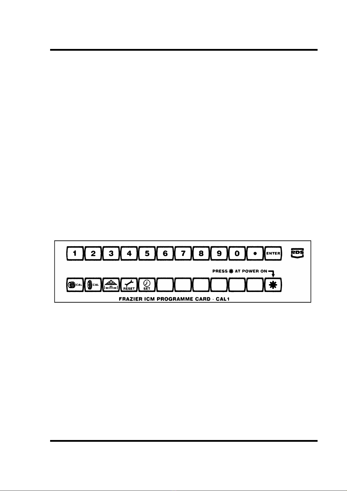
Afront panel overlay card is provided which indicates the new "programme mode" functions of each of
the buttons along the bottom of the instrument.
The ICM Overlay Card
Entry into programme mode
a/ Select either Metric or Imperial on the instrument according to which units you wish to use for
programming and then switch the ignition off.
b/ Position the overlay card on the front panel of the instrument over the function buttons.
c/ Press and hold down the *button whilst switching the ignition back on.
d/ The LH display will show "CAL" to confirmthat the ICM is in programme mode. The *button should be
released immediately that "CAL" is displayed.
e/ The functions of all the lower buttons have all now changed to those indicated by the overlay card.The
LH display will show the value of any of these factors currently set in the instrument simply by pressing
the appropriate function button.
f/ The upper row of buttons (immediately below the displays) have also changed to become data entry
keys having values of 1to 9, 0, decimal point and ENTER.
Operating -ICM
13

Data entry procedure
All numerical data is entered by the same procedure as detailed below:
a/ Select the programme function to be checked or altered by pressing the appropriate button on the
overlay card. The LH display will show the numerical value currently stored for that function.
b/ If the value is correctly set then no further action is required. Simply select the next function to check
or switch the ignition off to return to operating mode.
c/ To set anew value use the top row of buttons as numerical entry keys .Key in the number, as the first
key is pressed the number will flash in the LH display and the RH display will flash "Ent". As the full
number is keyed in, it will all appear in the LH display. Each key press is acknowledged with an audible
beep.
d/When the number is correctly set, press "Enter" to confirm the entry. The display will then stop flashing
and the new data value is displayed in the LH window.
If you enter your value incorrectly, simply press "Enter" at any time and then enter the value again.
Data values
Wheel calibration 1&2
The data value to be set on these functions is the distance the vehicle travels forwards over 2intervals
between speed sensor pulses.
This data must be determined under practical operating conditions to allow for any wheel slip, sinkageor
tyre deformation.
The Agribuggy is fitted with apropshaft speed sensor and the data programmed is the distance the
machine travels forwards for two revolutions of the prop shaft. Determine this distance by driving the
machine forwards for exactly 20 revolutions of the prop shaft, measure the distance travelled and divide
this distance by 10 to determine the true "speed sensor factor" or distance travelled between 2sensor
pulses.
The following settings are the factory settings and are only approximate. The machine should be
re-calibrated before use and the new settings recorded for future reference.
Tyre size Metric factor (metres) Imperial factor (inches)
38x20x16 low pressure 0.891 35.10
12.4 x16 intermediate 0.905 35.63
9.5 x24 intermediate 1.06 41.76
7.2 x36 row crop 1.207 47.53
8.3 x36 row crop 1.28 50.43
7.2 x40 row crop 1.347 53.04
An alternative method of calculating the wheel factor, although not as accurate, is as follows:
Measure the distance from the ground to centre of the axle whilst in working conditions and approximately
half loaded. Multiply this figure by 2.04 to get the wheel sensor factor.
Operating -ICM
14

Implement width
The data value to be set on this function is the full working width of the sprayer or spreader in either
metres or inches.
Time set
The data value to be set on this function is the time of day. Enter the hour followed by minutes e.g. 0915.
Service interval reset
To reset the service interval counter press and hold down the function button for aminimum of 5
seconds. The LH display will then show the hours remaining to the next service and the next service type.
Hydraulic PTO system.
For information on the optional high power PTO system (Airtec) please see appendices
Safety
1/ Ensure PTO is disengaged before starting engine.
2/ The engine MUST be switched off before connecting the PTO or making any adjustments.
Operation
The PTO is hydraulically driven, is fully independent and may therefore be engaged at any time providing
the engine revs are not too high. To engage the PTO press the PTO switch down on the dashboard. (see
below) Alamp built into the switch will illuminate continually whilst it is switched on.
Operation -Hydraulics
Windscreen wash
Windscreen wipers
Side/headlamp switch
Hazard warning lamps
PTO on/off
PTO speed control
Dashboard switch bank
15

Setting PTO speed
The hydraulic pump is geared so that 540 r.p.m. on the PTO is reached at aminimum engine speed of
2400 rpm To set the PTO for 540, or indeed any other required speed, increase the engine speed to
approx. 2800 rpm and adjust the speed with the knob immediately below the PTO switch. NB. the knob
must be pulled out before turning to unlock it and pushed back in afterwards. The actual PTO
speed can be read off the LH display of the ICM (see previous pages). Turning the knob clockwise will
increase the speed and anticlockwise will decrease the speed.
Once the speed is set, if the engine rpm is increased there will not be a significant increase in PTO
speed. The PTO speed should never exceed 600 rpm For most spraying operations you will find it is
not necessary to always run the PTO at 540 rpm. Lower PTO speeds result in reduced wear and tear
in the spray pump and hydraulic system, alower engine power requirement and can help to prevent
foaming in the spray tank.
If the sprayer is fitted with ahigh capacity spray pump e.g. 4, 5or 6cyl. the PTO speed should
be set as low as possible whilst spraying. Speeds in the order of 350 rpm for a 6 cyl. pump and 450
rpm for a 4 cyl. pump are normally more than adequate to achieve working pressure with excess flow left
for agitation. Higher speeds may result in overheating of the hydraulic system. The PTO speed can then
be increased to 540 after each load for quick-filling if required.
It is important to ensure that sprayer filters are kept clean and that self-cleaning filters are
working correctly at all times. Failure to do so will result in loss of PTO speed and overheating of
the hydraulic system.
Spool valves
The levers to operate the spool valves are situated to the left of the drivers seat. Labels on the inside of
the door and on the back of the battery box (next to hydraulic connectors) show which lever operates
which connector. There may be up to 4valves fitted which can be any combination of single and double
acting spools. Adouble acting spool can be safely used to operate asingle acting service if required.
The hydraulic system/spool valve(s) fitted are only designed for intermittent operation of hydraulic
cylinders and should not be used to power motors or other hydraulic circuits. Maximum pressure at the
spools is approx. 1800 psi (124bar) Please consult the manufacturer if you require higher pressures orif
wish to use them for any other purpose.
Please ensure that all couplings are clean before connecting hoses and that any couplings that
are not in use are protected with plugs /caps. Ingress of dirt into the hydraulic system can lead to
premature wear and possible failure of major components.
Air Conditioning /ventilation
The air conditioning unit (if fitted) is integrated into the ventilation system within the cab roof. The unit will
cool or heat the air which is partly drawn in to the cab through the carbon filter system and partly
re-circulated. This ensures the cab is kept positively pressurised to keep dust and vapours out of thecab.
Machines without air conditioning draw the whole air supply through the carbon filter.
Operation
To operate the fan, turn the centre switch in the roof panel clockwise until you find the most preferred of
the three speeds. The adjustable vents in the roof console can be directed to wherever you require the
air.
Operation -Ventilation
16
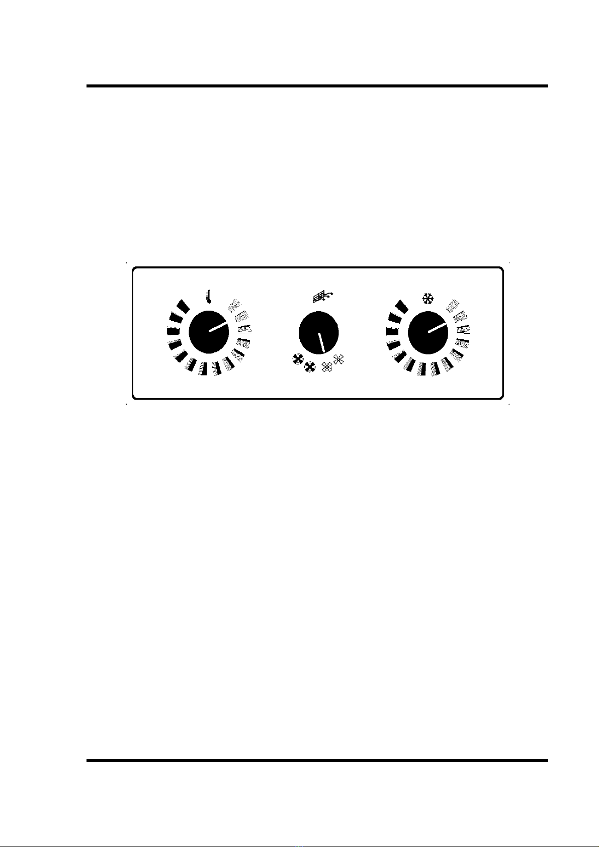
To reduce the temperature of the air, turn the RH switch clockwise until the cab temperature is reduced
as required. For maximum efficiency the LH control for the heater should be turned fully anti-clockwise.
Remember the chiller will only work when the engine is running at over 1200 rpm.
Always keep the cab door closed to keep the cab cool.
To increase the temperature of the air turn the LH heater control clockwise and the chiller control
anti-clockwise.
Demisting
In damp conditions the heater control can be used in conjunction with the chiller to dehumidify the air
entering the cab -to demist quickly turn both controls fully clockwise.
Row crop work.
Only row crop wheels recommended by the manufacturer should be fitted to the Agribuggy. Fitting any
other wheels will invalidate the warranty. Wheel track should not exceed 72’’ without consulting the
manufacturer. The top road speed is increased significantly when row-crops are fitted, however, atop
speed of 30 m.p.h. (50 kph) should still NOT be exceeded. Speeds over 20 mph (32 kph) should only
be used if the tyres fitted are suitable.
Please read notes on steering stop adjustment if you are fitting row crops on an Agribuggy with awheel
track of less than 68’’. The stops may have to be altered to maintain adequate wheel/cab clearances. It
as also advisable to service the brakes as amatter of course before fitting row crop wheels in the Spring.
It is recommended that the front crop deflector and underbelly crop sheet be fitted when working
in tall crops particularly as harvest approaches. This not only reduces crop damage but also
protects the underside of the machine and stops the crop being pulled into the drive belts, shafts
and alternator etc.
The front mounted crop deflector also helps to prevent the radiator from blocking. It may have to be
extended for use in oil seed rape and some other tall crops. If so please ensure that the extension does
not restrict the air flow into the radiator, especially when being used on the road.
See appendix 6for row crop wheel track settings.
Operation -Row crops
Heater control Fan speed Chiller control
Ventilation controls
17

Field Operation
The optimum working speed of the Agribuggy in reasonable conditions is 6-9 mph. (10-14 kph) This
speed is normally achieved in second gear for 7.5 mph (12 kph). If conditions are good, you may be
able to travel in third gear as long as the engine is not labouring.
Try to keep between 2200 and 3400 rpm. Slow down and select alower gear if necessary.
High engine revs will result in higher engine temperatures and fuel consumption.
The suspension of the Agribuggy gives it arelatively smooth ride compared with atractor, however, it
should still be driven with care and respect especially over rough ground.
Should you get badly "bogged down" when working in wet conditions, ensure that mud has not been
forced up into the crankshaft pulley /drive belt area. If it has, then thoroughly clean the area and check
that the camshaft drive belt cover has not been damaged and that mud has not got inside the cover.
Please seek advice immediately, from T.J. Frazier Ltd., if it has.
Field planning.
Try to plan your field before you start work. You will soon find out what the Agribuggy is capable of. If a
field has any particularly wet areas or steep banks, plan the field so that your load is reduced before you
reach them. If it has avery steep hill in it, it is advisable to reduce your working speed to 6mph to do the
whole field. 1st and 2nd gear can then be used. When spraying at relatively high speeds, it is very
important that your working speed is maintained to avoid over or under dosing. For this reason it is
important that two 12 metre bouts are sprayed around the headland before spraying the rest of the field.
When spraying the rest of the field maintain your speed as you travel onto the headland and do not start
to turn until the sprayer is switched off. After turning, straighten up, and try to get up to your target speed
before switching back on.
Potatoes.
When spraying potatoes with row crop wheels fitted it is most important that care is taken when turning. If
adummy headland is left between the field rows and the headland rows you may find it necessary to
shunt when turning to avoid crossing over the headland rows. Go as slow as possible (bottom gear) if
turning over the rows is unavoidable to ensure unnecessary strain on the machine is kept to aminimum.
Sugar Beet.
When spraying sugar beet you will find it best to look forwards and drive by the centre of the machine
rather than trying to look down at the wheels. Fit acentre marker on the bonnet if necessary. For
low-dose/high pressure spraying forward speed should not exceed 6mph (10 kph). We recommend the
use of ajet which will apply 7+-10 gals (75-110 l/ha) at 5mph (8 kph) at 45-50 psi (3.25-3.5 bar). E.G.
Lurmark 015-F110 (light brown).
Choice of jets.
We recommend the use of 110 degree fan nozzles for general high speed spraying. These will give
better coverage than 80 degree jets with amore appropriate droplet size. Twin outlet or twin jet capswill
give even better coverage. However, you should always check on your chemical container for
recommendations regarding forward speed, pressure, spray quality and water rates before choosing
which nozzles to use.
Field Operation
18

Forward speed
Most spraying operations can be carried out at 7.5 mph (12 kph), however the following points should be
taken into consideration: The spray boom should ride evenly and should not bounce and yaw about. An
unstable boom is one of the main causes of uneven application and is probably the main reason why
chemical manufacturers and suppliers often recommend aslower working speed. If the crop is
particularly dense or tall and good penetration is essential reduce your speed to 6mph (10 kph). Also
remember that, contrary to popular belief, increasing pressure does not increase penetration. It simply
increases the number of smaller droplets which will settle on the upper leaves or blow away. e.g. for
pre-harvest Round-Up amax speed of 6mph (10 kph) and a pressure of 30 psi (2 bar) is recommended.
If conditions are particularly rough, even if the boom is stable, it may pay to reduce speed for the sake of
the machine.
Fertiliser spreading.
Vicon spreaders.
When using Vicon spreaders the following points should be noted: When first fitted, the height of the
spout on the spreader is higher than that specified by the manufacturer. However, once loaded and in
the field you will find it will be a lot nearer the correct height above the crop. It is far better to be too high
than too low and this should have no significant effect on the spread pattern. As aguide, the last bit of
fertiliser should be hitting the previous wheeling. When spreading Nitram, or similar prilled material, the
rear mudguards should be removed to avoid any effect on the spread pattern.
The spreader has abuilt-in shock absorber in it’s spreading mechanism to avoid shock loads being
passed down the PTO shaft. It is very prone to seizing up. It should therefore be checked each time itis
used to avoid possible damage to the shaft and hydraulic motor. Check as follows: Wedge the flywheel
so it can’t move in either direction. Push ascrewdriver or bar through the PTO shaft yoke and try to turn
the shaft. It should move approx. 20 degrees against the force of the shock absorber and then spring
back to the central position. If it does not it should not be used till it has been repaired. If in doubt please
consult T.J. Frazier.
Lely Centreliner spreaders.
Ensure there is asheet fitted across the front of the spreader to avoid fertiliser being thrown forwards
onto the machine. This is most important and a better sheet than the one supplied with the spreader
should be fitted if necessary. Please remember the warranty does not cover faults caused by corrosion!
Due to the relatively low pressure that the Agribuggy hydraulics work at, the hydraulic control on the
spreader may be too slow. If it is, remove the restrictors in the end of the actuating rams. However take
care if it is also used onatractor -it may then work too fast and damage may result.
Apurpose made mounting frame is now available from T.J. Frazier which carries the later Centreliners
on a 3 point linkage. This allows the tilt angle to be altered with aspecial top link and allows use of the
headland tilt facility on the spreader.
Amazone spreaders.
Mounting frames are available for both Amazone ZAU and Amazone ZAM spreaders. Aguide is available
from T.J. Frazier for setting the spreaders up, however, as with all spreaders, it is advisable to have them
tray tested before use.
Field Operation
19

Seed Drilling
Safety
Only seed drill conversions supplied or recommended by T.J. Frazier Ltd. should be fitted to the
Agribuggy 5D. Incorrectly fitted drill units will invalidate the manufacturer's warranty, may be hazardous
to the operator and may seriously reduce the life of the machine or some of its major components.
The only drills currently suitable for fitting to the Agribuggy are those of the pneumatic type with
lightweight, Suffolk coulter toolbars up to amaximum width of 4metres.
Make sure you follow the safety, operating and maintenance instructions given by the respective drill
manufacturer.
Operation
When drilling with the Agribuggy, aPTO speed of 520 rpm is normally more than adequate to operate
this type of airseeder.
Whilst drilling the engine speed should not exceed 3200 rpm and ideally should be kept below 3000 rpm.
Wheel track eradicators should be set as shallow as possible to keep the draft load on the Agribuggy to a
minimum and following harrows should only be fitted to 3m units.
Maintenance
An oil-to-air hydraulic cooler unit must be fitted in front of the engine radiator when driving a pneumatic
airseeder. This should be kept perfectly clean together with the radiator immediately behind it. Failure to
do so will result in overheating of both the hydraulic and engine cooling systems.
Service &Warranty.
The Agribuggy carries a12month /500 hour warranty on defective parts and workmanship. It does not
cover faults caused by incorrect use and servicing or faults caused by fertiliser or chemical corrosion.
All servicing should be carried out as per this instruction manual during the warranty period. The first
service is normally carried out by the customer after the first fifty hours running. If any faults are
apparent on delivery, at this first service or during the warranty period we would be grateful if you would
notify us as soon as possible even if the fault is rectified by yourselves. We have found many people
repair straight-forward faults themselves without telling us, however our policy is one of continual
improvement and with your co-operation together with any suggestions and ideas we shall continue to
improve the machine to our mutual advantage.
If any problems occur with the machine please contact your supplier, without delay, with whom you can
discuss the best way to deal with the problem to avoid unnecessary delays. If arepair is carried out by
yourselves or by an outside engineer to save time, and you wish to claim costs under warranty, we must
be notified first or the claim will not be accepted under any circumstances.Unauthorised repairs
may affect or even invalidate any remaining warranty. Any parts replaced must be returned to us for
assessment.
If our service engineers are called out at any time ,to work on the machine or if the machine has
to be returned to our works for repair, it must be thoroughly cleaned to remove all chemical and
fertiliser residues to enable the work to be carried out safely and effectively. If the machine is not
clean ,we reserve the right to either refuse to carry out the work or to charge for cleaning.
Service &Warranty
20
Table of contents
Popular Farm Equipment manuals by other brands


Ziegler
Ziegler CORN CHAMPION K Series Operating and assembly instructions

GREAT PLAINS
GREAT PLAINS 1510HDP Operator's manual

Kverneland
Kverneland ES Operator's manual

Aitchison
Aitchison SEEDMATIC 40/4124 E Series manual

Land Pride
Land Pride Straw Crimper CR2572 Operator's manual

aivituvin
aivituvin AIR 04-B instruction manual