Red Dragon GF-2011 User manual

FLAME ENGINEERING, INC.
PO Box 577 • 230 West Hwy 4 • LaCrosse, KS 67548
800-255-2469 • 785-222-2873 • Fax 785-222-3619
www.FlameEngineering.com
GF-2011
Multi-purpose Flamer
Assembly and Operating Instructions
Please Read All Instructions and Save
These Instructions For Future Reference.
• This device is intended for outdoor use only.
• This unit is designed for a vapor-withdrawal
LP-Gas cylinder only.
DO NOT OPERATE THIS EQUIPMENT IF:
• You are subject to seizures, loss of
consciousness, or fainting.
• You have been drinking alcohol, using
illicit drugs, or prescription drugs that might
effect your judgment or balance.
• You have not read or do not
understand the operator’s manual.
• You are not capable of safely
operating this type of equipment.
DO NOT ALLOW CHILDREN TO
OPERATE THIS EQUIPMENT.
FOR YOUR SAFETY!
If You Smell Gas:
1. Shut off gas to the device.
2. Extinguish any open flame.
3. Check the device for leaks using soapy
water.
4. DO NOT attempt to relight the
device until leaks are repaired and there is
no gas smell.
DO NOT use this device in areas where
gasoline or other liquids having flammable
vapor are stored or used.
IMPORTANT WARNINGS:

To Assemble:
Note: Unpack and inspect for damage.
A. Slide handle into one of the receiver brackets in the configuration of your choosing. Secure with a 3/8 x 1/2 bolt (17).
B. Connect the 54” Rubber LPG Hose (4) to the 1/4 Female x 3/8 Male Flare Elbow (12). Do Not Over tighten.
C. Place LPG Cylinder onto the cylinder platform and secure with the nylon tank strap. See cover photo to see how the
strap threads through the heat shield.
Connecting To The Supply Cylinder:
The propane supply cylinder used with this torch should be no less than 20 lb. capacity and must be designed, fabricated,
tested and marked in accordance with regulations of the U.S. Department of Transportation, the Canadian Transport
Commission or the Interstate Commerce Commission. Supply cylinders must be arranged to provide for vapor withdrawal
from the operating cylinder.
1. Inspect the nut/nipple of the P.O.L. connection on the LP-Gas hose. Check for dents or physical damage. The O-ring
should be present on nipple fitting. If damage is evident, call for replacement parts.
2. Be certain the supply cylinder valve is fully turned off. Remove the protective plastic plug from the cylinder valve outlet connection.
3. Connect the P.O.L. nut/nipple fitting on the hose to the propane supply cylinder by turning the left hand threaded P.O.L.
nut counter clockwise into the cylinder valve outlet. Snug the connection tight with a wrench. DO NOT OVER TIGHTEN.
Lighting Instructions:
IMPORTANT NOTE
The P.O.L. contains an integral flow-check valve. Opening the LP-Gas cylinder valve rapidly can cause the valve to check.
If the P.O.L. flow valve checks, close the LP-Gas cylinder valve, wait 10-15 seconds and slowly open the LP-Gas cylinder valve.
• If no leaks are found, proceed with lighting the torch.
• Always use a flint lighter to ignite the torch. DO NOT USE MATCHES OR CIGARETTE LIGHTER TO IGNITE THE TORCH.
• Be certain the flame adjusting valve is closed before opening the LP-Gas cylinder valve.
1. Slowly open the LP-Gas cylinder valve. Check all gas connections to the torches for leaks with a leak detection
solution, such as soapy water. Leaks will be indicated by forming bubbles around the source. Please allow one minute for
bubbles to appear. Repair all leaks and retest for leaks prior to lighting torches.
2. Open the flame adjusting needle valve 1/8 turn or until a small amount of gas is heard escaping. Using a flint lighter,
ignite each torch. Do not place your hand or any part of your body in the path of the burners while lighting or operating
the unit. DO NOT USE MATCHES OR CIGARETTE LIGHTER TO IGNITE THE TORCHES.
3. Adjust regulator to the desired pressure. Lower pressure settings conserve fuel. Use the lowest setting that will allow
you an adequate rate of application.
4. Adjust the final size of the flames by using the flame adjusting needle valve.
FLAME ENGINEERING, INC.
PO Box 577 • 230 West Hwy 4 • LaCrosse, KS 67548
800-255-2469 • 785-222-2873 • Fax 785-222-3619
www.FlameEngineering.com

NOTE: Where shaft collars are used to secure
wheels or manifold, be sure set screws are installed
to line up with small drilled depression in shaft.
READ ALL INSTRUCTIONS & SAFETY PRECAUTIONS BEFORE OPERATING THIS MACHINE
FLAME ENGINEERING, INC.
PO Box 577 • 230 West Hwy 4 • LaCrosse, KS 67548
800-255-2469 • 785-222-2873 • Fax 785-222-3619
www.FlameEngineering.com
1 100-120-058 5/8” Lock Collar
2 V-3055* Flame Adjusting Needle Valve
3 HP2S 2’ LPG Hose
4 HP4.5S 54” LPG Hose
5 GFW-24 24” Diameter Wheel (5/8 Axle)
6 P-3200W* P.O.L.
7 567RC* 0-60 PSI Regulator
8 HP48HG 4’ Rubber LPG Hose
9 F-322* 1/4 Hex Coupling
10 F-422* 1/4 Female Elbow
11 G-25* Pressure Gauge
12 F-428* 1/4 Female x 3/8 Male Flare Elbow
13 VT2 ½-0 Vapor Torch
14 1/4 X 3/4 Bolt
15 5/16 Lock Washer
16 5/16 Nut
17 3/8 X 1/2 Bolt
18 100-303-062 Tank Strap
19 100-117-005 1/4 X 2-1/2" Black Pipe Nipple
20 F-422ST45* 1/4 45 Degree Street Elbow
10
16
15
2
12
87
6
4
13
5
1
17
17
12
B
A
C
14
17
D
D
17
9
3
11
19 20
Connects
To Propane
Cylinder

Operating Notes:
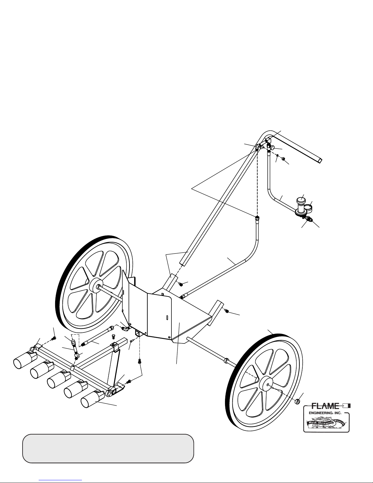
1. The torch manifold angle may be adjusted by loosening
the lock collars (D) holding the manifold bar. The
manifold may also be adjusted in or out from the unit
by loosening the 3/8 x 1/2 bolt and sliding the tee
bracket.
2. The wheel width may also be adjusted by loosening
and moving the lock collars on the axle. The handle
may also be assembled in a number of positions
depending on which bracket you slide it into and which
direction you point the “L” of the handle.
To Shut Down:
1. Close the LP-Gas cylinder valve.
2. Allow the gas to burn out of hose. After the flame is no
longer visible, turn the flame adjusting valve to the
closed or “off” position. TO RESTART follow lighting
instructions.
Disconnecting From Supply Cylinder:
1. Be certain supply cylinder valve is turned off.
2. Disconnect the P.O.L. nut/nipple fitting on the LP hose
to the propane supply.
3. Replace the protective plastic plug into the cylinder
valve outlet.
Safety Check List:
• Gloves should be used at all times. Long sleeves, long
pants & boots are recommended.
• Use only with cylinders equipped with vapor withdrawal
valves.
• Secure cylinders in a level, upright position. Do not invert or
lay cylinders on their sides.
• Do not apply flame to cylinders to check for leaks or to
increase gas pressure.
• Keep torches, open flame and sources of ignition away from
cylinders, regulators and hose.
• Do not operate torches or any equipment if the odor of
LP-Gas is evident. Immediately shut off all valves and, using
soapy water, check all equipment for leaks.
• Cylinder valves must be protected. Do not hoist a cylinder by
the valve.
• Do not leave the unit unattended while in operation.
• This equipment is for outdoor use only with adequate
ventilation.
• Have a type ABC fire extinguisher on the job site, easily
accessible to the person operating the unit.
WARNING:
Use extreme caution at all times. You are using an intense
open flame. This torch produces an extremely hot and
nearly invisible flame. Read and follow the Safety Check
List and Daily Equipment Check List before attempting to
operate this torch.
CAUTION
• Propane is heavier than air which can cause it to
accumulate in low areas. Be certain all areas are well
ventilated.
• Propane has a distinct ODOR. If you smell it,
IMMEDIATELY discontinue work, extinguish all flames,
locate the leak and correct it, ventilate area
before lighting torch.
• Use extreme caution at all times. This device has an
intense open flame. Disregard of safe practices can result
in severe fire damage, personal injury, or possible death.
• Never direct torch flame toward any person or animal.
FLAME ENGINEERING, INC.
PO Box 577 • 230 West Hwy 4 • LaCrosse, KS 67548
800-255-2469 • 785-222-2873 • Fax 785-222-3619
www.FlameEngineering.com GF-2011-INSTUCT8-2013
Popular Farm Equipment manuals by other brands

McElroy
McElroy PolyHorse Operator's manual

greenhouse sensation
greenhouse sensation Hydropod Assembly and maintenance instructions

Horst
Horst Contour SHCF36 Operator's manual

Jay-Lor
Jay-Lor 2300 Operator's manual

AGCO
AGCO Glencoe DR8500 Series Operator's manual

Raven
Raven Sidekick Pro Quick Installation Reference