T-MAX POWER BOARD PST05-0110 User manual
Tundra
POWER BOARD
Tundra
POWER
BOARD
Tundra
POWER BOARD
INSTALLATION
GUIDE
PRODUCT NUMBER: PST05-0110/PST05-0130
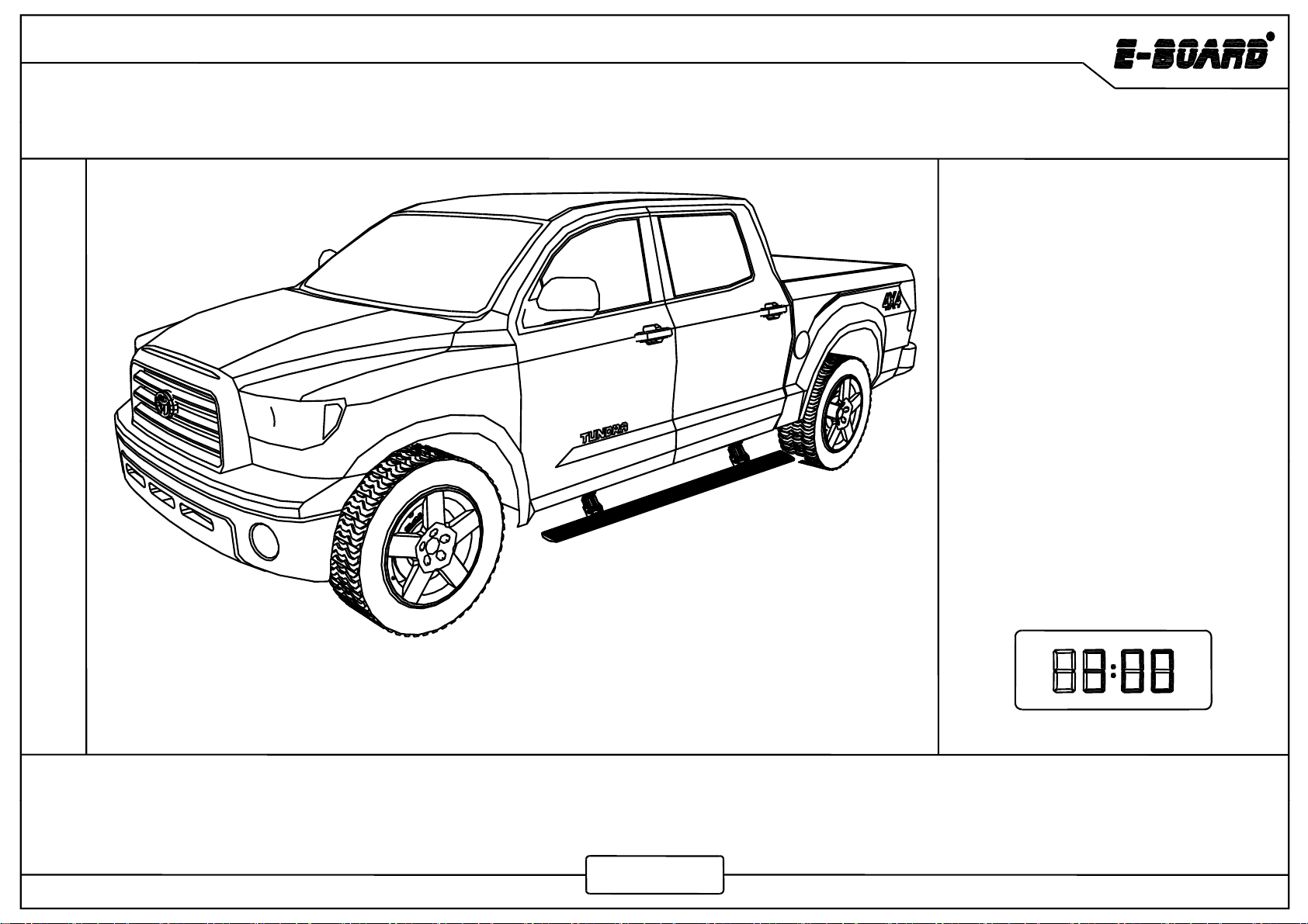
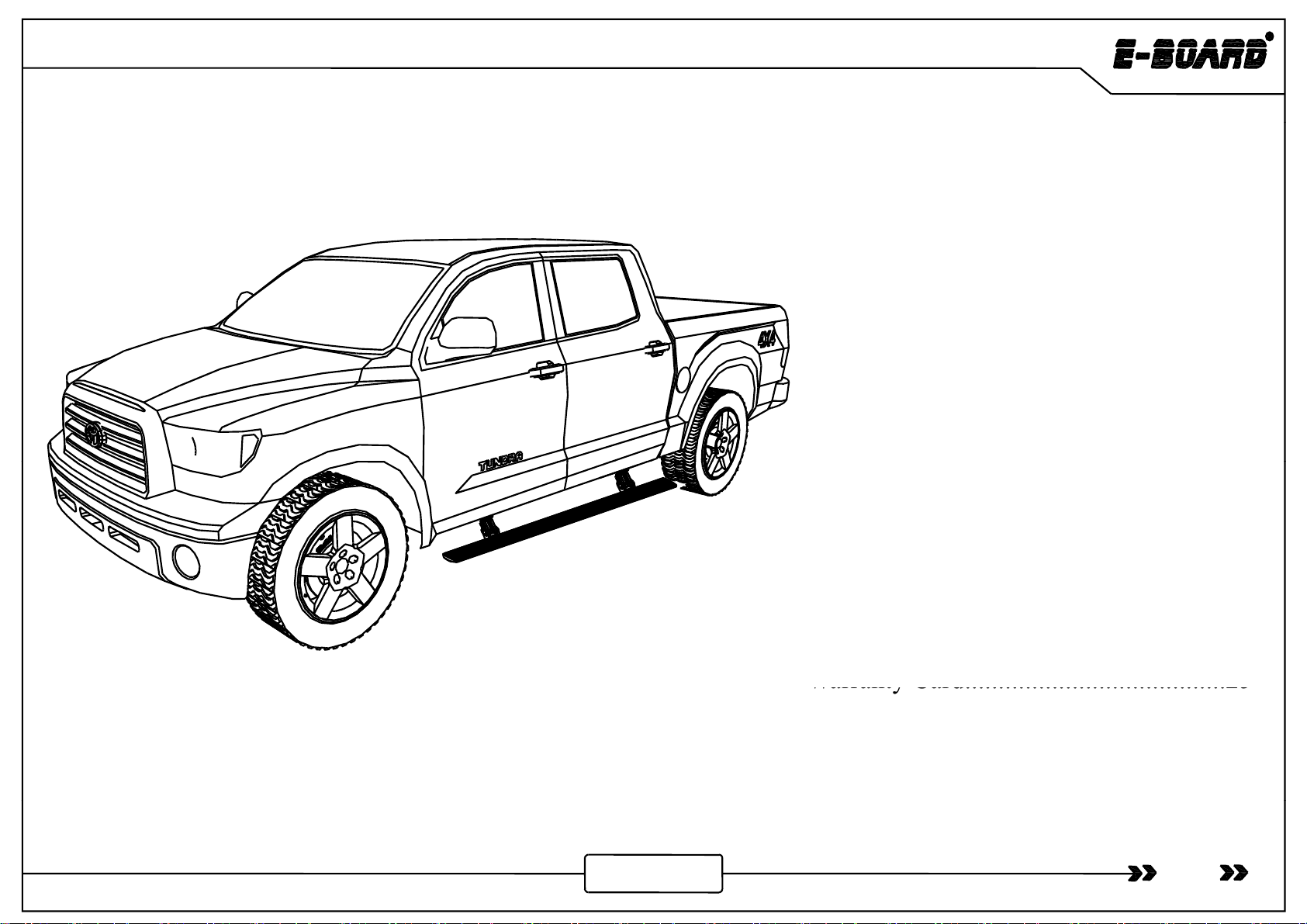
APPLICATION: Tundra Crew Max 2007-2018
Tundra Double Cab 2007-2018
TOOLS REQUIED:①5mm Hex Key Wrench(Allen wrench)
②
PST05-2010/PST05-2030
②
13mm Socket Spanne
r
③Pry Tool ④Wire Stripper/Cutter
⑤Vinyl Tape ⑥Screw Driver
www.tmax.biz
Tundra
Contents
Product Technical Specification.............02
Product Packing List..............................03
Mechanical Installation.........................06
Electrical Installation............................13
Maintenance..........................................23
Warranty Card.......................................
25
Warranty
Card.......................................
25
The product is developed and produced by T-MAX, and the related patents are blow.
01
www.tmax.biz
Patents:US8,469,380;US9,656,609;US9,308,870;US9,688,205;US9,669,766

Tundra
Product Technical Specification
Rated Voltage: 12V
Specified Load: ≤350kg
Gross Weight: 23kg
FdEtiLth
157
F
orwar
d
E
x
t
ens
i
on
L
eng
th
:
157
m
m
(Horizontal distance between the edge of power
board and the vehicle door when the board extends)
Board falling dimension : 267mm
(Vertical height difference between the edge of
power board and the vehicle door while board
extending).
(Both dimensions of forward and falling are
theoretical, which may vary due to uncertainties
such as installation errors, manufacturing errors of
vehicle bottom and etc.,)
Note:Impact load is not allowed.
Pl
k h hild d h d ill k 20 f di hil b d i ki id
b
j
02
Pl
ease ma
k
e sure t
h
e c
hild
ren an
d
t
h
e age
d
w
ill
k
eep
20
cm sa
f
e
di
stance w
hil
e power
b
oar
d
i
s wor
ki
ng to avo
id
any
b
ump or
j
am.
www.tmax.biz
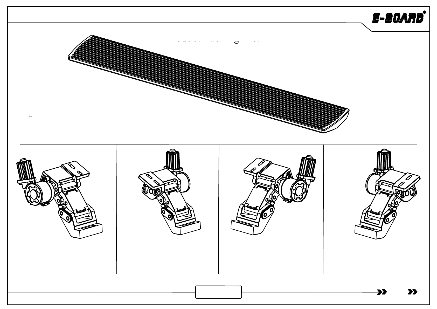
Product Packing List
Tundra
Product
Packing
List
①
①
- Board Assembly ×2
Crew Max
Crew Max
Crew
Max
Crew
Max
②- Front Motor Linkage Left ×1
6144100.1L
③- Rear Motor Linkage Left ×1
6144100.2L
④- Front Motor Linkage Right ×1
6144100.1R
⑤- Rear Motor Linkage Right ×1
6144100.2R
03
Crew Max Crew Max
www.tmax.biz

Tundra
Double Cab
Double Cab
Double
Cab
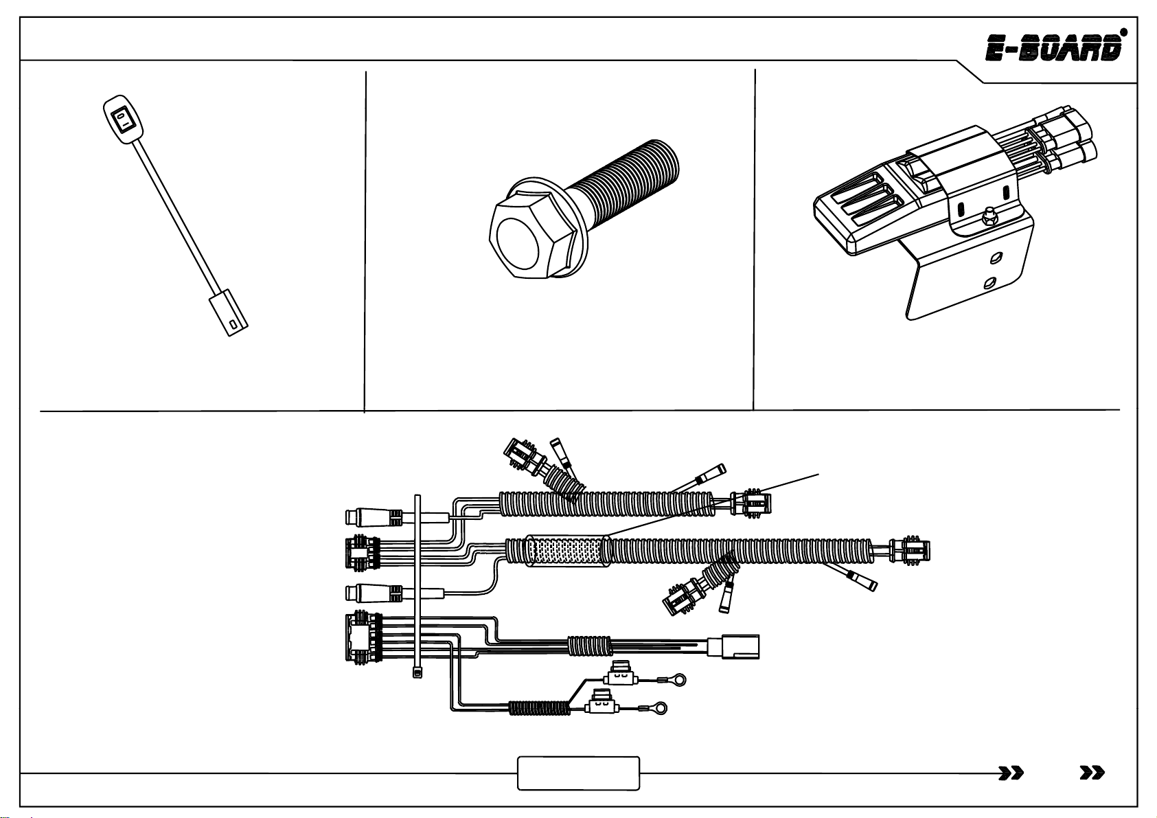
⑧- Hexagon Flange Bolt×8
QC/T340-1999 M8×30
⑨- Socket Cap Screw ×8
GB/T70.1-2000 M6×25
⑥- Rear Motor Linkage Right ×1
Double Cab
⑦- Rear Motor Linkage Left ×1
Double Cab
Magnet
⑩-WireTie×25
GB/T22344-2008 5×300
⑪-LED Lamp ×4
6161100.4.8
⑫- Fuse×2⑬- Wired Magnetic Induction
Module ×2
Magnet
04
(Optional)
www.tmax.biz
- Magnet ×4
Tundra
⑮- Hexagon Flange Bolt×2
QC/T340-1999 M8×25
⑭- Power Board Switch ×1
6124151.4.9
⑯- Controller Assembly
6144100.4.4ZJ
l(d)
Protection tube for high
temperature and burning
Four-core waterproof plug
Two-core plug (black)
Two-core p
l
ug
(
re
d)
Six-core waterproof plug
(
Positive
Red
)
(Negative-Black)
05
www.tmax.biz
⑰- Control Input Wire ×1 6144100.4.1
(
Positive
-
Red
)
MhilItllti
Tundra
M
ec
h
an
i
ca
l
I
ns
t
a
ll
a
ti
on
I t ll ti
iti
Ah ith it
th th
t
I
ns
t
a
ll
a
ti
on
p
os
iti
on
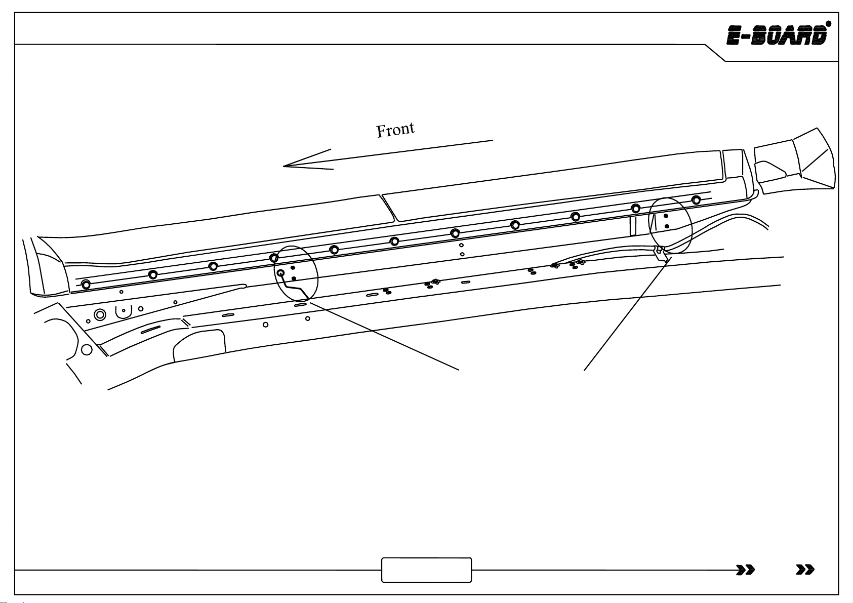
Installation Position On the Left Side
A
s s
h
own
i
n
th
e p
i
c
t
ure,
th
ese are
th
e
t
wo
installation positions on the left side of the
vehicle, and the installation mode of the front and
rear linkage are similar .
06
www.tmax.biz
Tundra
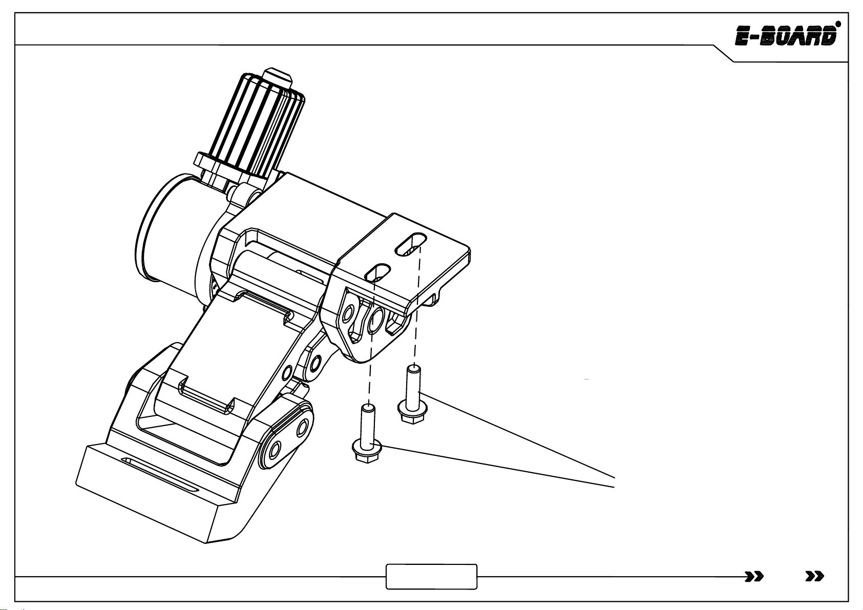
Motor Linkage Installation
Note
Crew Max
Note
:
Crew
Max
From step 1 to step 3;
Double Cab
Ste
p
4.
p
Hexagon Flange Bolt M8×30
07
www.tmax.biz

Tundra
Crew Max
Step 1:Turn the
brake wire bracket,
then se
p
arate the
Crew Max
p
bracket from brake
wire,remove the
bracket,and rotate
180°(Located at
the back of the
vehicle). Step 2 :Use screw to fix the brake wire
bracket underneath the brake wire.
Crew Max
Step3:Take the left side of Crew Max installation as
l
th b lt i th h l t t t
08
www.tmax.biz
an examp
l
e, screw
th
e
b
o
lt
i
n
th
e
h
o
l
e
t
o connec
t
mo
t
or
linkage with vehicle ,then tighten it(Tighten torque is
35 Nm).
Tundra
Double Cab
Double
Cab
Step4
:
Take the left side of
Double Cab installation
as an example
Step4
:
Take
the
left
side
of
Double
Cab
installation
as
an
example
,
screw the bolt in the hole to connect motor linkage with vehicle ,then
tighten it(Tighten torque is 35 Nm).
09
www.tmax.biz
Tundra
Crew Max
Crew Max:Symmetry of the front and rear
motor linkage.
Double Cab
Double Cab:The same of front and rear
motor linkage
10
motor
linkage
www.tmax.biz
Tundra
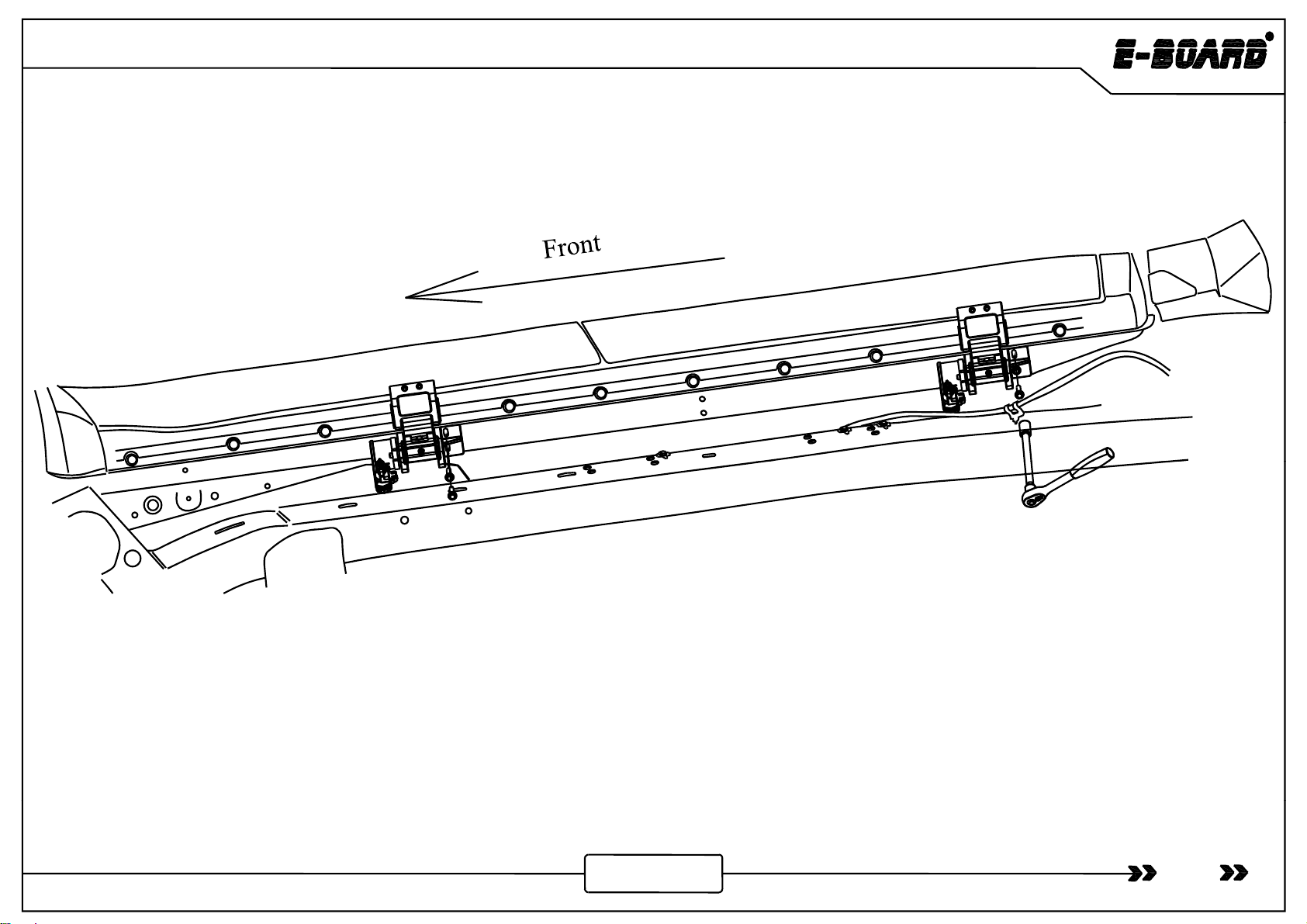
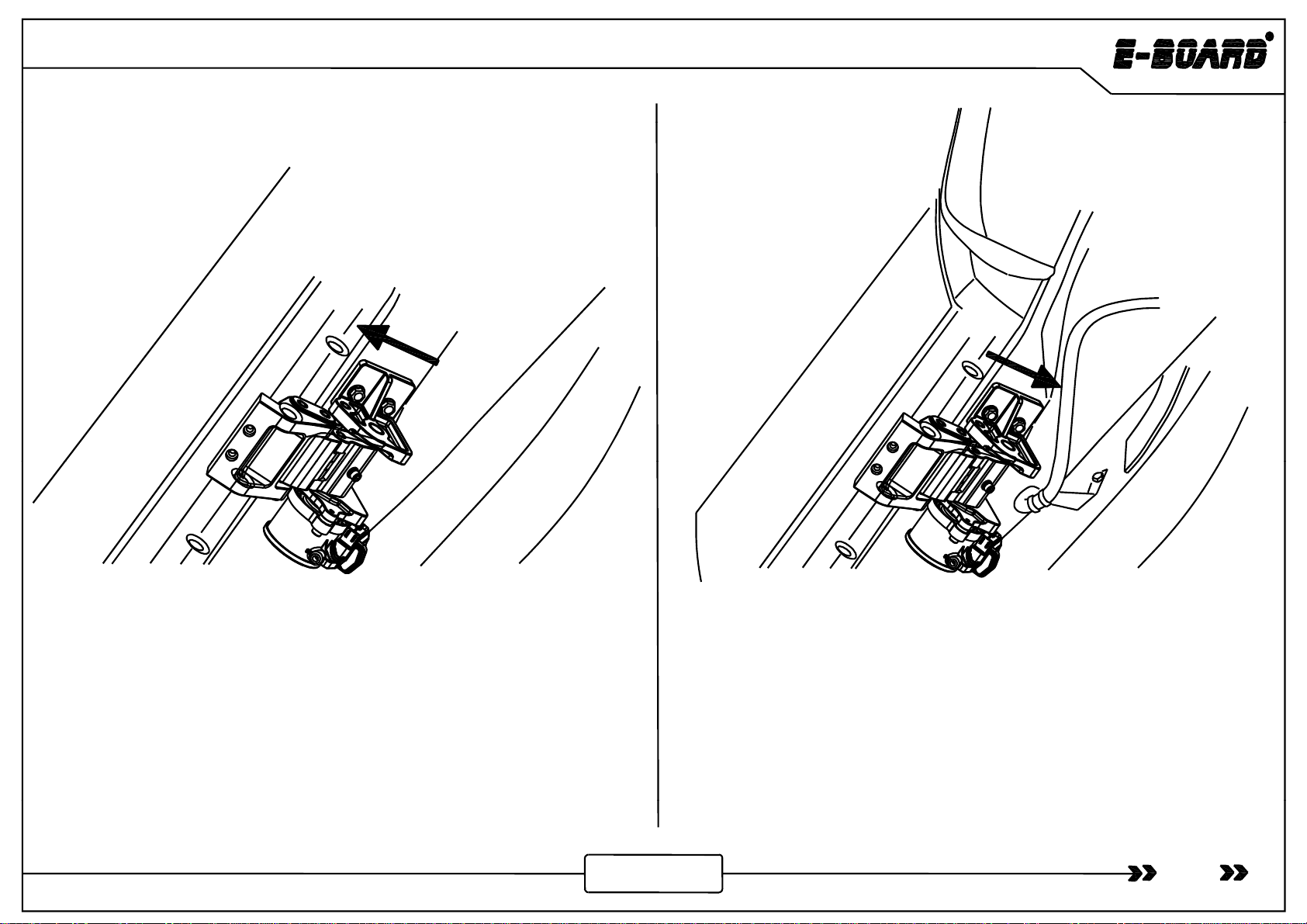
The installation of the right side for motor linkage and
The
installation
of
the
right
side
for
motor
linkage
and
board is referenced to the left side.
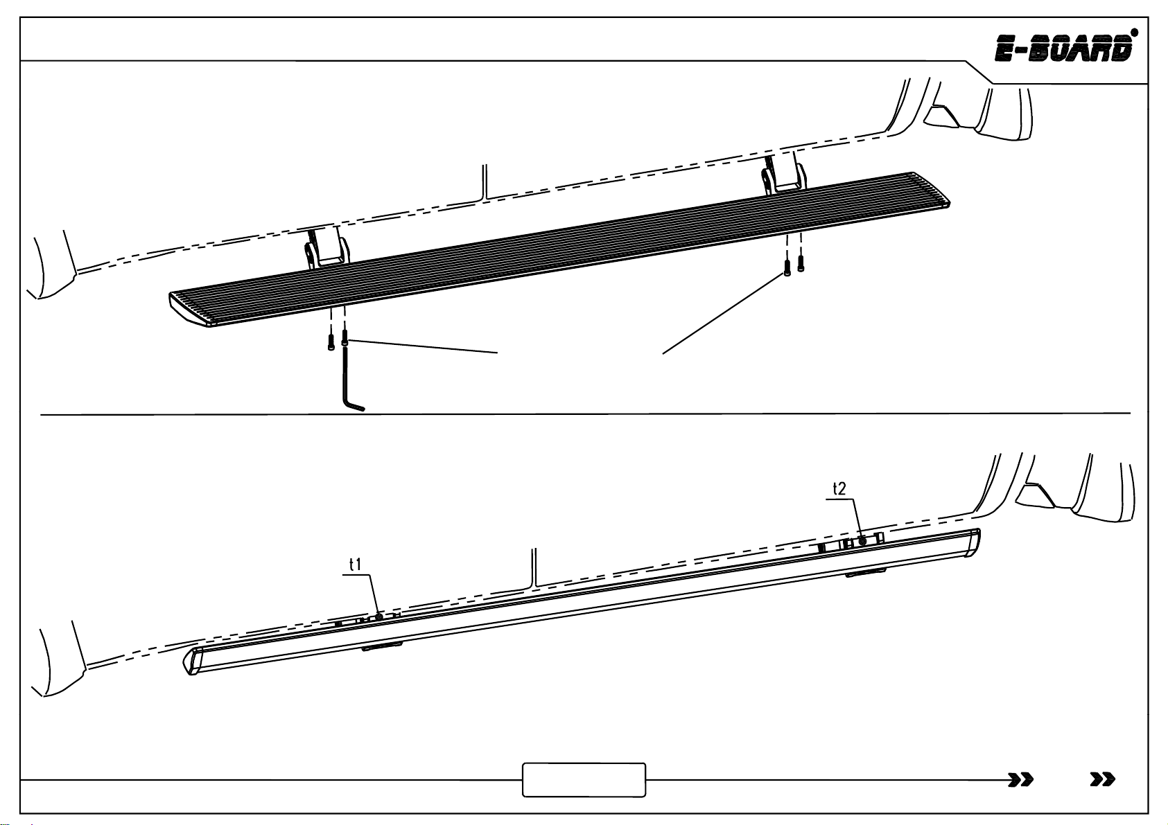
Step 5: Install the board and adjust
the T- nut to make the two end faces
of the
board
reach
to an
appropriate
Socket Cap Screw M6×25
of
the
board
reach
to
an
appropriate
position. Then use M6×25 socket
cap screws for connecting and
tightening (Tighten torque is12Nm).
11
N
ote:If the gap between board and vehicle t2 is larger than t1,the motor linkage should be adjusted.
www.tmax.biz
Tundra
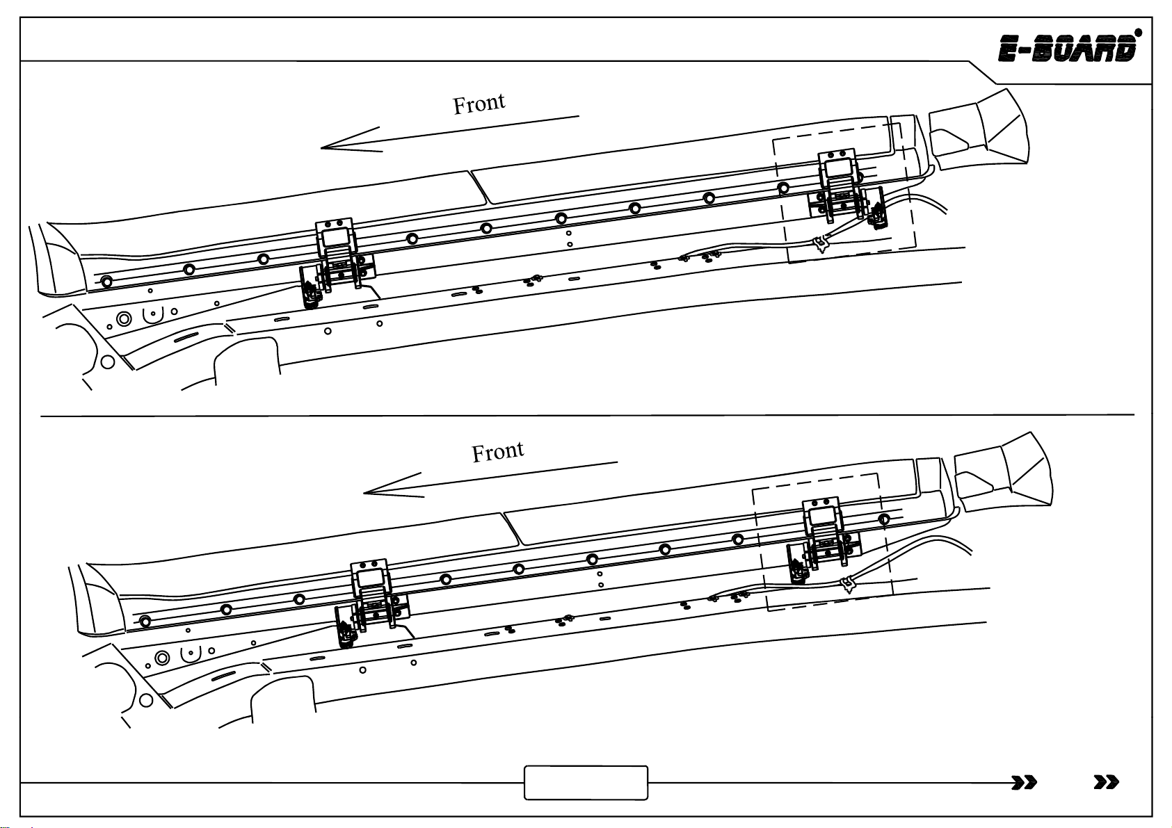
t1 t2
First
,
loosen two bolts here. Move the t1 First
,
loosen two bolts here. Move the t2
,
motor linkage to extreme position in the
direction of the arrow in the picture, and
retighten the bolts .
,
motor linkage to extreme position in the
direction of the arrow in the picture, and
retighten the bolts .
12
www.tmax.biz

The signal wire and power board switch
pass into the vehicle through the hole
Controller
Tundra
pass
into
the
vehicle
through
the
hole
.Electric
Installation by
Magnetic Control
1. Pull out the fuse and connect
th b tt
i
4.Connect white and brown signal wire with wired magnetic
induction module .
5. Insert back the fuse and sort
tth
i
th
e
b
a
tt
ery w
i
re.
Battery
Power board
switch
ou
t
th
e w
i
res.
3. Connect motor wire and LED lamp wire.
2. Connect the control wire and arrange all function wires to the pointed positions.
Chassis on the right
(The instruction is mentioned for the LED type. The installation for the basic type is basically similar to LED type,but the only difference is without LED lamp.)
Step 1: Find out the control input wire and pull out the fuse (ensuring
i it ft d i i tllti ) d
t th iti d
c
i
rcu
it
sa
f
e
t
y
d
ur
i
ng
i
ns
t
a
ll
a
ti
on
)
an
d
connec
t
th
e pos
iti
ve an
d
negative pole of wire harness to vehicle battery respectively.
Note: Battery wire can not be modified privately.
13
www.tmax.biz

Front
Btt
Tundra
Front
Left
Rear
B
a
tt
ery
Front
Front
Left
Lef
t
Controller
Front
Right
Left
Front
Right Rear
Right
Rear
Right
Rear
Left
Figure 1
Fi
gu
r
e
2
(upward view)
Left side
gu e
Figure 1 is the wire harness diagram and figure 2 is the installation diagram.
When install the wire harness, make sure the four connectors are connected with the four motor linkages by
“f t i ht i ht f t l ft d l ft”
14
www.tmax.biz
“f
ron
t
r
i
g
ht
, rear r
i
g
ht
,
f
ron
t
l
e
ft
an
d
rear
l
e
ft”
.
Tundra
M8 ×25 Hexagon Flange Bolt
Controller Assembly
Put the controller
assembly into the bolt
and then screw the
h
exagon
flange bolt
h
exagon
flange
bolt
and tighten it (Tighten
torque is 35Nm).
15
www.tmax.biz

Tundra
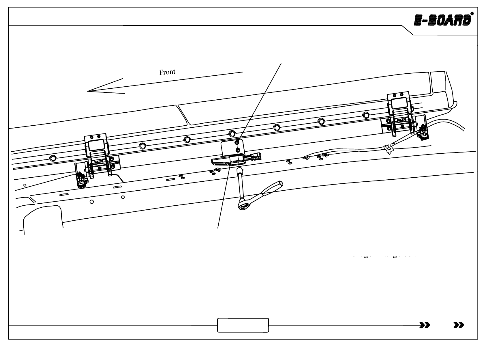
Front
Front
Chassis on the left
Step 4:The arrangement of motor wire and LED lamp wire: Arrange the motor connection wire along the beam as
shown in the picture, the motor wire plug extends to motors of linkage. At least , adjust the wire harness to make sure
shown
in
the
picture,
the
motor
wire
plug
extends
to
motors
of
linkage.
At
least
,
adjust
the
wire
harness
to
make
sure
it is tidy and beautiful.
The other side uses the same way for installation.
16
www.tmax.biz

Tundra
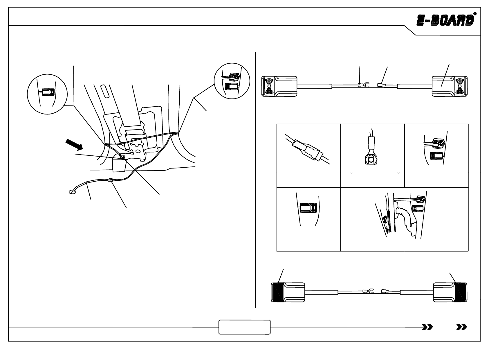
A -pillar panel
White signal wire
Brown si
g
nal wire
power board switch wire
Sill l
g
Sill
pane
l
Power board
switch
Figure 2
Figure 1
Figure 3
Step5: Connection of signal wire: Pry the sill panel and A-pillar panel in figure 1. Pull the white signal
wire , brown signal wire and power board switch wire into the vehicle through the rubber grommet on
the left side of the vehicle in figure 2. Then the white signal wire extends to the right side of the vehicle
17
www.tmax.biz
under the carpet, and stick the power board switch to the left side under the steering wheel in figure 3.
Magnetic Inductor Installation
Tundra
BAC
Induction part C
Induction part C
Wire Harness Magnetic Inductor
B
B-Pillar on the
right side (open
the cover plate )
Itthd ili
Ti
g
hten the nut connectin
g
Remove the adhesive tape at
the back of C and stick one
A
White signal wire
on the right side
Earthing stud D
(Negative)
I
nser
t
th
e
d
oor s
i
gna
l
w
i
re
into A
gg
B and ground terminal of
door pillars
the
back
of
C
,
and
stick
one
end on one side of the door
pillars
on
the
right
side
Step 6:Open the cover plate of B-pillar on the right side of the
vehicle , expose the above part (as shown above), connect the
white signal wire to terminal A of magnetic inductor, loosen the
earthing
st d
D connect fork t pe terminal
Btothe
earthing
Stick the other end to
the other side of
vehicle door pillars.
Stick the magnets to the inner side of the vehicle
door and keep their positions corresponding to C.
earthing
st
u
d
D
,
connect
fork
t
y
pe
terminal
B
to
the
earthing
stud , and then tighten the earthing stud. Stick the induction part
C to the both side of B-pillar, stick the magnet on the inside of
vehicle door which is corresponding with induction part. The
connection of
brown
signal
wire
and
wire
harness induction on
Magne
t
Magnet
18
connection
of
brown
signal
wire
and
wire
harness
induction
on
the left side are same with the installation of the right side. Instruction: The magnet position after closing the door is shown as above picture.
www.tmax.biz

Tundra
Step 7:Sort out the wire harness and close the panels.
19
www.tmax.biz
This manual suits for next models
3
Table of contents
Other T-MAX Automobile Accessories manuals

Popular Automobile Accessories manuals by other brands


Whelen Engineering Company
Whelen Engineering Company SA315EKT installation guide

Classic Accessories
Classic Accessories PolyX 300 instructions

Aries
Aries 2074106 installation manual

FILTRON
FILTRON K 1052A installation instructions

Cruz
Cruz N+ Series Assembly instructions

DICE
DICE Silverline DUO Installation guide & user manual