INSTRUCTION MANUAL
MONITOR
- LCD: 9”
- Resolution: 800 x 480 RGB (60Hz)
- Touch Screen: Resistive Touch
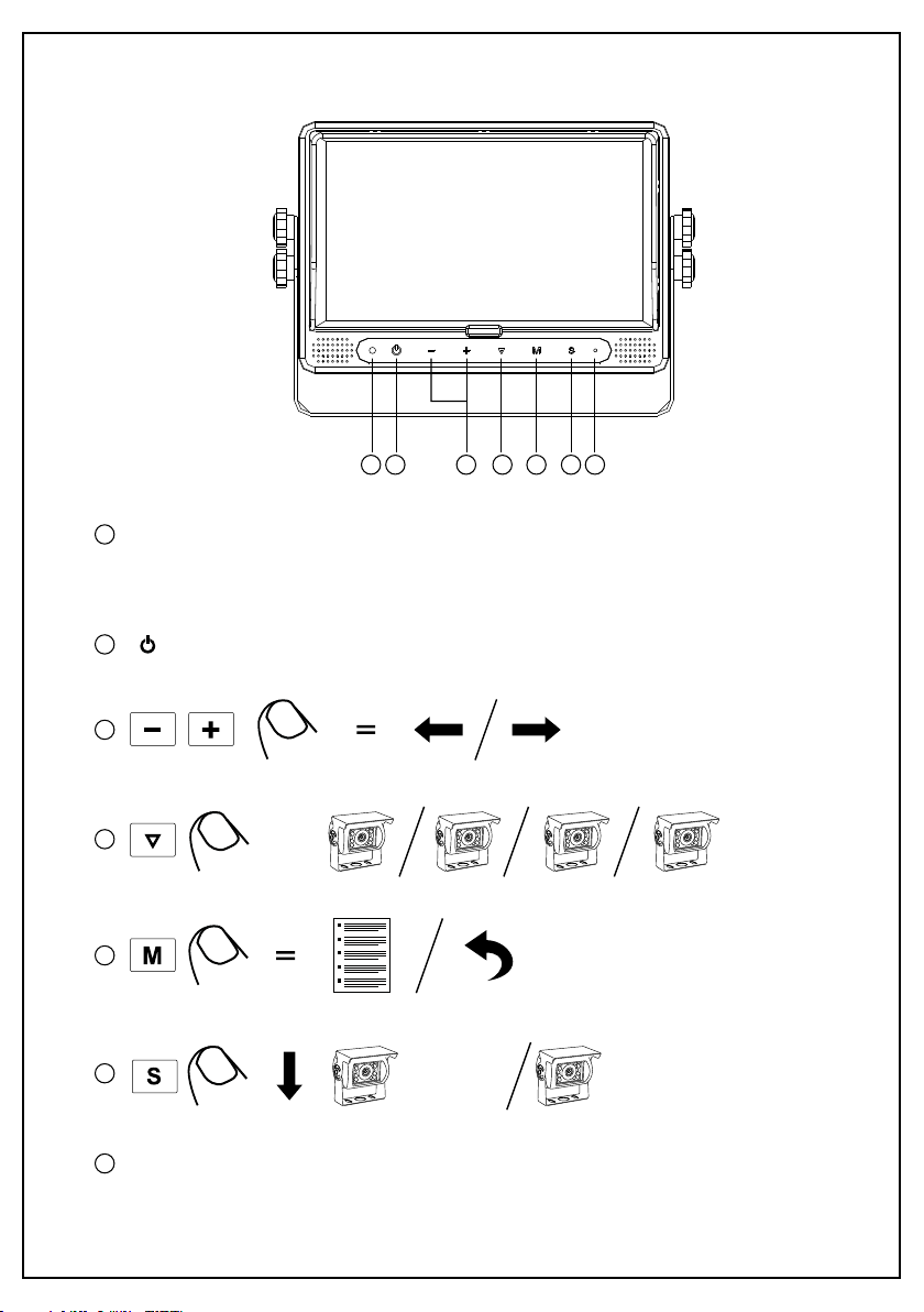
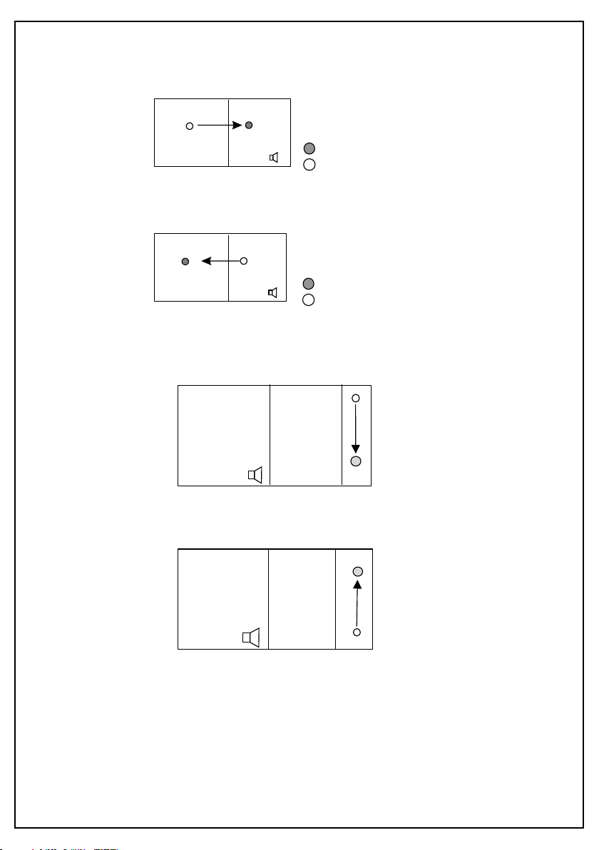
Can recognize up, down, left, right side “swipe”
Two-Point touch for channel switching
- Touch Buttons: Yes
- Backlighting Adjustment: 4 Manual Levels, 1 Auto Level
- System Format: PAL/NTSC
- Onboard Loudspeaker: Yes
- Mirror Orientation: Horizontal, Vertical, Horizontal-Vertical, Off
- Camera Image Display Mode: Single (Left/Right/Front/Back), Dual, Triple, Quad,
Picture In Picture (1/2/3), Trefoil, H-Split, Y-Split
- Camera Image Adjustment: Brightness, Contrast, Colour, Tint
- Menu Languages: English, Francais, Nederlands, Espanol, Deutsch, Italiano
- Trigger Lines: 5
- Trigger Priority: Yes
- Auto Scan: Yes
- Reverse Warning Gauge: Yes
- Automatic Start-up: Yes when triggered under standby
- Automatic Switch to Trigger CH: Yes
- Input: 4 x 4-PIN, 1 x AUX Audio
- Output: 2 x RCA Video, 1 x RCA Audio
- Operating Voltage Range: 10-32V
- Short-Circuit Protection: Yes
- Dimensions: 232W x 157H x 40D mm
2YEAR WARRANTY
JS1409Q
9” TOUCHSCREEN QUAD VIEW MONITOR
SPECIFICATIONS
INCLUDED
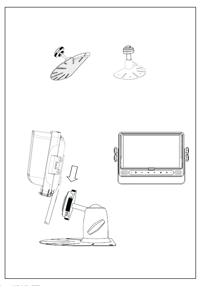
- Robust Bracket
- Stand Mount
- Sun Cover
- IR Remote