T-MAX E-BOARD PST01-0110 User manual

JEEP WRANGLER POWER BOARD
JEEP
WRANGLER
POWER
BOARD
JEEP WRANGLER
POWER BOARD
INSTALLATION
GUIDE
INSTALLATION TIME
Product Number :PST01-0110/PST01-0130
APPLICATION :2012-UP
Tools Re
q
uired :
①5mm Hex Key Wrench (Allen Wrench)
②13mm Socket S
p
anne
r
www.tmax.biz
PST01-0210/PST01-0230
q
p
③18mm Socket Spanner ④Vinyl Tape
⑤Cable Stripper/Cutter ⑥Scissors
⑦Electric Hand Drill ⑧φ10 Drilling Bit

JEEP WRANGLER
Contents
Product Technical Specification................02
Product Packing List.................................03
Mechanical Installation.............................08
Electrical Installation................................29
Maintenance..............................................30
Warranty Card...........................................32
The product is developed and produced by T
-
MAX and the related patents are blow
01
The
product
is
developed
and
produced
by
T
-
MAX
,
and
the
related
patents
are
blow
.
Patents:US8,469,380;US9,656,609;US9,308,870;US9,688,205;US9,669,766
www.tmax.biz
JEEP WRANGLER
Rated Volta
g
e: 12V
Product Technical Specification
g
Specified Load: ≤300kg
Board Length:
2D Length including end caps: 1.33m, 2D Length
without end caps: 1m
without
end
caps:
1m
4D Length including end caps: 1.86m, 4D Length
without end caps: 1.53m
Gross Weight: 20.5kg(2D)/ 27kg(4D)
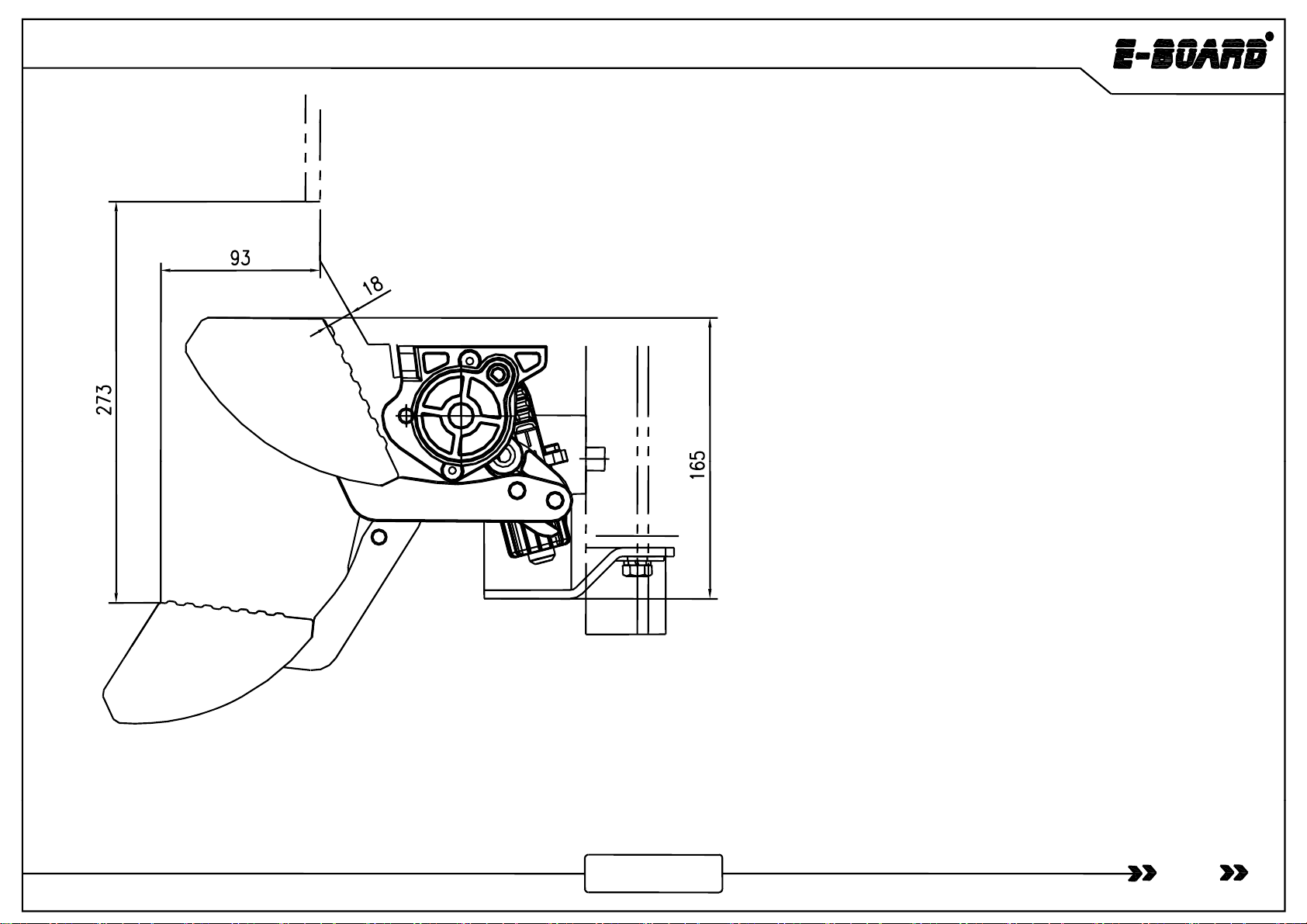
Fdtii93
F
orwar
d
ex
t
ens
i
on s
i
ze:
93
m
m
(Horizontal distance between the edge of power board
and the vehicle door when the board extends)
Board falling dimension: 273mm
(Vertical height difference between the edge of power
board and the vehicle door while board extending.)
(Both dimensions of forward and falling are theoretical,
which ma
y
var
y
due to uncertainties such as installation
yy
error, manufacturing errors of vehicle bottom and etc.)
Note:Impact load is not allowed.
02
Please make sure the children and the aged will keep 20cm safe distance while power board is working to avoid any
b
ump or jam.
www.tmax.biz
JEEP WRANGLER
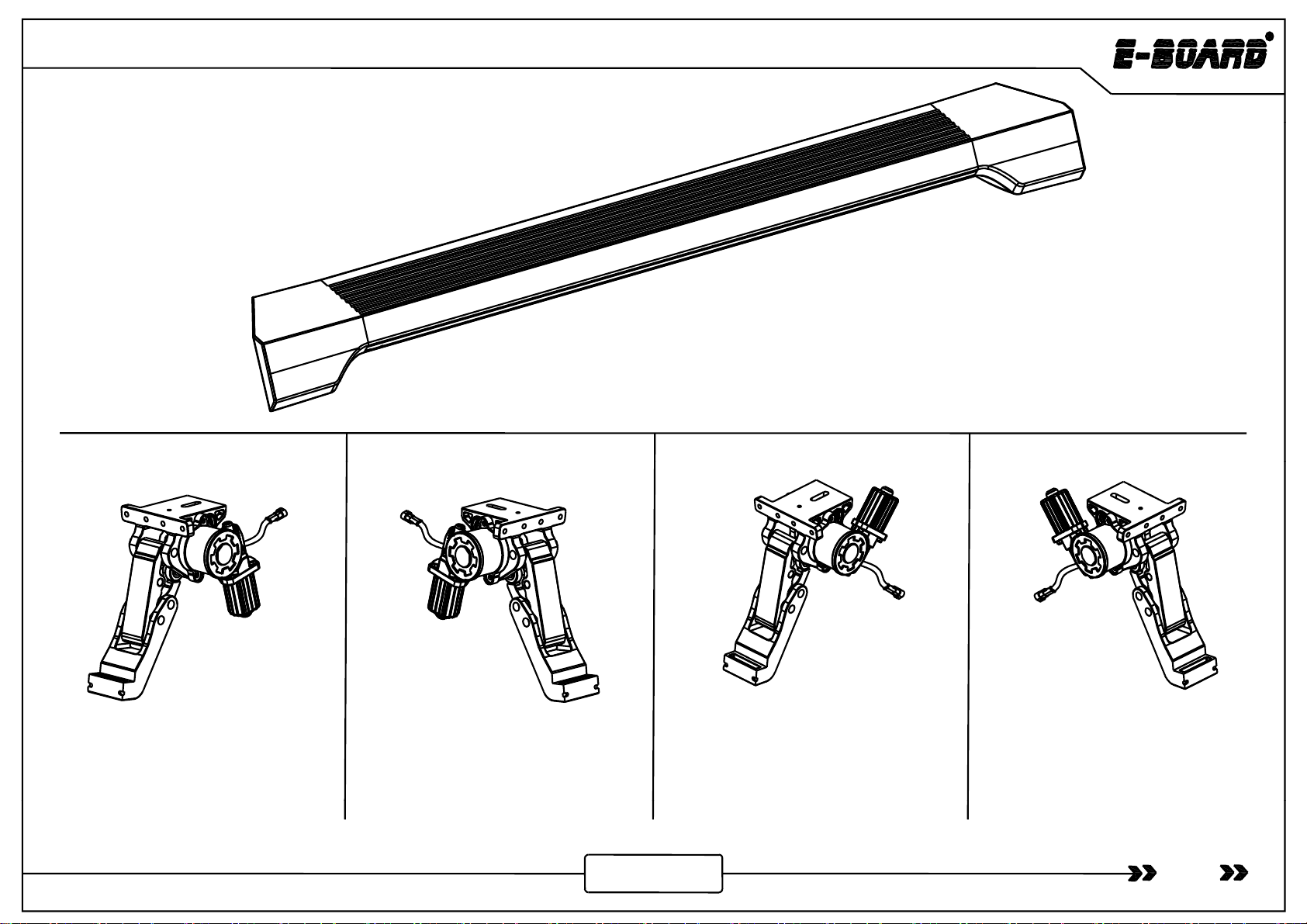
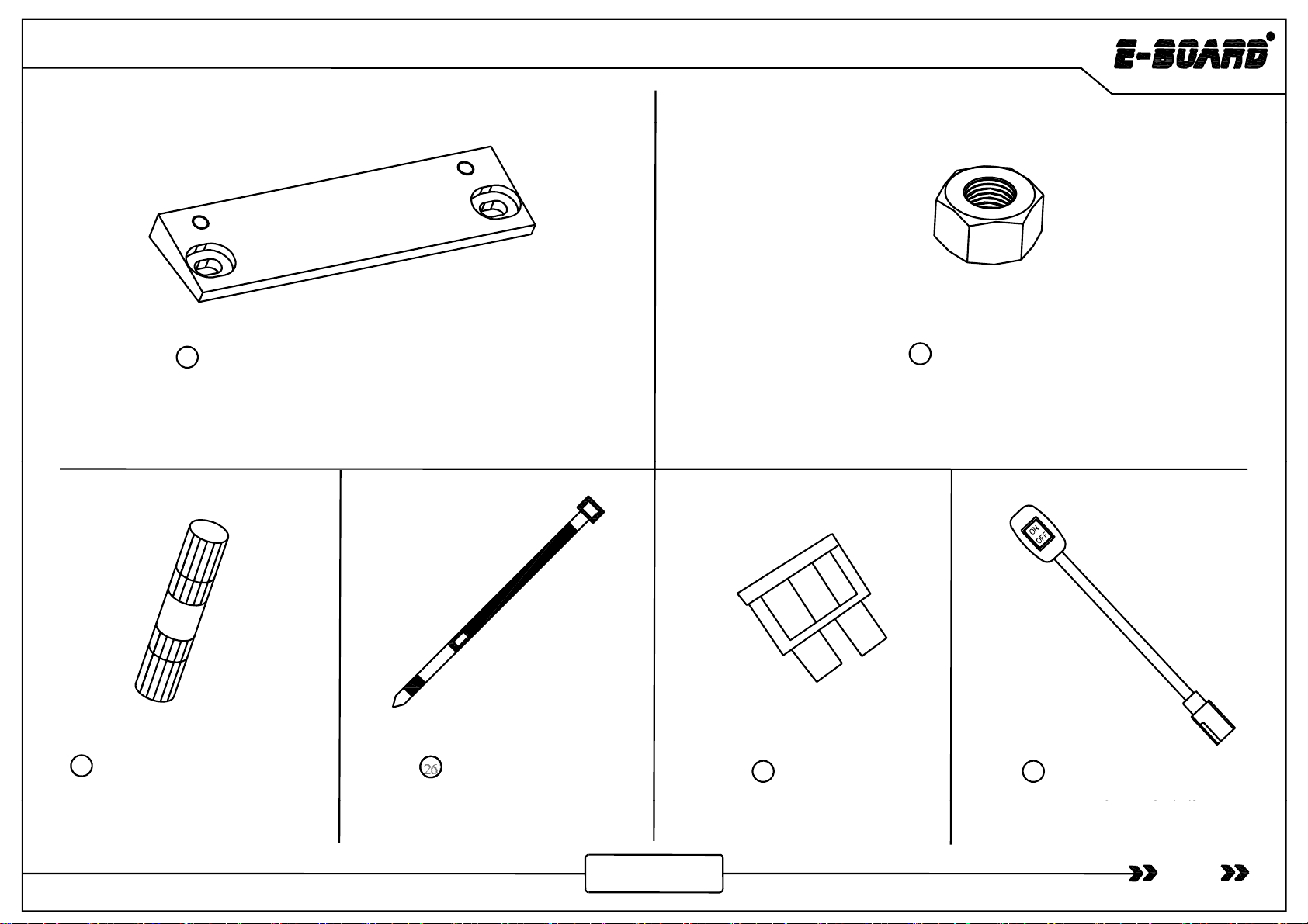
Product Packing List
①
Board Assembly
JP4
×
2
6124101 2
①
-
Board
Assembly
JP4
×
2
6124101
.
2
Board Assembly JP2×2 6124100.2
②- Front Motor Linkage Left ×1
6124100.1LF
③- Front Motor Linkage Right ×1
6124100.1RF
④- Rear Motor Linkage Left 4D×1
6124101.1LB
Rear Motor Linkage Left 2D×1
⑤- Rear Motor Linkage Right4D×1
6124101.1RB
Rear Motor Linkage Right2D×1
03
6124100.1LB 6124100.1RB
www.tmax.biz
JEEP WRANGLER
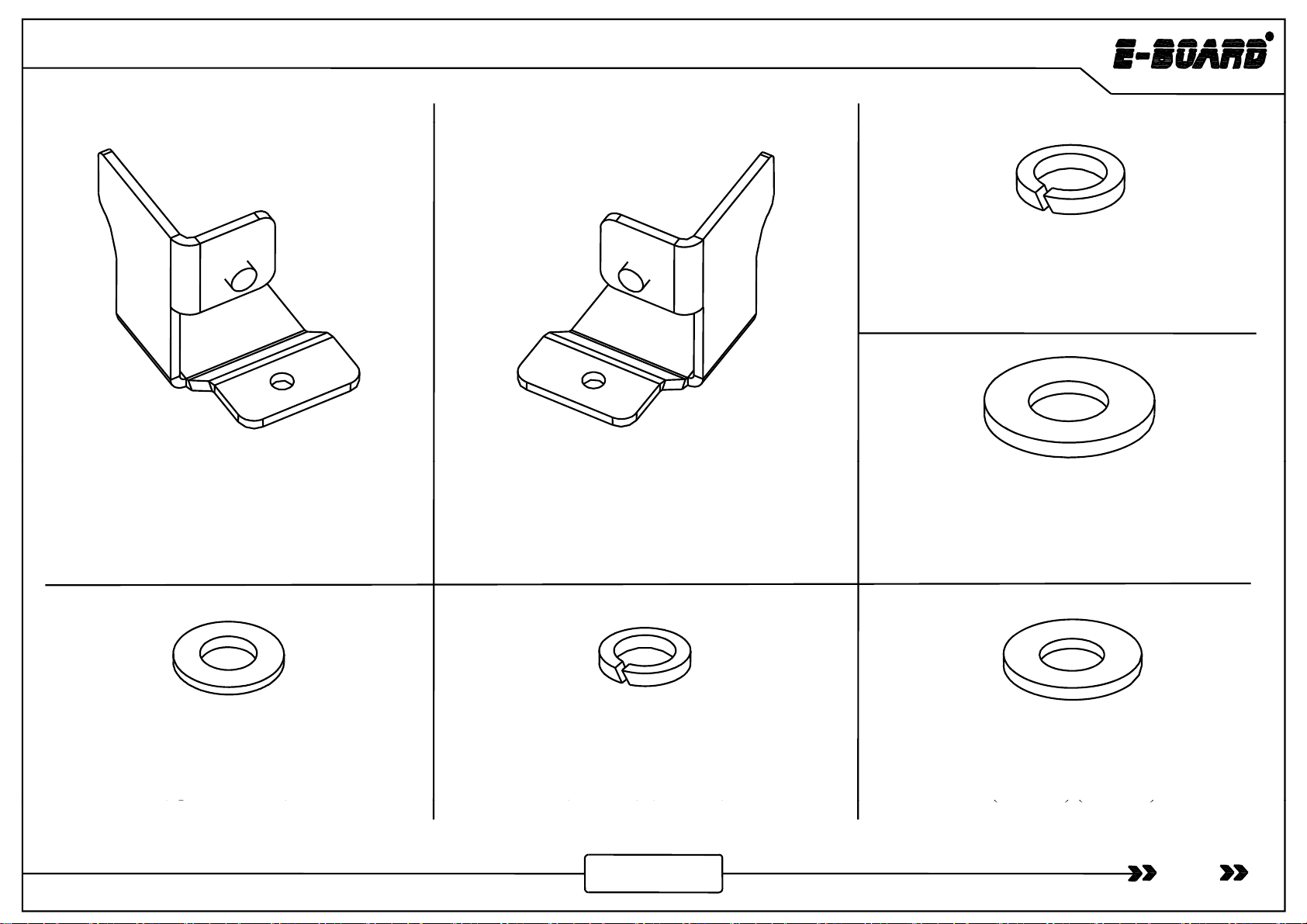
⑧- Spring Washer×2
GB/T93-1987 12
⑥- Motor Protective Plate Left
JP-L×1
6124100.0-2L
⑦- Motor Protective Plate Right
JP-R×1
6124100.0-2R
⑨- Flat Washer Grade A×2
GB/T96.1-2002 12
⑩- Flat Washer×2
GB/T95-1985 8
(
S
p
ecial for 4D
)
⑪- Spring Washer
GB/T93-1987 8
(
2D×18
)
(
4D×16
)
⑫- Flat Washer Grade A
GB/T96.1-2002 8
(
2D×18
)
(
4D×14
)
04
(p
)
(
)
(
)
(
)
(
)
www.tmax.biz
JEEP WRANGLER
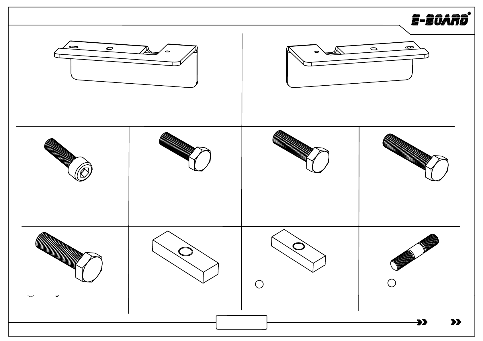
⑬- Mounting Plate Left JP2-L×1 6124110.0-3L
(Special for 2D)
⑭- Mounting Plate Right JP2-R×1 6124110.0-3R
(Special for 2D)
⑮- Socket Cap Screw ×8
GB/T70.1-2000 M6×25
⑯- Hexagon Head Bolt
GB/T5781-86 M8×20
(2D×12) (4D×10)
⑰-Hexagon Head Bolt×2
GB/T5781-86 M8×25
(Special for 4D) ⑱-Hexagon Head Bolt×4
GB/T5781-86 M8×35
⑲
-Hexa
g
on Head Bol
t
×2
⑳
-
M12
Tension Block
×
2
-M8 Tension Block ×2
6124110.0-5
-Stud Bolt A×2
GB/T900-1988 M8×25
21 22
05
⑲
g
GB/T5783-2000 M12×35
⑳
-
M12
Tension
Block
×
2
6124110.0-4 (Special for 2D) (Special for 2D)
www.tmax.biz
JEEP WRANGLER
il
HNt
×
2
- Mount
i
ng P
l
ate JP4×2 6124100.0-1
(Special for 4D)
-
H
ex
N
u
t
×
2
GB/T 6170-2000 M8
(Special for 2D)
2
4
23
- Posi-lock connector
(For signal cable connection)
- Cable Tie×25
GB/T22344-2008 5×300
-Fuse×2
27
26
25 26 - Power Board Switch ×1
6
1241
5
1
.
4
.9
28
06
(2D×2) (4D×4)
www.tmax.biz
6 5..9

JEEP WRANGLER
4D
4D
Thick
m
agne
t
Magnet
2D
Wi d
Mi
I
diMdl
×
2
Magnet
-Controller Assembly×1
6124100.4.4ZJ
29 -
Wi
re
d
M
agnet
i
c
I
n
d
uct
i
on
M
o
d
u
l
e
×
2
-Magnet×4 (4D ×4)
Note: The normal magnets are for the front doors ,and
the thicker ones are for the rear doors.
-Ma
g
ne
t
×2
(
2D ×2
)
3
0
07
www.tmax.biz
g
(
)

JEEP WRANGLER
Protection tube for high
temperature and burning
Four-core waterproof plug
Two-core plug (black)
Two-core plug (red)
(
ii
d
)
(Negative-Black)
Six-core waterproof plug
- Control Input Wire ×1 6124100.4.1
31
(
Pos
i
t
i
ve-Re
d
)
08
www.tmax.biz
JEEP WRANGLER
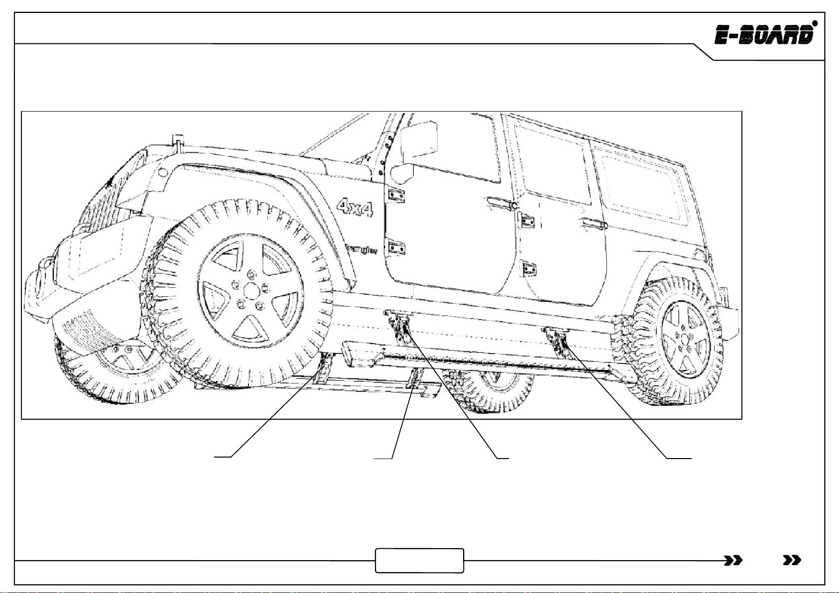
Mechanical Installation
Mechanical
Installation
Front Motor Linkage
Front
Motor
Linkage
Right JP-RF Rear Motor Linkage
Right JP4/2-RB
Front Motor Linkage
Left JP-LF
Rear Motor Linkage
Left JP4/2-LB
Graph of Motor Linkage
09
Graph
of
Motor
Linkage
www.tmax.biz
JEEP WRANGLER
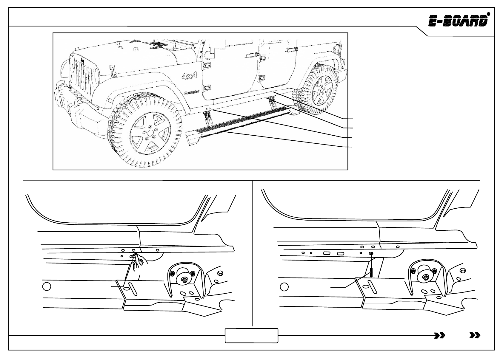
1. Mounting plate installation
2. Tighten bolt for mounting plate
3. Tighten bolt for linkage
4. Board installation
2D 4D
M8 Tension Block Stud Bolt A
22
21
10
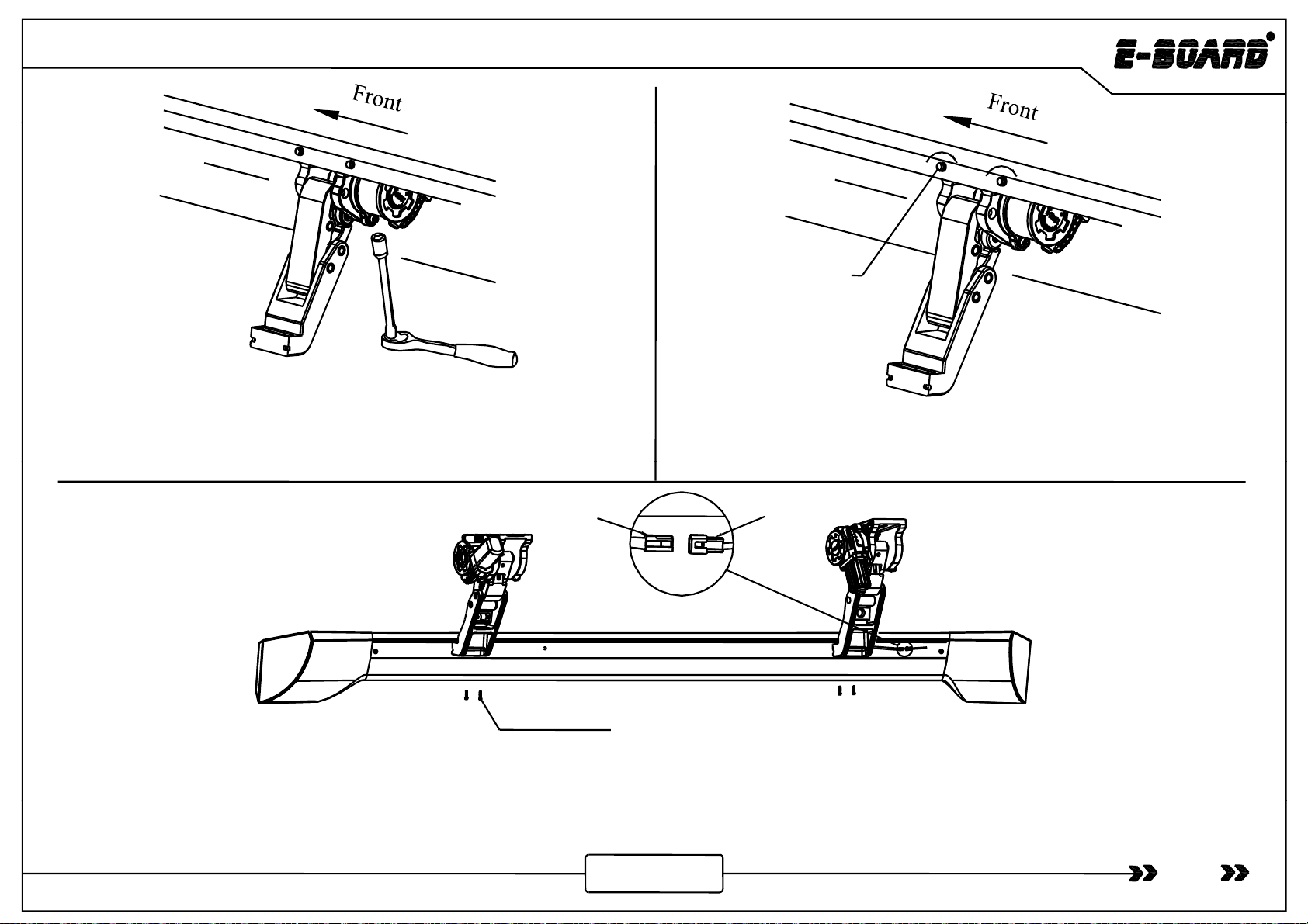
Step 1: Shown as picture, insert the M8 tension block. Step 2: Screw the stud bolt A.
www.tmax.biz
JEEP WRANGLER
4D
2D
4D
Mounting Plate JP4
23
⑫Φ8 Flat Washer Grade A
⑪Φ8 Spring Washer
⑱M8×35 Hexagon Head Bolt
⑪Φ8 Spring
Washer
⑫Φ8 Flat
Washer Grade A
M8 Hex
Nut
⑩Φ8 Flat
Washer
⑪Φ8 Spring
24
Step 3: Fix the mounting plate by hexagon head bolt and hex nut (With
spring washer and flat washer grade A) (Tighten Torque 23Nm) .
Washe
r
⑰M8×25 Hexagon Head Bolt
Step 4: Install the mounting plate as shown in the picture (Tighten
Torque 23Nm) .
Drilling
Position 4D Front
Original hole for
installing motor linkage
Step 5: As shown in the picture drill a new hole on the side skirt based on the original hole (
Dia
of new hole is 6 5mm
-
8 5mm) Please
Original hole as
the base
New drilling hole as the base for
installing motor linkage
11
Step
5:
As
shown
in
the
picture
,
drill
a
new
hole
on
the
side
skirt
based
on
the
original
hole
(
Dia
of
new
hole
is
6
.
5mm
-
8
.
5mm)
.
Please
adjust the hole position due to different vehicles.
www.tmax.biz

JEEP WRANGLER
Drillin
g
Front
g
Position 2D
New drilling hole
for
installing
Original hole for
installing motor linkage
Original hole as the base
New
drilling
hole
for
installing
motor linkage
As shown in the picture, drill a new hole on the side skirt based on the original hole (Dia of new hole is 8.5mm-9.5mm). Please adjust the hole
p
osition due to different vehicles.
p
Installation of Left Front
Motor Linkage
Mounting
⑫
Φ
8
Fl t W h G d A
⑪Φ8 Spring Washer
⑯M8×20 Hexagon Head Bolt
⑪Φ8 Spring Washer
⑫Φ8 Flat Washer Grade A
⑱M8×35 Hexagon Head Bolt
SAhihi hh hdbli
Board base
Mounting
surface of
motor linkage
Step 7: As shown in the picture, pull the board base with 30N force to
ensure that the hole in the mountin
g
surface is corres
p
ondin
g
to the hole in
⑫
Φ
8
Fl
a
t
W
as
h
er
G
ra
d
e
A
12
S
tep 6:
A
s s
h
own
i
n t
h
e p
i
cture , screw t
h
e
h
exagon
h
ea
d
b
o
l
t
i
nto
the thread hole only 3-4 thread to install the motor linkage.
gpg
the side skirt, and then screw the bolt and pre-tighten it (Tighten Torque
6Nm) .
www.tmax.biz

JEEP WRANGLER
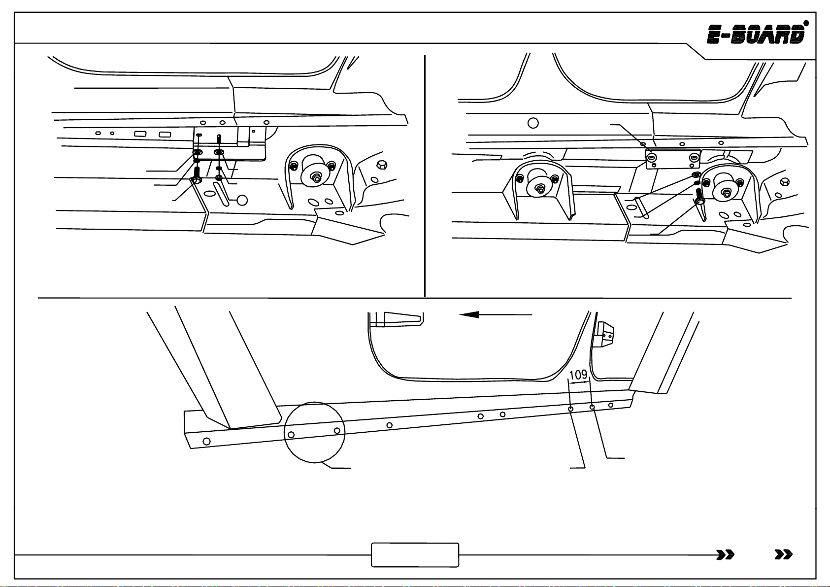
⑫M8×20 Hexagon Head Bolt
Step 8: As shown in the picture, tighten the hexagon head bolt in
the step 6 to install the motor linkage (Tighten Torque 23Nm) .
Step 9: As shown in the picture, tighten the hexagon head bolt
(Tighten Torque 23Nm) .
Installation of
Left Rear Motor
Linkage
⑫
Φ8
Flat Washer Grade A
⑯M8×20 Hexagon Head Bolt
⑪Φ8 Spring Washer
⑫
Φ8
Flat Washer Grade A
Mountin
g
⑫
Φ8
Flat
Washer
Grade
A
⑪Φ8 Spring Washer
⑰M8×25 Hexagon Head Bolt (4D)
⑯M8×20 Hexagon Head Bolt (2D)
Ste
p
10: As shown in the
p
icture, screw hexa
g
on head
b
olt
(
4D
)
/
(
2D
)
⑫
Φ8
Flat
Washer
Grade
A
Board base
g
surface of
motor linkage
Step 11: As shown in the picture, pull the board base with 30N
force to ensure that the hole in the mounting surface is
di h h l
i
hidki dh hbl
13
ppg
()()
(with spring washer and flat washer grade A) into the threaded hole
3-4 thread to install the motor linkage.
correspon
di
ng to t
h
e
h
o
l
e
i
n t
h
e s
id
e s
ki
rt, an
d
t
h
en screw t
h
e
b
o
l
t
and pre-tighten it (Tighten Torque 6Nm) .
www.tmax.biz
JEEP WRANGLER
⑯M8×20 Hexagon Head Bolt
Step 12: As shown in the picture, tighten the hexagon head bolt in
the step 10 to install the motor linkage. (Tighten Torque 23Nm) Step 13: As shown in the picture, tighten the hexagon head bolt.
(Tighten Torque 23Nm)
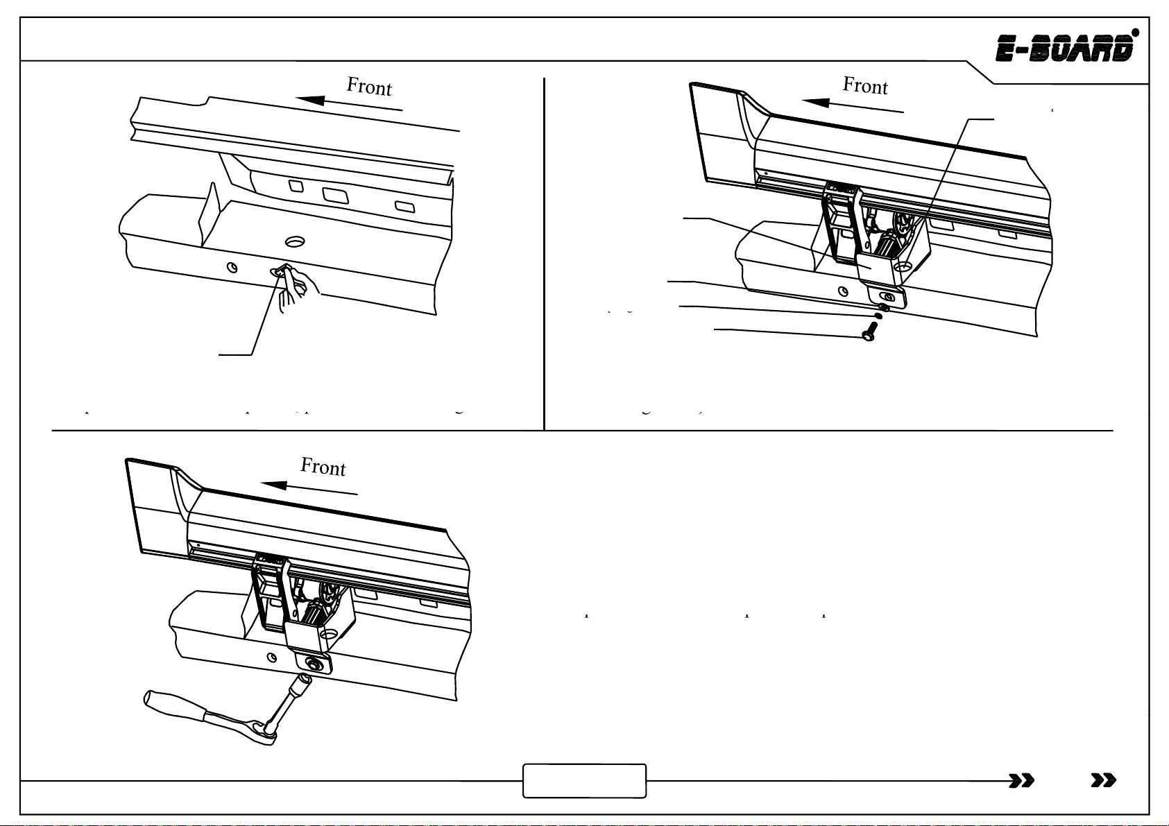
Light belt insert Light belt socket
⑮-M6×25Socket Cap Screw
Step 14:As shown in the picture, tighten socket cap screw to connect board and motor linkage (Tighten Torque 12Nm). Put the light belt into the
14
groove on the back of board after connecting insert and socket. This installation step is only for glare type.
www.tmax.biz
JEEP WRANGLER
Note: Put
p
in of motor
⑥
Motor Protective
p
protective plate JP-L
into this hole.
⑥
Motor
Protective
Plate JP-L
⑨Φ12 Flat Washer
Grade A
⑧
Φ12 S
p
rin
g
Washe
r
⑳M12 Tensioning Block
⑧
pg
⑲M12×35 Hexagon Head Bolt
Ste
p
15: As shown in the
p
icture
,
p
ut in M12 tensionin
g
block.
Step 16: Install motor protective plate JP-L according to above
picture. Screw hexagon head bolt (with spring washer and flat
washer
g
rade A
)
into the threaded hole 3-4 thread.
pp,pg
g)
Ste
p
17: Make the motor
p
rotective
p
late reach to the vehicle bea
m
ppp
and then tighten the ⑲hexagon head bolt.(Tighten Torque 32Nm)
15
www.tmax.biz

JEEP WRANGLER
Status of Power Board Get Back
16
www.tmax.biz

El t i
JEEP WRANGLER
El
ec
t
r
i
c
Installation of
Magnetic
Control
4.Connect white and brown signal wire
with wired magnetic induction module .
Power
Board
Switch
1. Pull out the fuse and
connect the battery wire.
2C tth t l
i
d
ll f ti
i
t th i t d iti
5. Insert back the fuse
and sort out the wires.
Battery
3. Connect motor wire and LED lamp wire.
2
.
C
onnec
t
th
e con
t
ro
l
w
i
re an
d
arrange a
ll
f
unc
ti
on w
i
res
t
o
th
e po
i
n
t
e
d
pos
iti
ons.
Chassis on the right
Controller
Ste
p
1: Find out the control in
p
ut wire and
p
ull out the fuse
(
ensurin
g
p
p
p(g
circuit safety during installation) and connect the positive and
negative pole of wire harness to vehicle battery respectively.
Note: Battery wire can not be modified privately.
17
www.tmax.biz

Front
JEEP WRANGLER
Front
Right Rear
Right
Battery
Front
Front
Right
Controller
Front
Right
Front
Left
Front
Left Rear
Left
Rear
Right Rear
Left
Figure 1 Figure 2
Left side
(upward view)
Figure 1 is the wire harness diagram and figure 2 is the installation diagram.
When install the wire harness, make sure the four connectors are connected with the four motor linkages by
“f t l ft
lft
f tiht d iht”
18
“f
ron
t
l
e
ft
,rear
l
e
ft
,
f
ron
t
r
i
g
ht
an
d
rear r
i
g
ht”
.
www.tmax.biz

JEEP WRANGLER
Φ8 Larger Washer Grade A
Φ8 Spring Washer
I t ll th t ll bl h i th i t ti ht b lt (Ti ht t i 30N )
Controller Assembly M8×20 Hexagon Head Bol
t
I
ns
t
a
ll
th
e con
t
ro
ll
er assem
bl
y as s
h
own
i
n
th
e p
i
c
t
ure,
ti
g
ht
en
b
o
lt
s
(Ti
g
ht
en
t
orque
i
s
30N
m
)
.
The installation of controller assembly for 2D refers to 4D.
www.tmax.biz 19
This manual suits for next models
3
Table of contents
Other T-MAX Automobile Accessories manuals


