Underbody Clamp Operating instructions
(from week 14/2015)
Subject to technical modifications. 14.11.2018
TÜNKERS®Maschinenbau GmbH Am Rosenkothen 8 • D-40880 Ratingen Tel. 02102 4517-0 • Fax 02102 445808 Internet www.tuenkers.de
1. Description
The Underbody clamp is a high-performance tool, which is
designed for clamping tasks in metal processing. It consists of a
pneumatic cylinder, a metal case with front and back attachment
options and a centering mandrel with an integrated tension hook.
The pneumatic cylinder influences on one or two tension hooks
during the clamping process, which clamp the work piece guided
by a platform. The position control of the clamping arm is optional
via an integrated inductive query.
2. Safety
The Underbody clamp is not designed as a ready-to-use
freestanding tool, and is therefore not equipped with its own safety
devices. Only through the proper installation in a manufacturing
system and the establishment of a corresponding safety control
unit are the technical safety requirements fulfilled.
Shut down the Underbody clamp immediately in the event of any
malfunction that is likely to affect personal safety. Maintenance
work may only be performed by properly trained skilled personnel -
while the equipment is shut down.
Ensure that all safety devices are refitted correctly after
maintenance work has been carried out.
Maximum load depends on diameter of dowel pin and geometry of
the hook.
3. Assembly of the Underbody clamp
Installation of the clamp via 4 cheese-head screws on the front
or back support surface.
Create a compressed air supply between the pneumatic
control unit and the clamp (connections "N").
Caution: The use of external flow control valves is
recommended for the fine tuning of the speed of the clamping
process.
If using magnetic switches, assemble and connect these.
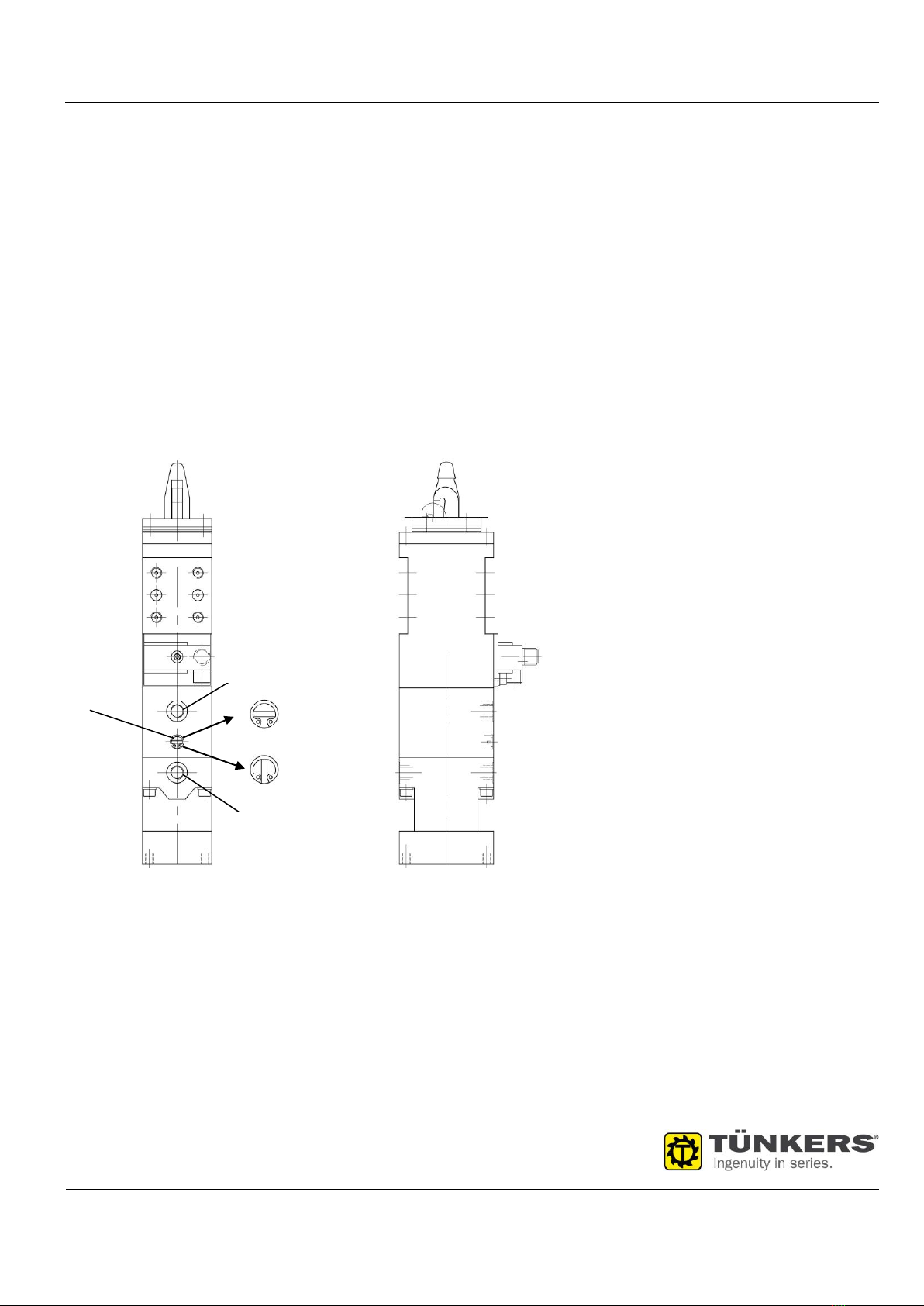
Inductive query (T12)
Attach the electric coupling according to the electric construction
of the pneumatic clamp to the connection plug "C" and tighten.
Attention: When operating a KN 40 UZ version „B“ the adjusting
screw „A“ must be set to position „V“ (see pic. 3) so that the
blocking system is activated.
Caution: An operation with the incorrect or excessive voltage may
result in short circuiting and physical injuries.
The function check of the integrated LED is as follows:
green................... Operating voltage
yellow.................. Clamp open
red ...................... Clamp closed
4. Adjusting the Underbody clamp
Caution! Risk of crushing injuries!
There is danger of fingers being crushed or amputated during
adjustment of the clamping hook! Do not reach into the swivel area
of the clamping hook while the Underbody clamp is operating.
Interrupt the compressed air supply prior to working in the tool
area.
Move the Underbody clamp to the open position, clamping
hook is retracted in centering pin.
Place the work piece on the centering pin and move to the
desired position.
Move the clamp with compressed air to the closed position, so
that the clamping hooks contact the work piece.
If the end position is not shown by the position check of the
switches (clamp closed, LED red), the placement of the work
piece (adjusting plate, base plate) must be corrected
accordingly.
5. Blocking system „B“
KN 40 UZ clamps version "B" are equipped with a mechanical
blocking system acting in „open“-direction. In case of a
spontaneous failure of the compressed air supply, the movement
of the clamp arm in "open" direction will be prevented.
Operating mode:
The blocking system consists of balls which are arranged in a
cone concentric to the piston rod. The balls are pressed into the
cone by spring force. This leads to jamming of the piston rod in
the intended movement direction for opening.
Pic. 2: Blocking system „B“