TÜNKERS ALPHA APH... FUZ B Series User manual

Subject to technical alterations. 28.10.2015
TÜNKERS®Maschinenbau GmbH Am Rosenkothen 8 • D-40880 Ratingen Phone02102 4517-0 • Fax 02102 445808 Internet www.tuenkers.de
Operating Instructions
ALPHA Underbody Clamp
APH… FUZ B
APH… FUZ H

ALPHA Underbody Clamp Operating Instructions
APH… FUZ
----
Subject to technical modifications. 28.10.2015
TÜNKERS®Maschinenbau GmbH Am Rosenkothen 8 • D-40880 Ratingen Phone02102 4517-0 • Fax 02102 445808 Internet www.tuenkers.de
1. Description
The underbody clamp is a high-performance tool, which is
designed for clamping tasks in sheet metal processing. It
consists of a pneumatic cylinder, a metal case with front and
back attachment options and a centering mandrel with an
integrated tension hook.
During the clamping process, the pneumatic cylinder affects
an integrated curve-driven mechanism to increase the
powerwhich triggers the otion f the tension hook. The posi-
tion of the tension hook is controlled via sensing elements
integrated in the housing.
To achieve a longer clamping stroke and to be able to clamp
various material thicknesses, a curve-shaped support plate
is installed and serves as toggle lever bearing. Since this
mechanism is not self-locking, the drive cylinder for the ten-
sion line includes a controlled non-return valve (version "H")
or a locking system (version "B") is added.
2. Safety
The ALPHA underbody clamp was not conceived to be a
complete tool, ready for independent applications and has
therefore not been fitted with safety equipment. The tech-
nical afetyrequirements re only met through its roper installa-
tion in a manufacturing system and the installation of an
appropriate safety control unit.
Should any defects occur that place personnel at risk, the
underbody clamp is to be switched off immediately. Mainte-
nance work may only be carried out by trained specialists
and with the machine shut down.
Ensure that all safety devices are efitted correctly after
maintenance work has been carried out.
Maximum load depends on the diameter of the mandrel and
the dimensions of the hook.
3. Adjustment of ALPHA underbody clamp
Caution! Risk of crushing!
During the adjustment of the tension hook your fingers can
be severed or crushed. Do not reach into the swivel area of
the tension hook while the ALPHA underbody clamp is in
operation. Interrupt the compressed air supply prior to work-
ing in the tool area and remove the supply lines from the
Clamp.
The underbody clamp is designed in a way that the dimen-
sion "Y" matches to the bottom side of the component.
Dimension "X" refers to the thickness of the component,
ideally it is equal to the average thickness of the component
within the expected tolerance range of the component. The
APH… FUZ unit includes an adjusting function X +/- with
which the expected tolerance can be balanced.
- Measure the height of the supporting face in accordance
with the mounting set documentation.
- If necessary, use shims to adapt the supporting face
and/or the connection.
- Max./min. Check the sheet metal thickness using an
appropriate tool(depends on type and design).
Figure 1: APH… FUZ B
Figure 2: APH… FUZ H
„Z“
E
F

ALPHA Underbody Clamp Operating Instructions
APH… FUZ
----
Subject to technical modifications. 28.10.2015
TÜNKERS®Maschinenbau GmbH Am Rosenkothen 8 • D-40880 Ratingen Phone02102 4517-0 • Fax 02102 445808 Internet www.tuenkers.de
To check the roller for safety reasons, demount the
cover plate (B) by releasing the screws.
Bring the underbody clamp to its open position, the
tension hook is swivelled into the centering mandrel;
the roller is in its lower position.
Place the workpiece on the centering mandrel and
move it to the desired position.
Move the underbody clamp to its clamping position,
the tension hook contacts the workpiece, roller (F) is in
the central position of the support plate (E), see detail
"Z".
Fasten cover “B” with screws.
4. Locking system "B"
The version "B" ALPHA-clamps are equipped with a me-
chanical locking system acting in „Open“-direction. If the
compressed air supply fails spontaneously, movement of the
tension hook in the "open" direction will be prevented.
The applied holding force is at least
50 % of the nominal force.
IMPORTANT:
Exceeding of this holding force can destroy internal compo-
nents or can cause shorter lifetime, even if the holding func-
tion applies for a short time.
How it works:
The locking system consists of balls concentrically arranged
around the piston rod in a cone. They are pressed into the
cone by spring force. This causes the piston rod to be
clamped in the direction of movement designated for open-
ing.
The locking mechanism is released automatically by the
pneumatic control of the clamp in "open" direction.
If it has been depressurized, the position of the tension hook
is held by clamping the piston rod on the return side.
Please find the holding forces in the range of "power stroke"
in the referring data sheets of the ALPHA-underbody
clamps.
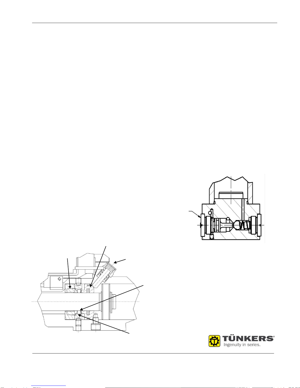
Unlocking of the clamp (version "B")
For maintenance, the locking mechanism can be unlocked
manually. For this purpose, actuate the manual unlocking
device, designed as pressure switch on the rear side using a
suitable tool (screwdriver, Allen key).
If the actuating plunger (A) has been pressed in for approx.
10 mm, the tension hook can simultaneously be brought to
the desired position.
Caution! In case the manual unlocking device is actuated,
the tension hook can move unexpectedly.
5. Holding function and unlocking of the version
"H" clamp
For the purpose of safety-relevant applications, the ALPHA
underbody clamp is equipped with a pneumatic holding func-
tion (“H“). This pneumatic self-locking function keeps the
drive cylinder in the „clamp closed“ position via an unlocka-
ble non-return valve integrated into the cylinder bottom. Due
to this pressurization, the clamp can not be opened automat-
ically. The pneumatic self-locking device is released by
changing over of the main valve or by manual actuation of
the non-return valve "A". Manual operation is only allowed
without compressed air supply! A special, external pneumat-
ic control is not required.
To unlock the clamp manually
remove the cover plate „B“ and push the tension hook to its
“open” position using an appropriate tool.
Unlocking piston
Manual unlocking
Ball
Spring
Cone
Figure 3: Locking system "B"
Figure 4: Holding function "H"
Manual
unlocking
device

ALPHA Underbody Clamp Operating Instructions
APH… FUZ
----
Subject to technical modifications. 28.10.2015
TÜNKERS®Maschinenbau GmbH Am Rosenkothen 8 • D-40880 Ratingen Phone02102 4517-0 • Fax 02102 445808 Internet www.tuenkers.de
6. Assembly of ALPHA underbody clamp
Install the clamp by means of cylinder screws and dowel
pins at the front and the rear connecting side.
Inductive sensor T12:
Depending on the electrical design of the pneumatic ten-
sioner (see circuit diagrams), place the electric coupling on
the connector "C" and screw it on.
Caution: Operation with incorrect or excessive voltage may
result in short circuiting and personal injuries.
Perform the functional inspection of the integrated LED as
follows:
Green.................. operating voltage
Red.....................Clamp closed
Yellow.................Clamp open
7. Replacement of the sensor cartridge
Remove the sensor cartridge by releasing screw “D”.
Insert a new sensor cartridge and fasten it.
8. Maintenance
The ALPHA underbody clamp is designed for large-batch
production and is equipped with low-maintenance bearings
and guides. Based on the enclosed design, special mainte-
nance of the underbody clamps is not required.
Caution: Cleaning with a steam-jet cleaner or dry ice causes
damage of the underbody clamp.

-
Sensing set Inductive switch, 1 output
T12
Subject to technical modifications. 28.10.2015
TÜNKERS®Maschinenbau GmbH Am Rosenkothen 8 • D-40880 Ratingen Phone02102 4517-0 • Fax 02102 445808 Internet www.tuenkers.de
Technical Specifications
Inductive switch (Standard version)
Short circuit proof
Rated voltage 10-30 V
Working current 32 mA ( one initiator connected with PLC)
Closer PNP exit
yellow
- open/back -
red
- closed/forward -
green
This manual suits for next models
1
Other TÜNKERS Industrial Equipment manuals
Popular Industrial Equipment manuals by other brands

Danfoss
Danfoss DTW 300 SP Installation, service and user manual

Aerotech
Aerotech PRO225SL Hardware manual

HEIDENHAIN
HEIDENHAIN AE LC 4x3 Replacing Instructions

Sacmi
Sacmi BTA 900 instruction manual

Eaton
Eaton NZMN3-A400-S07-DC Instruction leaflet

Northern Industrial Tools
Northern Industrial Tools 998001 owner's manual