70 60 50 40 30 20 10 0 -10 -20
Outdoor Temperature (F)
150
140
130
120
110
100
90
80
70
60
Supply Temperature (F)
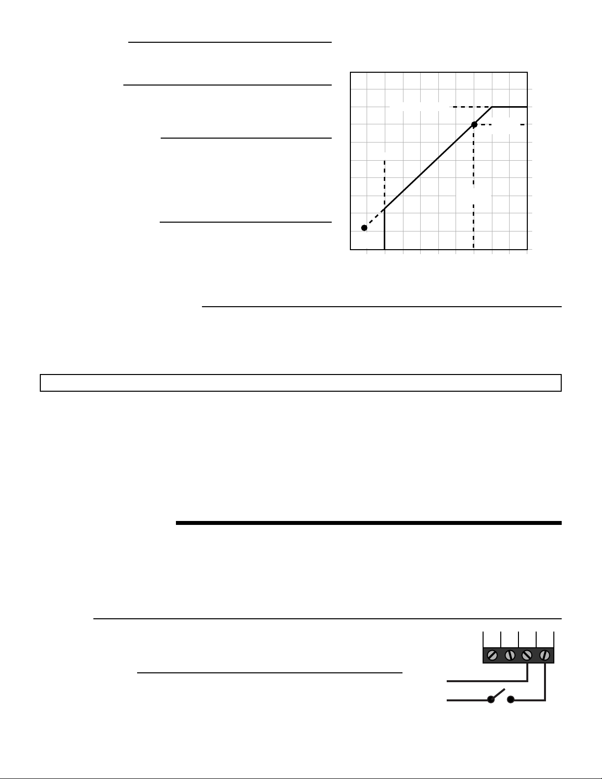
Mix Maximum
Outdoor
Design
Mix
Design
Outdoor Reset
WWSD
Starting
Point
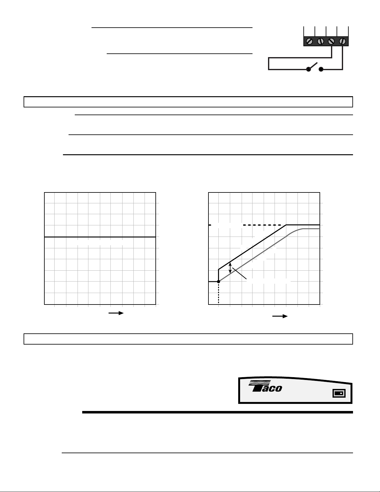
Setpoint and Delta T Mode of Operation
In certain applications, it is desirable to maintain a fixed supply water temperature. This type of application is a setpoint application.
Examples of setpoint applications include heat pump loops, reheat coils and floor warming.
In specialized applications, such as snow melting, it is desirable to limit the rate of temperature increase in the system from the system‘s
starting temperature to its operating setpoint. This is desired in order to prevent thermal shock of the system. This type of application is
a Delta T application.
If the RMC is to operate as a setpoint control, the Outdoor Design temperature must be set to OFF and the Mixing Target temperature
must be set to the desired temperature.
If the RMC is to operate as a Delta T control, a mixing return sensor must be installed, the Outdoor Design temperature must be set to
OFF and both the Delta T Max setting and the Mixing Target temperature must be set to the desired temperature.
In both of these applications, the outdoor sensor is not to be installed
SEQUENCE OF OPERATION
When the RMC receives a Demand, the system pump is turned on.
If the Delta T Max setting is set to OFF, the variable speed injection pump is operated to maintain the mixing supply sensor at the
Mixing Target temperature set by the installer.
If the Delta T Max setting is not set to off, the variable speed injection pump is operated to maintain the mixing supply sensor at either
the Mixing Return temperature plus the Delta T Max setting or the Mixing Target temperature set by the installer whichever is lower.
The boiler contact operates as described in the Boiler Operation section. The RMC also provides boiler protection as described in the
Boiler Operation section.
DEMAND
The RMC requires a demand signal before it will begin operation. The RMC can use
either a powered or an unpowered demand signal. Once a demand signal is received, the
RMC displays the demand pointer in the display and operates as described above.
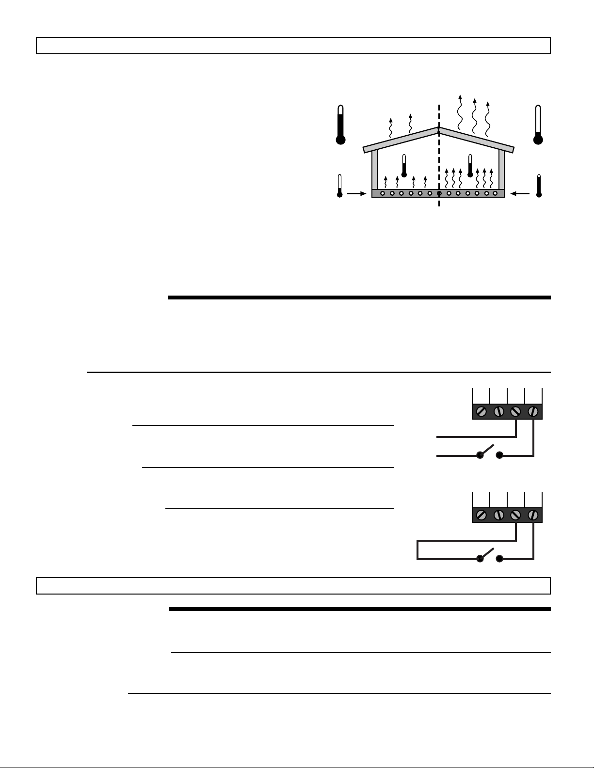
Powered Demand
The RMC recognizes a Powered Demand Signal when 24 V (ac) is applied across the
Com and Heat Dem terminals.
Outdoor Design
The Outdoor Design temperature is the average coldest day of the
year for the area in which the building is located.
Design Supply
The Design Supply temperature is the supply water temperature that
is required to heat the building when the outdoor air temperature is
as cold as the Outdoor Design temperature.
Maximum System Supply
Some systems, such as hydronic radiant floor heating, may require the
maximum supply water temperature to be limited in order to protect
certain system components from high temperatures. The RMC has a
Maximum Supply setting that can be used to limit the maximum tem-
perature that the control is allowed to use for a Mixing Target (MIX TRG)
temperature.
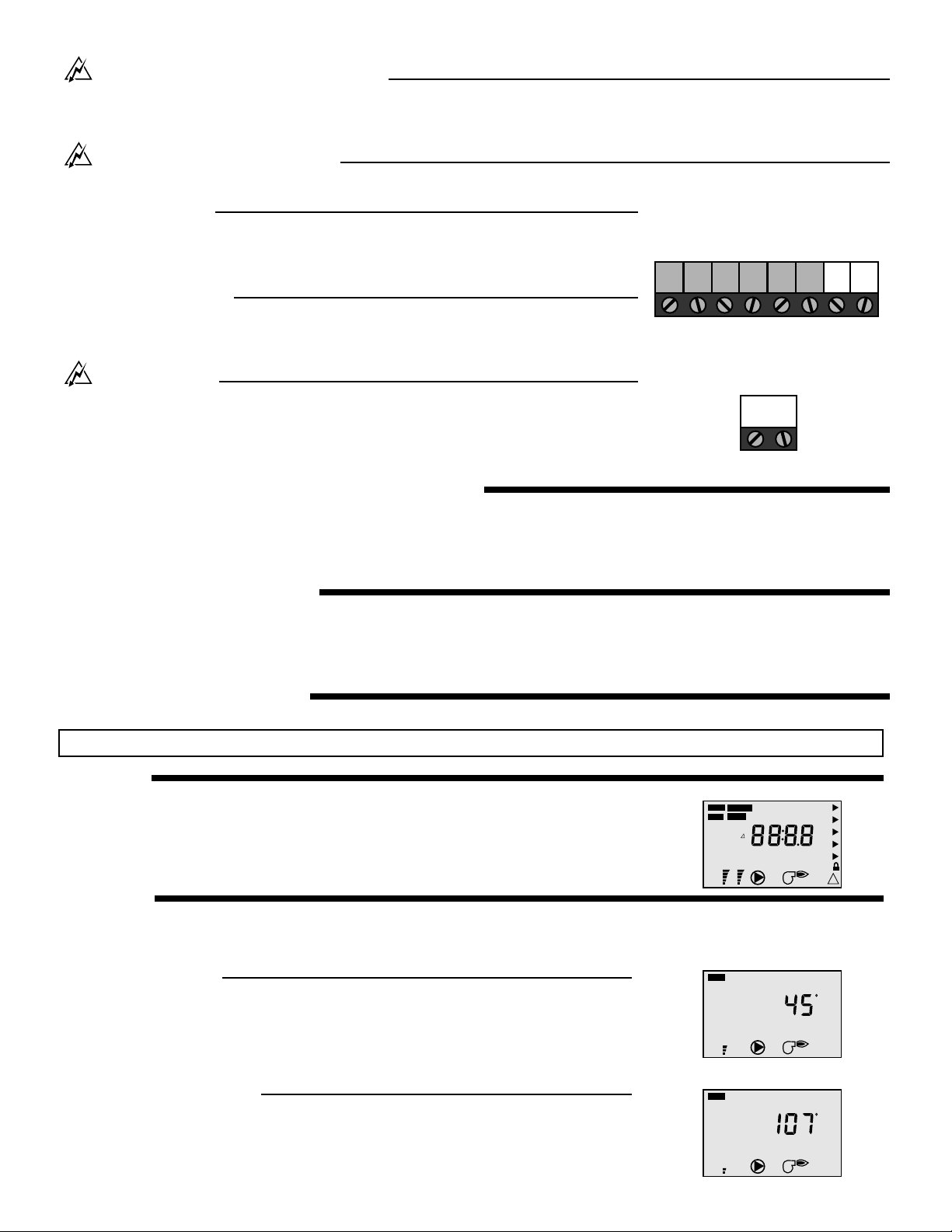
Minimum System Supply
Some applications, such as floor warming, may require the minimum
supply water temperature to be limited in order to provide a certain
level of occupant comfort. The RMC has a Minimum Supply setting that
can be used to limit the minimum temperature that the control is al-
lowed to use for a Mixing Target (MIX TRG) temperature. This minimum
applies as long as the RMC has a demand and is not in WWSD.
Warm Weather Shut Down (WWSD)
When the outdoor temperature is warmer than the WWSD setting, the RMC turns off the boiler and the variable speed injection
pump. If a demand is received while the RMC is in a WWSD, the RMC indicates that the demand has been received by displaying
the Demand pointer however, the MIX TRG remains as “- - -“ The RMC has a freeze protection feature that does not allow the
supply water temperature to drop below 35°F (2°C) as long as there is a mixing demand signal.
Com Heat
Dem
Boil Out
Powered
Demand
C
24 V (ac)
RSwitch