LIMITED WARRANTY STATEMENT
Taco, Inc. will repair or replace without charge (at
the company’s option) any Taco High Efficiency
circulator or circulator part which is proven
efective un er normal use within three (3) years
from the ate of manufacture.
In or er to obtain service un er this warranty, it
is the responsibility of the purchaser to promptly
notify the local Taco stocking istributor or Taco
in writing an promptly eliver the subject pro uct
or part, elivery prepai , to the stocking istrib-
utor. For assistance on warranty returns, the
purchaser may either contact the local Taco
stocking istributor or Taco. If the subject pro -
uct or part contains no efect as covere in this
warranty, the purchaser will be bille for parts
an labor charges in effect at time of factory
examination an repair.
Any Taco pro uct or part not installe or operate
in conformity with Taco instructions or which
has been subject to misuse, misapplication, the
a ition of petroleum-base flui s or certain
chemical a itives to the systems, or other
abuse, will not be covere by this warranty.
If in oubt as to whether a particular substance
is suitable for use with a Taco pro uct or part, or
for any application restrictions, consult the
applicable Taco instruction sheets or contact
Taco at (401-942-8000).
Taco reserves the right to provi e replacement
pro ucts an parts which are substantially similar
in esign an functionally equivalent to the
efective pro uct or part. Taco reserves the right
to make changes in etails of esign, construc-
tion, or arrangement of materials of its pro ucts
without notification.
TACO OFFERS THIS WARRANTY IN LIEU OF
ALL OTHER EXPRESS WARRANTIES. ANY
WARRANTY IMPLIED BY LAW INCLUDING
WARRANTIES OF MERCHANTABILITY OR
FITNESS IS IN EFFECT ONLY FOR THE DURA-
TION OF THE EXPRESS WARRANTY SET
FORTH IN THE FIRST PARAGRAPH ABOVE.
THE ABOVE WARRANTIES ARE IN LIEU OF
ALL OTHER WARRANTIES EXPRESS OR
STATUTORY OR ANY OTHER WARRANTY
OBLIGATION ON THE PART OF TACO.
TACO WILL NOT BE LIABLE FOR ANY SPE-
CIAL INCIDENTAL INDIRECT OR CONSE-
QUENTIAL DAMAGES RESULTING FROM THE
USE OF ITS PRODUCTS OR ANY INCIDENTAL
COSTS OF REMOVING OR REPLACING
DEFECTIVE PRODUCTS.
This warranty gives the purchaser specific
rights, an the purchaser may have other rights
which vary from state to state. Some states o
not allow limitations on how long an implie
warranty lasts or on the exclusion of inci ental
or consequential amages, so these limitations
or exclusions may not apply to you.
Do your best work.®
TACO INC., 1160 Cranston Street, Cranston, RI 02920 Telephone: (401) 942-8000 FAX: (401) 942-2360.
TACO (Canada) Ltd., 8450 Lawson Roa , Unit #3, Milton, Ontario L9T 0J8. Telephone: 905/564-9422. FAX: 905/564-9436.
Visit our web site at: http://www.taco-hvac.com
Printe in USA
Copyright 2013
TACO, Inc.
8
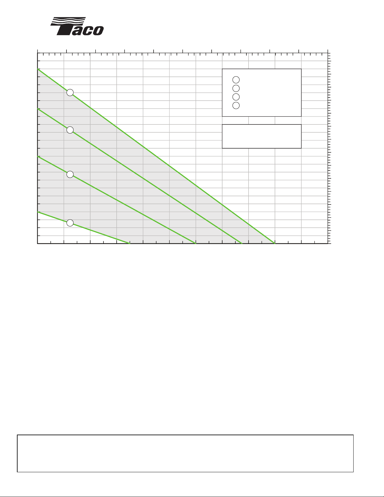
FLOW - GPM
0 2 4 6 810121416182022
0
1
2
3
4
5
6
7
8
9
10
11
12
13
14
15
16
17
18
19
20
21
22
23
24
FLOW - M3/H
0.0 0.5 1.0 1.5 2.0 2.5 3.0 3.5 4.0 4.5 5.0
0.0
0.5
1.0
1.5
2.0
2.5
3.0
3.5
4.0
4.5
5.0
5.5
6.0
6.5
7.0
VT2218 PERFORMANCE CURVES
TOTAL HEAD - FEET
TOTAL HEAD - METERS
Shaded area is variable
speed operating range.
Min. Speed 1 (9W)
Speed 2 (24W)
Speed 3 (40W)
Max. Speed 4 (58W)
1
2
3
4
1
2
3
4