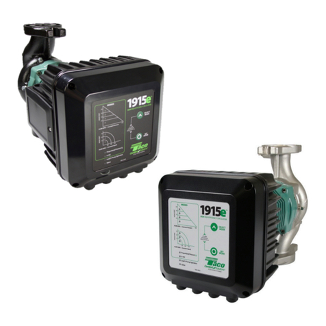
-2-
WARNING!
Installation and use of this product requires experience and knowledge of this or similar products. Persons withreduced
physical, mental or sensory capabilities must not use this product, unlessproperly instructed and supervised. Children
must not be allowed to play with this product.
WARNING!
Prior to installation and commissioning, read these instructions first.Installation and operation must comply with local regulations.
TABLE OF CONTENTS
1. Symbols & conventions used in this document...3
1.1. Abbreviations and conventions........................................ 3
2. Introduction .......................................................................................3
Section 1 - Installation and Operation.........................4
3. General Uses.......................................................................................4
4. Safety........................................................................................................4
5. Pump Description..........................................................................5
6. Use ..............................................................................................................5
7. Pumped Fluids..................................................................................5
8. Pump Installation ..........................................................................5
8.1.1 Motor Rotation Procedure................................................. 6
8.1.2 After Installation into piping............................................ 7
9. Electrical Connections ...............................................................8
10. Setup and Operation...................................................................9
10.1 Control Panel Layout.............................................................. 9
10.2 Switching the Pump On and O.................................... 9
10.3 Pump Functions........................................................................ 9
10.4 Operation and Mode Selection.....................................10
10.5 Mode Description..................................................................10
10.6 Restoring Factory Settings ...............................................11
10.7 Minimum Speed Adjustment.........................................11
10.8 Parallel Pumping.....................................................................12
11. Specications .................................................................................14
11.1 Application.................................................................................13
11.2 Electrical Ratings.....................................................................14
11.3 Standards, Protection and Flange Conn..................15
11.4 Materials of Construction..................................................15
Section 2 - Controller (VFD) Operation ....................16
12. Features...............................................................................................16
12.1 Specications ..........................................................................17
12.2 BACnet Specications ........................................................17
12.3 Modbus Specications .......................................................17
12.4 Ethernet Specications.......................................................17
12.4 Mode Selection Switch.......................................................17
12.5 Analogue Signals....................................................................18
12.6 Relay Specications ..............................................................18
13. Controller Layout......................................................................18
13.1 Connection considerations...........................................19
13.2 Connection examples ......................................................19
14. Control modes and priorities..........................................20
14.1 Priority of settings ...............................................................20
14.2 Control variables..................................................................21
14.3 Module mode selection..................................................22
14.4 Mode 1.......................................................................................23
14.5 Mode 2.......................................................................................27
14.6 Mode 3 & 4 ..............................................................................28
15. Relay output .................................................................................31
16. Network............................................................................................31
16.1. Bus topology.........................................................................32
16.2. Connecting to pump ad-hoc......................................32
16.3. Connecting to pump via router................................32
16.4 Local Network Setup, Display & Diagnostics......32
17. BACnet................................................................................................39
17.1 BACnet MS/TP communication .................................39
17.2 Data Link LAYER Option...................................................39
17.3 Device Address Binding ..................................................40
17.4 Network Options .................................................................40
17.5 Network Security Options..............................................40
17.6 Character Sets Supported..............................................40
17.7 Supported BACnet Interoperability .........................40
17.8 Analog Inputs ........................................................................41
17.9 Analog Outputs....................................................................41
17.10 Binary Inputs........................................................................42
17.11 Binary Outputs ...................................................................42
18. Modbus...................................................................................................43
18.1 Modbus Related Interface .............................................43
18.2 Modbus Topology...............................................................43
18.3 Connection to Modbus...................................................44
19. Fault nding...................................................................................51
19.1 Error codes...............................................................................51
Performance Curves.............................................................................53
Hydronic Institute Energy Ratings...........................................55
Limited Warranty Statement ........................................................56
NOTE: This is an interactve manual. Clicking on a section below will take you directly to the page.
Click on this icon to return to the Table of Contents
