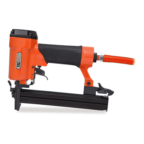
tacwise A6422V User manual

FASTENING TOOLS FOR THE PROFESSIONALFASTENING TOOLS FOR THE PROFESSIONALFASTENING TOOLS FOR THE PROFESSIONAL
OPERATOR’S MANUAL
23G Headless Pinner
A6422V

FASTENING TOOLS FOR THE PROFESSIONAL
32
FASTENING TOOLS FOR THE PROFESSIONAL
3
FIG. B - CONNECTING A TOOL TO THE AIR SUPPLY
2
6
4
1
NAILER
NAGLER
CLOUEUSE
CLAVADORA
CHIODATRICE
OILER
ÖLER
GRAISSEUR
LUBRICADOR
LUBRIFICATORE
FILTER
FILTER
FILTRE
FILTRO
FILTRO
AIR SUPPLY
LUFTZUFUHR
ALIMENTATION EN AIR
SUMINISTRO DE AIRE
ALIMENTAZIONE ARIA
REGULATOR
REGLER
RÉGULATEUR
REGULADOR
REGOLATORE
AIR HOSE
LUFTSCHLAUCH
TUYAU D’AIR
MANGUERA DE AIRE
TUBO DELL’ARIA
QUICK CONNECTOR
SCHNELLVERBINDER
RACCORD RAPIDE
CONECTOR RÁPIDO
CONNETTORE RAPIDO
3
FIG. A
5
IMPORTANT
Please make certain that the person who is to use
this equipment carefully reads and understands these
instructions before starting operations.

4 5
FASTENING TOOLS FOR THE PROFESSIONAL
FIG. C - LOADING THE FASTENERS FIG. D - AIR DEFLECTOR
FIG. E - TRIGGER LOCK
1
2
3
5
EN 23G Headless Pinner A6422V
Congratulations!
On the purchase of your Tacwise power tool. Your tool will perform
to your satisfaction for a long time if handled in accordance with our
Safety and Operating instructions.
Save this manual for future reference
Technical Data
Characteristic Value
Minimum operating air pressure 60psi
Maximum operating air pressure 100psi
Nail length range 12mm (1/2") - 22mm (7/8")
Nail size 23GA Brads
Magazine capacity 100
Air inlet 1/4" NPT
Air consumption 0.6 CFM @ 90psi
Weight 0.8kgs (1.8lbs)
Vibration emission level* 2.35m/s2
* The declared vibration emission level represents the main
applications of the tool. However if the tool is used for different
applications, with different accessories or poorly maintained, the
vibration emission may differ. This may significantly increase
exposure level over the total working period.
CE – Declaration of Conformity
23G Headless Pinner A6422V
Tacwise declares that this power tool has been designed in
compliance with the Regulations and Standards of the
European Directives.
Quality Department, Tacwise Group Plc – UK
WARNING! Before Use Carefully Read And Understand
All Instructions.
Failure to do so could result in fire and/or serious personal injury.
For any queries relating to safety matters on this power tool, please
email [email protected].
Unpacking
• Carefully remove the tool and accessories from the box.
• Inspect the tool carefully to make sure no breakage or damage
occurred during transit.
• If any parts are damaged or missing, please email
until the missing or damaged parts are replaced. Failure to do so
could result in a personal injury.
• Whilst every effort has been made to ensure accuracy of
information contained within this manual, the Tacwise policy is
one of continuous improvement to our products and as such
we reserve the right to change the product specification without
prior notice.
General Safety Instructions
Important. Tacwise recommends that this power tool should not
be modified or used for any application other than that for which
it was designed. Any such alteration or modification is misuse and
could result in a hazardous condition leading to a personal injury. If
you are unsure of its relative applications do not hesitate to contact
us and we will advise you.
Work Area
• Keep your work area clean and well lit. Cluttered benches and
dark areas invite accidents.
• Keep children and pets away. All visitors should be kept a safe
distance from work area.
• Secure work. Use clamps or a vice to hold work. This frees both
hands to operate the power tool.
Safety Warnings & Cautions
• Never use oxygen combustible gases, bottled gases or high
pressure compressed gas as a power source for this tool.
The tool may explode and cause serious injury.
• Outdoor extension cords. When air compressor is used
outdoors, use only rounded jacket extension cords intended for
outside use. See manufacturer’s manual for the AWG required for
the compressor’s amperage draw.
• Pay attention to air hose and their connections. Don’t trip over
hoses. Make sure all connections are tight.
• Use the correct air connector. The connector on the tool must
not hold pressure when the air supply is disconnected. If the
wrong fitting is used, the tool can be charged with air after being
disconnected and still be able to drive a fastener.
• When connecting the air. The tool may possibly fire the
fasteners as soon as you plug it in to the air hose. Therefore,
remove all the fasteners before connecting to the air.
• Do not depress the trigger when loading.
• If the fasteners are jammed. Disconnect the tool from the air
and remove the jammed fasteners.
• Stay alert. Always watch what you are doing and use common
sense. Do not operate a power tool when you are tired or under
the influence of medication, alcohol or drugs.
• Wear proper clothing. Do not wear loose clothing or
jewellery that can catch in moving parts. Non-slip footwear is
recommended. Contain long hair and roll long sleeves above
the elbow.
• Do not over reach or use on unstable surfaces. Keep proper
footing and balance at all times.
• Use safety equipment. Dust mask, non-skid safety shoes,
hard hat, or hearing protection must be used for appropriate
conditions. Wear CE approved safety goggles at all times. Normal
spectacles only have impact resistant lenses; they are NOT safety
glasses.
• DO NOT use on hard surfaces such as rock, concrete, masonry,
bricks or steel. Personal injury or damage to the power tool
could result.
• Stored power tools. When not in use, all power tools should be
stored in a dry, locked cupboard, out of the reach of children and
other untrained persons.
• Recommended accessories. Use only accessories that are
recommended by the manufacturer for your model. Accessories
that may be suitable for one tool may create a risk of injury when
used on another tool.
• Beware of hidden danger. Always make sure there is no danger
of hitting any hidden power cables, water or gas pipes.
• Always assume that the tool is loaded with fasteners.
Handling the tool without care could result in an unexpected
firing of fasteners and lead to personal injury.
• Do not activate the power tool unless it is in contact with the
work piece. Serious injury can result if you depress the
safety lock pin on nose/contact trip with your fingers, or by
improper operation.

6 7
FASTENING TOOLS FOR THE PROFESSIONAL
• Never point any power tool at yourself or at any other
person. While working, hold the tool in such a way that no
injuries can be caused to the head or to the body in the event
of possible recoil.
• Do not drive fasteners on top of other fasteners.
• Do not use this tool to fasten electric cables. This tool is not
designed for the installation of electric cabling and may damage
electric cables which could lead to injury by electric shock or
fire hazards.
Features (Fig. A)
1. Trigger
2. Quick Release Plug (Euro Fitting)
3. Magazine Release Latch
4. Magazine
5. Trigger Lock Mechanism
6. Air Deflector
Set up
Your air tool is fully assembled when you receive it. Before using it,
attach the air line and desired air system accessories. See Fig. B for
the recommended accessories and connection order. Be sure the
air hose is de-pressurised when installing or removing adaptors to
the air line.
Connecting The Tool To An Air Supply (Fig. B)
• Determine if the tool needs oil and, if necessary, place two
drops of oil in the air plug as shown in Fig. B. If you are using an
automatic in-line oiler, check and add oil if necessary.
• Turn the compressor on and set the regulator to the proper
pressure for the size and type of fastener being used.
• Connect the tool to the air supply.
Loading The Tool With Nails (Fig. C)
• Squeeze latch on rear of magazine to release moveable part (1).
• Place a strip of fasteners along channel, positioning fasteners at
the bottom of the open magazine channel.
• Slide the magazine shut until the magazine release latch clicks.
Trigger Lock (Fig. E)
• Located behind the trigger is the trigger lock mechanism. The
tool will not fire when the lock is positioned directly behind the
trigger.
• To unlock the trigger, simply rotate the lock mechanism to either
side as shown. This will allow the trigger to be depressed.
Operating The Tool
• Connect the tool to the air supply. Make sure the air pressure is
in correct range denoted in section of TECHNICAL DATA.
• Load fasteners as directed in the section called LOADING THE
FASTENERS.
• Hold the body and press the drive guide to work surface, be sure
the tool is straight and then gently depress the trigger to drive
the fastener.
• Lift the tool off the work surface.
NOTE: The air deflector (Fig. D) is directional and can be rotated
through 360°.
Removing a Jammed Fastener
NOTE: You must remove any jammed fasteners before using the tool
any further. If you continue to try and fire a fastener while the tool is
jammed, you could cause damage to the mechanism.
• Disconnect tool from the compressed air system
• Remove any unused fasteners from the magazine channel, this
should clear the jammed fastener(s).
• If a fastener is jammed in the drive guide, place the tool on
a solid surface. Using a punch, or a screwdriver, carefully tap
the stuck fastener out of the drive guide.
Regular Maintenance
• Frequent, but not excessive, lubrication is required for best
performance. Oil added through the airline connection will lubricate
internal parts. An automatic airline oiler is recommended but oil
may be added manually before every operation or after about
1 hour of continuous use. Only a few drops of oil at a time are
necessary. Too much oil will collect inside the tool and be blown
out during the exhaust cycle. ONLY USE PNEUMATIC TOOL OIL.
Do not use detergent oil or additives, as these lubricants will cause
accelerated wear to the seal in the tool.
• Use a small amount of oil on all moving surface and pivots.
• Dirt and water in the air supply are major causes of pneumatic
tool wear. Use a filter/oiler for better performance and longer
life. The filter must have adequate flow capacity for the specific
application. Consult the manufacturer’s instructions for proper
maintenance of your filter.
• Keep tools clean for better and safer performance. Use
non-flammable cleaning solutions (CAUTION: Such solutions may
damage O-ring and other tool parts) only if necessary - DO NOT
SOAK.
PROBLEM CAUSE OF PROBLEM SOLUTION
Air leaking at trigger area 1. O-ring in trigger valve is damaged.
2. Trigger valve head is damaged.
3. Trigger valve stem, seal or O-ring
is damaged.
1. Check and replace O-ring.
2. Check and replace trigger valve head.
3. Check and replace trigger valve stem,
seal or O-ring.
Air leaking between body and front plate Damaged piston O-ring or bumper Check and replace O-ring or bumper
Air leaking between body and cylinder cap 1. Screw loose.
2. Damaged seal.
1. Tighten screws.
2. Check and replace seal.
Blade driving fastener too deeply 1. Worn bumper.
2. Air pressure is too high.
1. Replace bumper.
2. Adjust the air pressure.
Runs slowly or has power loss 1. Insufficient oil.
2. Insufficient air supply.
3. Broken spring in cylinder cap.
4. Exhaust port in cylinder cap is blocked.
1. Lubricate as instructed.
2. Check air supply.
3. Replace spring.
4. Replace damaged internal parts.
Tool skips a fastener 1. Worn bumper or damaged spring (53).
2. Dirt in front plate.
3. Inadequate airflow to tool.
4. Worn or dry O-ring on piston.
5. Damaged O-ring on trigger valve.
6. Cylinder cap seal leaking.
1. Replace bumper or pusher spring.
2. Clean drive channel of front plate.
3. Check hose and compressor fittings.
4. Replace O-ring or lubricate.
5. Replace O-ring.
6. Replace seal.
Fasteners are jammed 1. Joint guider is worn.
2. Fasteners are wrong size or damaged.
3. Magazine or front plate screws are loose.
4. Blade in piston assembly is damaged.
1. Replace joint guider.
2. Use the recommended and undamaged
fasteners.
3. Tighten screws.
4. Replace piston assembly.
Tool will not drive down tight 1. Worn blade in piston assembly.
2. Lack of power.
3. Slow cycling and loss of power.
1. Replace piston assembly.
2. Adjust to adequate air pressure.
3. Check cylinder cap spring for broken
coils or reduced length. Check if exhaust
port of cylinder cap is restricted.
Trouble Shooting
Stop using the tool immediately if any of the following problems occur. Serious personal injury could occur. Any repairs or replacements must be
completed by a qualified person or an authorised service centre only.
8
Tacwise Group Plc, England. www.tacwise.com 11/20
Table of contents
Other tacwise Power Tools manuals

tacwise
tacwise 140EL User manual

tacwise
tacwise G1450V User manual

tacwise
tacwise FCN57V User manual

tacwise
tacwise A14014V User manual

tacwise
tacwise A7116V User manual

tacwise
tacwise D9040V User manual

tacwise
tacwise A8016V User manual

tacwise
tacwise C9725V User manual

tacwise
tacwise Hobby 53 User manual

tacwise
tacwise HCN65P User manual
Popular Power Tools manuals by other brands

Emerson
Emerson Anderson Greenwood 96A Series Installation and maintenance instructions

REMS
REMS Mini-Amigo operating instructions

Hytorc
Hytorc LITHIUM II Series reference guide

Velleman
Velleman VTS60 user manual

Workzone
Workzone CGN300A operating instructions

Fayat
Fayat BOMAG BPR 70 Operating Instruction, Maintenance Instruction