ODU 080.000.051.000.000 User manual

8-PUNKT-CRIMPZANGE MIT DIGITALANZEIGE
LEITUNGSQUERSCHNITTE 0,08–2,5 mm2(AWG28–13)
Die 8-Punkt-Crimpzange wird zum Vercrimpen von gedrehten
Kontakten mit einer Leitung verwendet. Dabei verfügt die
Handcrimpzange zur Crimpmaßeinstellung über eine beson-
ders bedienerfreundliche Digitalanzeige. Das ergonomische
Design und die optimale Kraftübersetzung sorgen für komfor-
tables Arbeiten.
Die Zange eignet sich für einen maximalen Querschnittsbe-
reich von 0,08 (AWG28) bis 2,5 mm2(AWG13). Dieser Bereich
kann je nach Produktserie abweichen.
Genauere Crimpinformationen sind dem Abschnitt „Werkzeuge
und Zubehör“ des jeweiligen Produktkatalogs zu entnehmen.
The 8-point crimping tool is used to crimp turned contacts on
to a conductor. The special features of the hand-crimping tool
are a user-friendly display, ergonomic design and an optimum
force transmission for comfortable working.
The crimping tool is suitable for a maximum cross-section
range from 0.08 (AWG28) up to 2.5 mm2(AWG13). This range
may dier depending on the product series.
More detailed crimp information can be found in the chapter
“Tools and Accessories” of the respective product catalog.
SICHERHEITSHINWEISE
• Crimpwerkzeuge erzeugen eine sehr hohe Presskraft.
Bei unsachgemäßer Handhabung kann dadurch
erhebliche Quetschgefahr bestehen!
• Arbeiten unter Spannung sind nicht zulässig!
• Bei Fragen kontaktieren Sie bitte den Hersteller.
SAFETY INSTRUCTIONS
• Crimping tools generate a very high pressing force. Incorrect
handling may result in considerable risk of crushing!
• Working under voltage is not permitted!
• For questions, please contact the manufacturer.
8-POINT CRIMPING TOOL WITH DIGITAL DISPLAY
CABLE CROSS-SECTIONS 0.08–2.5 mm2(AWG28–13)
CRIMPZANGE // CRIMPING TOOL
080.000.051.000.000
Anzeige //
Display
Taster „ON/OFF“ und „MODE“ //
“ON/OFF” and “MODE” buttons
Batteriefach //
Battery compartment
Stellrad zur Crimpmaßeinstellung //
Crimp setting adjustment wheel
Önung für Notentriegelung //
Access to the emergency release lever
Crimpstelle //
Crimping point
Positionierer (optional) //
Positioner (optional)
BEDIENUNGSANLEITUNG // INSTRUCTION MANUAL
Mehr Informationen auf www.odu.de
Further information at www.odu-connectors.com
[003.003.000.000.012 | 30000205]
2018/05

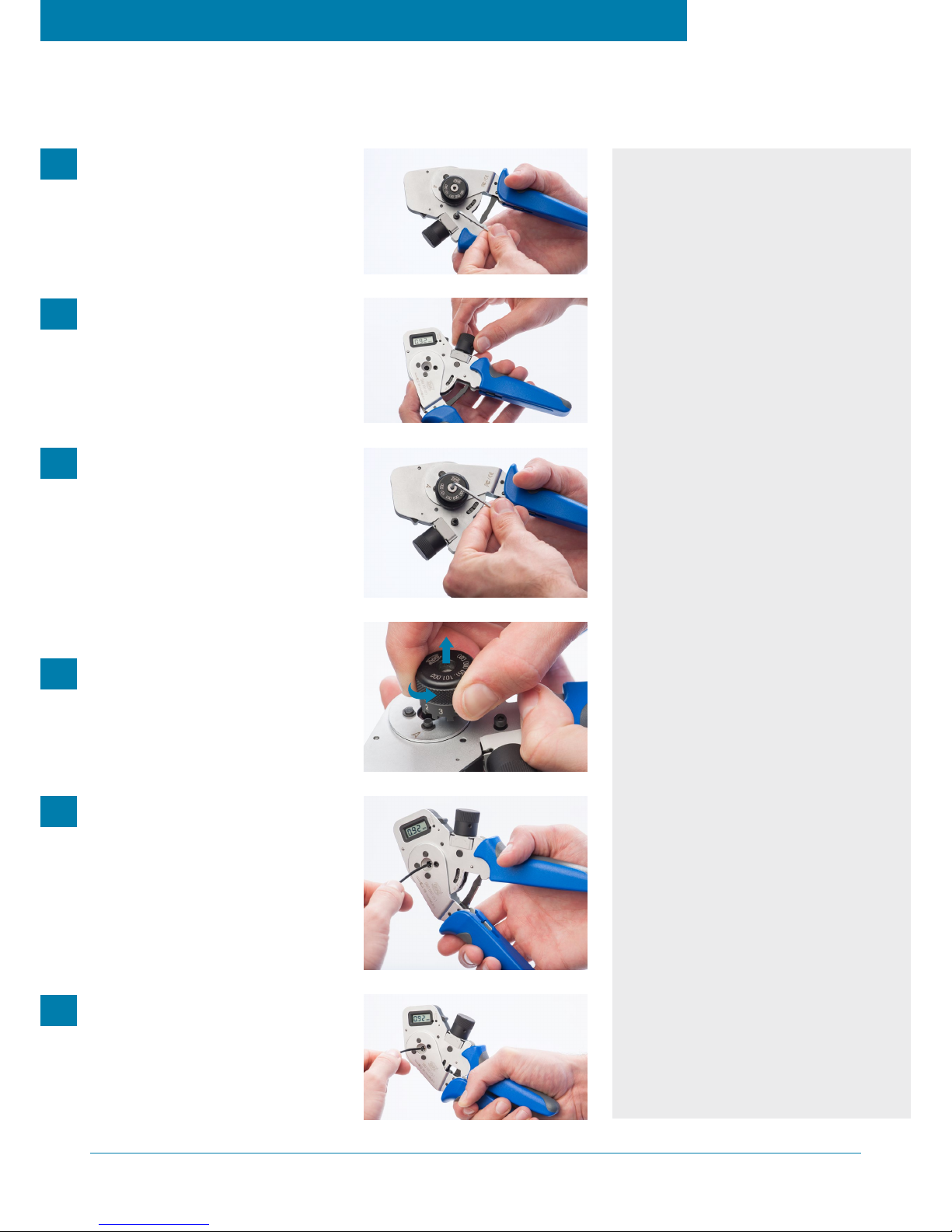
Crimpmaß mit Stellrad auf gewünschtes Maß
einstellen und anschließend Klemmschraube
wieder fixieren.
Set the crimp dimension to the desired level
with the crimp setting adjustment wheel and
then fix the clamping screw.
Crimpzange vollständig betätigen. Nach dem
Önen Kontakt entnehmen und das Ergebnis
prüfen.
Compress the crimping tool handle complete-
ly. After opening, remove the contact and
check the results.
Optional: Positionierer rückseitig auf vor-
stehende Schraube der Crimpzange setzen
und mit Innensechskantschlüssel fixieren.
Mit zweitem Schlüssel auf der Vorderseite
gegenhalten.
Optional: Place the positioner on the protrud-
ing screw, on the rear side of the crimping
tool. Secure it by using an allen key whilst
holding the screw on the front side with a
second allen key.
Optional: Zum Einstellen den Positionierer
anheben und drehen bis die gewünschte
Stellung die Markierung erreicht.
Optional: To adjust the positioner, lift and
rotate, until the required setting is aligned
with the mark.
Kontakt mit vorbereitetem Kabel in Crimp-
stelle einführen. Beachten, dass die Crimpung
mittig im Crimpbereich erfolgt (optional: Kon-
takt vollständig eingeführt in Positionierer).
Insert the contact with the prepared cable
into the crimping point. Note that the crimp-
ing is done in the middle of the crimping area
(optional: contact is fully inserted in the
positioner).
Klemmschraube zur Crimpmaßarretierung
lösen. Display über Taste „ON/OFF“ einschalten.
Loosen the clamping screw of the crimp set-
ting adjustment wheel. Switch on the display
with the “ON/OFF” button.
CRIMPVORGANG // CRIMPING PROCESS
080.000.051.000.000
„MODE“ FUNKTION
Mit der „MODE“-Taste kann die Anzeige im
Display zwischen mm, inch und MIL-Selector-
positionen umgestellt werden.
“MODE” FUNCTION
With the “MODE” button the display can be
changed between mm, inch and selector posi-
tions as given in M22520/7.
1
2
3
4
5
6
GENAUIGKEIT ÜBERPRÜFEN
Vor Arbeitsbeginn wird empfohlen, die Ein-
stellgenauigkeit zu prüfen. Die Zange dazu
vollständig schließen und in dieser Position
halten. Mit dem Stellrad das Prüfdornmaß 1,00
mm einstellen. Bei der Einstellung immer von
einem größeren Wert ausgehend beginnen.
Zange önen und erneut schließen, in dieser
Positon halten und Prüfdorn in die Crimpstelle
einführen.
Lässt sich der Prüfdorn ohne Spiel zwischen
den Crimpdornen bewegen, ist die Einstellge-
nauigkeit ausreichend. Besteht ein deutliches
Spiel muss die Zange neu kalibriert werden.
CHECK ACCURACY
Before starting work it is recommended to
check the setting accuracy. Close the tool com-
pletely and hold in this position. Adjust the val-
ue 1.00 mm with the crimp setting adjustment
wheel. Always start from a larger value when
setting. Open the tool and close again, hold in
this position and then insert the test gauge into
the crimping point.
If the test gauge can be moved between the
crimping mandrels without clearance, the
setting accuracy is sucient. If there is a clear
All dimensions are in mm. Some figures are for illustrative purposes only. Subject to change without notice.
Errors and omissions excepted. We reserve the right to change our products and their technical specifica-
tions at any time in the interest of technical improvement. This publication supersedes all prior publications.
This publication is also available as a PDF file that can be downloaded from www.odu-connectors.com.
Alle Maßangaben in mm. Die Abbildungen sind teilweise Illustrationen. Änderungen und Irrtümer vorbehal-
ten. Wir behalten uns das Recht vor, Produkte und deren technische Spezifikationen, soweit es dem tech-
nischen Fortschritt dient, jederzeit zu ändern. Mit Erscheinen dieser Publikation verlieren deren Vorgänger
ihre Gültigkeit. Diese Publikation steht auch als PDF-Datei zum Download auf www.odu.de zur Verfügung.
BEDIENUNGSANLEITUNG // INSTRUCTION MANUAL

RE-KALIBRIERUNG (REC) ZANGE
Mit der „MODE“-Taste die Anzeige auf mm umstellen und mit dem
Stellrad einen Wert größer 1,00 mm einstellen. Die Zange nun
vollständig schließen, in dieser Position halten und anschließend
den Prüfdorn in die Crimpstelle einführen. Nun das Einstellmaß
schrittweise verringern bis der Prüfdorn kein Spiel mehr auf-
weist. Die Zange kann nun wieder geönet werden.
„ON/OFF“-Taste gedrückt halten und „MODE“-Taste mit dem
Prüfdorn mindestens 5 Sekunden gleichzeitig betätigen. Die Re-
Kalibrierung ist beendet und die Anzeige springt automatisch
auf den Wert 1,00.
Verbrauchte Batterie durch gleichen Typ (CR2025) ersetzen
und auf richtige Polung achten. Vor dem Einlegen das Stellrad
auf minimalen Wert drehen (Minusrichtung). Nach Einlegen der
Batterie zeigt die Anzeige „CAL“ an. Re-Kalibrierung vornehmen.
„MODE“-Taste für mindestens 10 Sekunden gedrückt halten. Nun
werden die 8-stellige Seriennummer, die Restlebensdauer in
Prozent, ein Herstellerwert und die Anzahl der durchgeführten
Kalibrierungen angezeigt.
Fehler E1:
Vor dem Batteriewechsel wurde die Zange über das Stellrad nicht
auf den unteren Einstellwert gedreht. Siehe Abschnitt Batterie-
wechsel (CAL).
Fehler E1:
Erscheint der Fehler E1 nach korrekter Re-Kalibrierung weiterhin
im Display, ist die Verschleißgrenze des Werkzeuges erreicht.
Zange muss zur Reparatur eingesendet werden.
Fehler E2:
Re-Kalibrierung war fehlerhaft. Vorgang wiederholen.
Use the “MODE” button to change the display to mm and set a
value greater than 1.00 mm with the crimp setting adjustment
wheel. Now close the tool completely, hold in this position and
then insert the test gauge into the crimping point. Now reduce
the setting value in stages until you can move the test gauge
without play. The tool can now be opened again.
Press and hold the “ON / OFF” button and simultaneously
press the “MODE” button with the test gauge for at least 5
seconds. The re-calibration is finished and the display auto-
matically changes to the value 1.00.
Replace any used batteries with the same type (CR2025) and pay
attention to the correct polarity. Before inserting, turn the crimp
setting adjustment wheel to the minimum value (minus direction).
After inserting the battery, the display shows “CAL”. Perform a
re-calibration.
Press the “MODE” button for at least 10 seconds. Now the 8-digit
serial number, the remaining service life in percent, a manufacturer
value and the number of performed calibrations are shown.
Error E1:
Before replacing the battery, the tool was not turned to the lower
setting value via the crimp setting adjustment wheel. See battery
replacement (CAL) above.
Error E1:
If error E1 appears after correct re-calibration, the wear limit of the
tool has been reached. Tool must be sent in for repair.
Error E2:
Re-calibration was incorrect. Repeat process.
BATTERIEWECHSEL CAL
VERSCHLEISSANZEIGE
FEHLERBEHEBUNG
BATTERY REPLACEMENT CAL
WEAR MONITORING
TROUBLESHOOTING
RE-CALIBRATION (REC) TOOL
WARTUNG UND SERVICE // MAINTENANCE AND SERVICE
080.000.051.000.000
BEDIENUNGSANLEITUNG // INSTRUCTION MANUAL
Mehr Informationen auf www.odu.de
Further information at www.odu-connectors.com
[003.003.000.000.012 | 30000205]
2018/05
Table of contents
Other ODU Power Tools manuals