Taga Harmony PF-2000 User manual

PF Series [230-240V]
POWER NOISE FILTERS FOR USE
WITH AUDIO-VIDEO EQUIPMENT
Instruction Manual
Edition 05-18

2
Introduction
Thank you for purchasing this TAGA Harmony power lter.
The power lter is a perfect addition to your audio or home theatre system.
The electricity we are supplied with at our homes or workplaces is not clean and there
is almost always at least some noise.
This dirty electricity can have a negative effect on performance of your audio-video
system and even affect its life.
TAGA Harmony power lter limits noises from your electricity as well as isolates sound
and video sources from the soiled electrical network as well as indicates the correct
power phase – now your system performance will be much better!!
This instruction manual provides all of the information that you need to know about
your TAGA Harmony power lter.
Please read it carefully before you start using the unit.
Cleaning
Do not use strong or abrasive cleaners. Use a dry, soft cloth for cleaning.
Specications
Full technical specications are available on the www.TagaHarmony.com website.
Contents
Safety Instructions 3
Important Safety Instructions 4
Controls and Displays 5
Hooking Up the Filter 6
Operation 7
Specications 8
Kit Content 9

3
Safety Instructions
IMPORTANT
READ THIS SECTION CAREFULLY BEFORE PROCEEDING!
WARNING: TO REDUCE THE RISK OF FIRE OR ELECTRIC SHOCK, DO NOT EXPOSE THIS PRODUCT TO
RAIN OR MOISTURE. DO NOT REMOVE CHASSIS (OR BACK). NO USER-SERVICEABLE PARTS INSIDE.
REFER SERVICING TO QUALIFIED SERVICE PERSONNEL.
WARNING: TO REDUCE THE RISK OF FIRE OR ELECTRIC SHOCK, DO NOT
EXPOSE THIS APPARATUS TO RAIN OR MOISTURE, AND OBJECTS FILLED WITH
LIQUIDS, SUCH AS VASES, SHOULD NOT BE PLACED ON THIS APPARATUS.
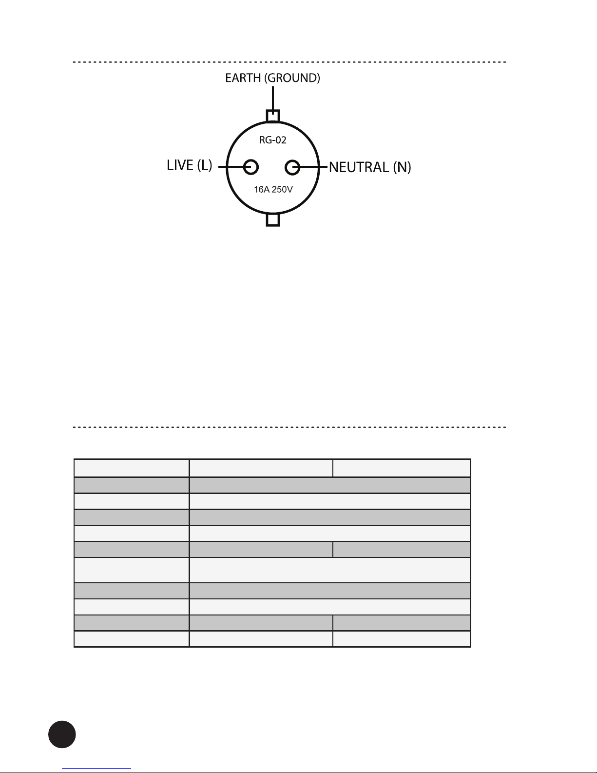
CAUTION: TO PREVENT ELECTRIC SHOCK, MATCH WIDE BLADE OF PLUG TO
WIDE SLOT, FULLY INSERT.
CAUTION: FOR CONTINUED PROTECTION AGAINST RISK OF FIRE, REPLACE
THE FUSE ONLY WITH THE SAME AMPERAGE AND VOLTAGE TYPE. REFER
REPLACEMENT TO QUALIFIED SERVICE PERSONNEL.
WARNING: UNIT MAY BECOME HOT. ALWAYS PROVIDE ADEQUATE
VENTILATION TO ALLOW FOR COOLING. DO NOT PLACE NEAR A HEAT
SOURCE, OR IN SPACES THAT CAN RESTRICT VENTILATION.
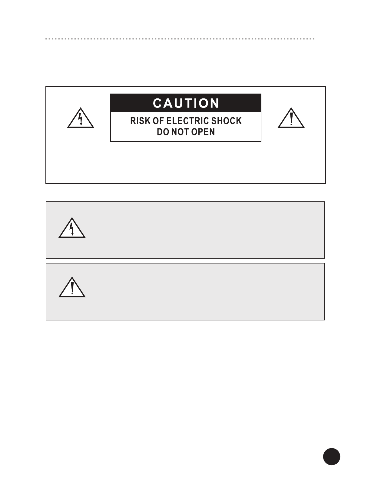
An exclamation mark in a triangle is intended to alert the user to the presence
of important operating and maintenance (servicing) instructions in the literature
accompanying the appliance.
The triangle containing a lightning symbol is intended to alert the user to the presence
of uninsulated dangerous voltages within the product’s enclosure that may be of
sucient magnitude to constitute a risk of electric shock to persons.

4
Important Safety Instructions

5
Controls and Displays
/PF-2000 model shown/
3
2
14
6
3 2 5 4 1
6 7 8
7
8
1. Power Switch (ON and OFF)
2. Power Indicator
3. Phase Indicator
4. Reset Button
5. Voltage Meter Display
6. Power Cable Input
7. Power Sockets - DIRECT Output (non-ltered)
8. Power Sockets – FILTERED Output
FLOOR MODELS
/PF-1000 model shown/
SHELF MODELS

6
1. Make sure the lter is turned off (the Power Switch is in the down OFF position and
the Power Cable is removed).
2. Using power cables (only a power cable for the lter is supplied with this product)
connect your audio-video equipment to the power sockets. Follow the below
recommendations:
FILTERED SOCKETS (these sockets are ltered. Electrical noises are ltered and
limited) – connect here your audio-video sources (CD/DVD/BluRay/Media Player,
Radio/TV Tuner, Digital-to-Analog Converter, Turntable, Preamplier, Active Speakers
etc.) and video display devices (TV Set, Video Projector etc.).
DIRECT SOCKETS (these sockets are not ltered) – connect here your amplication
audio equipment (Integrated/Power Amplier, AV/Stereo Receiver, Active Subwoofer
and similar)
Note! Check „Operation” for more information about the correct Phase when
connecting audio-video equipment.
3. Your lter is ready for operation.
Note!
We recommend to use Schuko plugs in all power cables.
Make sure not to overload the power lter. Add all amounts of power that connected
audio-video equipment consumes – the total amount should not exceed the maximum
power load which is marked on the lter and in the specications (usually 15A, 3000W).
Hooking Up the Filter
Power cable Power cable

7
Operation
Note! This unit requires a single-phase 3-conductor electrical outlet.
1. Plug the Power Cable to the lter and into the electrical outlet.
2. Turn on the lter (the Power Switch should be in the upper ON position).
The Power Indicator should light up – if not then check the connection
to the electrical outlet and whether it is powered.
3. Phase Indicator - the indicator will illuminate when the phase is incorrect.
If the Phase is incorrect perform the following steps:
a) Schuko type electrical outlet. Make sure the lter is turned off (the Power Switch is in
the down OFF position and the Power Cable is removed).
Remove the power plug from the outlet, reverse the plug by 180 degrees and put it into
the outlet.
Turn on the lter – the Phase Indicator should switch off – the Phase is correct.
b) Electrical outlet with a ground pin. Make sure the lter is turned off (the Power
Switch is in the down OFF position and the Power Cable is removed).
Contact a qualied electrician to reverse wiring connection in your electrical outlet.
Turn on the lter – the Phase Indicator should switch off – the Phase is correct.
Note! Due to risk of electric shock refer any changes related to electrical equipment to
qualied personnel.
4. The Power Sockets in your lter may have additional marking related to the female
contacts: L – LIVE | N – NEUTRAL.
If not then check the below gure showing the Power Sockets wiring (for the
correct Phase).

8
Operation
If your audio-video equipment has a phase marking for the power cable input make
sure to connect correctly the equipment power cable plug to the power lter.
5. Turn on your audio-video equipment and enjoy your system.
6. Reset – the Power Output Sockets will be powered off when the maximum power
load is exceeded (check rear of the lter or specications).
Press the RESET button to restore the power supply.
Note! When you want to turn off the power lter we recommend to turn off your
audio-video equipment rstly.
PF-2000 PF-1000
Max Spike Volt 3000V
Max Surge Current 1000A
Max Clamping Volt 470V
Noise Filter >-10dB (2-100MHz)
Sockets 2 Direct, 5 Filtered 4 Direct, 4 Filtered
Total Maximum Power Load
(for all Power Sockets) 10A, 2500W
AC Power 230V~240V 50/60Hz
Power Consumption <0.1W
Dimensions (H x W x D) 10 x 44 x 31 cm 9 x 14 x 44.5 cm
Weight (net) 5.1 kg / pc. 3.2 kg / pc.
We reserve the right to change the technical data and the design of the product without notice as a result of further development.
Specications

www.TagaHarmony.com
We strongly advise to contact a professional installer or dealer in order to install
TAGA Harmony products.
We recommend using high quality TAGA Harmony cables and other installation
accessories.
TAGA EUROPE
POLPAK POLAND Sp. z o.o.
AL.JEROZOLIMSKIE 333A
05-816 REGUŁY k/WARSZAWY, POLAND
Email: Sales@TagaHarmony.com
IMPORTANT!
Your product is marked with the symbol as showed on the left.
For EU (European Union) member users:
According to the WEEE (Waste electrical and electronic equipment)
Directive, do not dispose of this product as household waste or commercial waste.
Waste electrical and electronic equipement should be appropriately collected and
recycled as required by practices established for your country.
For information on recycling of this product, please contact your local authorities, your
household waste disposal service or the shop where you purchased the product.
Your product is marked with the symbol as showed on the left.
For EU (European Union) member users:
This product has been tested and found in compliance with
requirements of the European Community
2014/30/EU (EMC) & 2014/35/EU (LVD) directives.
Kit Content:
Power Filter 1EA
Power Cable 1EA
Instruction Manual 1EA
This manual suits for next models
2
Table of contents
Other Taga Harmony Recording Equipment manuals