Tagelus F-19T6-TAG User manual

Polyester sandfilter
top mount
INSTALLATION - BETRIEBSANLEITUNG
INSTALLATIE - INSTALACIÓN - INSTALLAZIONE
January 2005 G-TAB-000
PF 0030/15 01’05

Installation Polyester sandfilter top mount
2
The manufacturer has the right to modify the products
without previous notice for as far as their characteristics
are not really changed by this.
Technical information
Maximum working pressure
3.5 bar
Maximum working temperature
50° C
TA40
TA60
TA100
Filter area (m2)
0.17
0.29
0.45
Filter flow rate (m3/h)
8.5
14
22
Gravel 3.15-5.5 mm (kg)
15
17
50
Sand 0.4-0.8 mm (kg)
70
150
235
Filter empty weight (kg)
8.7
11.7
20
General
Check filtration kit for any evidence of damage due to
rough handling in shipment. If filtration kit is damaged
notify the carrier immediately.
Installation instructions
The pump should be placed on a flat, solid foundation,
high enough to prevent flooding of the motor.
Install the filter and pump in a sheltered location,
ensuring ventilation and adequate access for servicing.
Place the filter in its permanent location. Make sure you
can reach the valve easily. Then fix the piping. Use only
plastic piping. Size all piping adequately and keep the
number of elbows to a minimum.
Use a suction line with continuous slope.
It is essential that the suction line is free of air leaks.
The suction line should always be at least the same size
as the suction inlet of the pump.
Operation
Look inside and check lower underdrain (5) for broken
ore loose laterals (4). Fill tank for 1/3 with water. Before
filling the filter, sand guide (12) should be on the pipe
(6). Fill the filter with the specified quantity of gravel,
afterwards with sand. Remove the sand guide.
Assemble the valve (9) to the filter and tighten with the
clamp ring (10). Connect the piping. Turn the valve into
position “Rinse” and start the pump for at least 1 minute.
CAUTION:
NEVER SHIFT VALVE HANDLE POSITION WHILE
PUMP IS RUNNING.
NEVER DISASSEMBLE VALVE WHILE FILTER IS
UNDER PRESSURE.
Filtration
1. Shift valve handle to position “Filtration”
2. Start the pump
3. Note here the pressure of the pressure gauge (11)
To clean (backwash) the filter
When the pressure rises approximately 0.5 bar above the
recorded pressure it is time to backwash.
1. Shut off the pump
2. Shift the valve handle to “Backwash”
3. Start pump and let it run until water is clean (about 3
minutes).
4. Shut off the pump
5. Shift valve handle to position “Rinse” and start the
pump
6. Start pump and run for approximately one minute
7. Shut off the pump
8. Shift valve handle to position “Filtration” and start
the pump
Maintenance
The filter needs no maintenance.
Winterizing
Protect the pump, the filter and the piping from freezing.
Open the drain (2) and shift the valve handle to
“backwash”.
Replacing the sand
Open the drain (2) and let the water flow out. Remove
the sand or use the Sandvak system.
Warranty
Structural is not responsible for transport damage.
In case of damage notify carrier immediately.
Warranty period: 5 year starting from the production
date.

Polyester sandfilter top mount List of components
3
Item
Description
Qty
Part number
F-19T6-TAG
F-24T6-TAG
F-30T8-TAG
1
Tank 6” TM orient blue coated RAL 5023
3032 tank 8 ½” TM orient blue coated RAL 5023
1
1
U-19T6-TAG
U-24T6-TAG
U-30T8-TAG
2
Drain kit complete
1
G-15-4695
G-15-4695
G-15-4695
3
Black base
1
G-15-4926
G-15-4926
G-15-4596
4
Filter nozzle for filter star SS6
Filter nozzle for filter star SS8
6
8
G-30-1904
G-30-2404
G-30-3004
5
Hub for filter nozzle star SS6
Hub for filter nozzle star SS8
1
1
G-SS6-025
G-SS6-025
G-SS8-025
6
Grey PVC pipe diameter 50 x 18 mm
Grey PVC pipe diameter 63 x 19 mm
1
1
G-PVC-5018/1
0.495 m
G-PVC-5018/2
0.62 m
G-PVC-6319
0.73 m
7
O-ring 146 x 4 mm Bunan
O-ring 209.14 x 3.17 mm Bunan
1
1
G-15-4493
G-15-4493
G-15-2501
8
Adaptor 6” V-thread
Adaptor 8 ½” for 2” TM valve
1
1
G-15-5225
G-15-5225
G-15-4514
9
Black 1 ½” TM valve with 50 mm connection
Black 2” TM valve with 63 mm connection
1
1
E-27-2026ND
E-27-2026ND
E-27-2029
10
Black plastic ABS-GF clamp & screws and nuts
1
E-27-2025
E-27-2025
E-27-2028
11
Pressure gauge ¼” NPT bottom connection
1
G-15-2047
G-15-2047
G-15-2047
12
Sand guide
1
G-15-5051
G-15-5051
G-15-5051
13
O-ring EPDM 70° shore 1238 x 533 mm
O-ring NBR 165 x 5 mm 70° shore A
1
1
G-28-1008
G-28-1008
G-25-0001
14
Wrench 6” closure
1
G-15-4512
G-15-4512

Betriebsanleitung Polyester sandfilter top mount
4
Der Hersteller hat das Recht die Produkte ohne
vorangehende Benachrichtung zu ändern soweit deren
Eigen Adattatore schaften hierdurch nicht wesentlich
geändert werden.
Technische Daten
Maximaler Systemdruck
3.5 bar
Maximale Temperatur
50° C
TA40
TA60
TA100
Filterfläche (m2)
0.17
0.29
0.45
Filterleistung (m3/St)
8.5
14
22
Kies 3.15-5.5 mm (kg)
15
17
50
Sand 0.4-0.8 mm (kg)
70
150
235
Leergewicht filter (kg)
8.7
11.7
20
Allgemein
Uberprüfen Sie den Karton auf Anzeichen von Schäden,
die auf eine unsachgemässe Behandlung während des
Transports zurückzuführen sind. Benachrichtigen Sie
sofort die Transportgesellschaft, falls irgendein Teil
beschädigt ist.
Installation-Anleitungen
Die Filterinstallation sollte auf einem ebenen und festen
Fundament befestigt werden. Installieren Sie die
Filterinstallation an einem geschützten Ort und achten
Sie dabei auf eine ungehinderte Belüftung.
Bringen sie die Filtrieranlage an dem endgültigen Platz
an. Achten Sie dabei auf eine einfache Zugänglichkeit
des Ventils. Montieren Sie erst dann die Leitungen.
Am besten sollten Kunststoffleitungen benutzt werden.
Verwenden Sie Schlauchstücke mit entsprechender
Länge und entsprechendem Durchmesser und
verwenden Sie nur eine Mindestanzahl an
Winkelstücken.
Achten Sie auf eine gleichmässige Neigung des
Ansaugschlauchs. Es ist von grundlegender Wichtigkeit,
dass die Ansaugleitung frei von jeglichen Leckstellen
ist. Der Ansaugschlauch sollte mindestens den gleichen
Durchmesser wie der Ansaugstutzen der Pumpe
aufweisen.
Betrieb
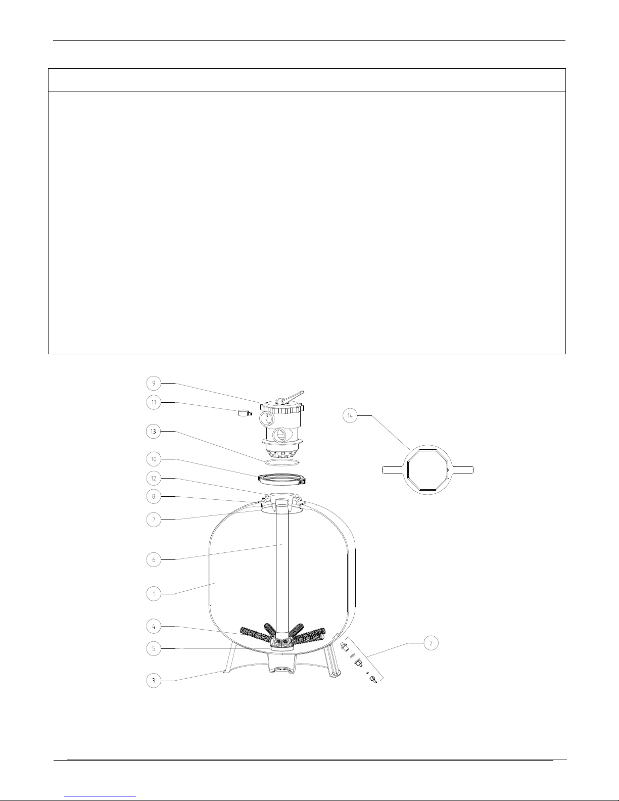
Vor Einschütten der Stoffe in den Filter kontrollieren Sie
das Innere und überprüfen Sie das niedrigliegenden
Verteilersystem (4 + 5) auf möglicherweise durch den
Transport verursachte gebrochene oder lose Filterdüsen.
Füllen Sie den Tank 1/3 mit Wasser.
Kontrollieren Sie, ob der Sandaufsatz (12) über dem
Rohr (6) sitzt.
Füllen Sie dann den Filter zunächst mit der angegebenen
Menge Kiesel, und danach mit dem Sand. Entfernen Sie
den Sandaufsatz.
Bringen Sie das Ventil (9) auf dem Filter an und
befestigen Sie dieses mit dem Klemmring (10).
Schliessen Sie die Leitungen an. Bringen Sie das Ventil
in Position “Nachspülen” und lassen Sie die Pumpe
mindestens 1 Minute lang laufen.
ACHTUNG:
NIEMALS DIE POSITION DES VENTILHEBELS
UMSTELLEN WENN DIE PUMPE LAUFT.
NIEMALS DAS VENTIL DEMONTIEREN WENN
DER FILTER UNTER DRUCK IST.
Filterbetrieb
1. Schieben Sie den Ventilhebel auf Filterstellung
2. Setzen Sie die Pumpe in Betrieb
3. Notieren Sie den Druck (11)
Reinigung (Rückspülung) des Filters
Steigt der Druck ungefähr bis 0.5 Bar über den notierten
Druckwert an, ist es Zeit zur Rückspülung.
1. Stellen Sie die Pumpe ab.
2. Schieben Sie den Ventilhebel auf “Rückspülen”
3. Setzen Sie die Pumpe in Betrieb. Die Anlage soll
rûckspulen bis das Wasser sauber erscheint (+/- drei
Minuten)
4. Stellen Sie die Pumpe ab
5. Stellen Sie den Ventilhebel auf “Nachspülen”
6. Setzen Sie die Pumpe in Betrieb und lassen Sie sie
ungefähr eine Minute laufen
7. Schalten Sie die Pumpe ab
8. Legen Sie den Ventilhebel wieder auf “Becken
filtern”und setzen Sie die Pumpe in Betrieb
Wartung
Der Filter ist für einen jahrelangen Betrieb ohne
Wartungseingriffe ausgelegt
Winterlagerung
Schützen Sie die Installation vor Frost. Drehen Sie dazu
den Ablaufkran (2) auf und bringen Sie das Ventil in die
Position “Rückspülen”.
Erzetsen des Sands
Drehen Sie den Ablaufkran (2) auf, damit das Wasser
aus dem Filter fliessen kann. Holen Sie den Sand heraus
oder benutzen Sie die Sandsabzugsvorrichtung
“Sandvak”
Garantie
Structural haftet nicht fur Transportschäden. In diesem
Fall ist unverzüglich die Transportfirma zu verstandigen
Garantieperiode : 5 Jahr ab Produktionsdatum.

Polyester sandfilter top mount Stückliste
5
P.
Kennzeichnung
M.
Teile Nr.
F-19T6-TAG
F-24T6-TAG
F-30T8-TAG
1
Tankgehause 6” TM blau RAL 5023
3032 Tankgehause 8 ½” TM blau RAL 5023
1
1
U-19T6-TAG
U-24T6-TAG
U-30T8-TAG
2
Verschluss-Satz (komplet)
1
G-15-4695
G-15-4695
G-15-4695
3
Fuss (schwarz)
1
G-15-4926
G-15-4926
G-15-4596
4
Stern-arm für Verteilersystem SS6
Stern-arm für Verteilersystem SS8
6
8
G-30-1904
G-30-2404
G-30-3004
5
Verteilkopf für Verteilersystem SS6
Verteilkopf für Verteilersystem SS8
1
1
G-SS6-025
G-SS6-025
G-SS8-025
6
PVC Rohr (grau) Durchmesser 50 x 18 mm
PVC Rohr (grau) Durchmesser 63 x 19 mm
1
1
G-PVC-5018/1
0.495 m
G-PVC-5018/2
0.62 m
G-PVC-6319
0.73 m
7
O-ring 146 x 4 mm Bunan
O-ring 209.14 x 3.17 mm Bunan
1
1
G-15-4493
G-15-4493
G-15-2501
8
Adaptor 6” V-Gewinde
Adaptor 8 ½” für 2” TM Ventil
1
1
G-15-5225
G-15-5225
G-15-4514
9
Ventil 1 ½” TM schwarz 50 mm Anschluss
Ventil 2” TM schwarz 63 mm Anschluss
1
1
E-27-2026ND
E-27-2026ND
E-27-2029
10
Klemmappe ABS-GF schwarz
1
E-27-2025
E-27-2025
E-27-2028
11
Druckmesser ¼” NPT Untenanschluss
1
G-15-2047
G-15-2047
G-15-2047
12
Sandaufsatz
1
G-15-5051
G-15-5051
G-15-5051
13
O-ring EPDM 70° shore 1238 x 533 mm
O-ring NBR 165 x 5 mm 70° shore A
1
1
G-28-1008
G-28-1008
G-25-0001
14
Schlüssel für 6” Deckel
1
G-15-4512
G-15-4512

Installation Polyester sandfilter top mount
6
Le fabricant a le droit de modifier les produits sans avis
préalable, dans la mesure où cela ne change pas
essentiellement leurs caractéristiques.
Informations techniques
Pression de fonctionnement maximum
3.5 bar
Température de fonctionnement max.
50° C
TA40
TA60
TA100
Surface filtrante (m2)
0.17
0.29
0.45
Débit de filtration (m3/h)
8.5
14
22
Gravier 3.15-5.5 mm (kg)
15
17
50
Sable 0.4-0.8 mm
70
150
235
Poids vide filtre (kg)
8.7
11.7
20
Généralités
Contrôlez le filtre à la réception pour déterminer les
pertes et dégâts dûs au transport. En cas de dégât,
avertissez immédiatement le transporteur.
Instructions de montage
Installez le filtre et la pompe dans un endroit protégé en
s’assurant que la ventilation et l’accès pour maintenance
sont appropriés. Le dispositif de filtrage doit être fixé sur
un socle plat et solide.
Installez le filtre à son emplacement définitif, en veillant
à ce que l’accès à la vanne reste aisé. Ensuite, montez
les canalisations. Il est préférable d’utiliser des
canalisations en matière synthétique. Préparez tous les
tuyaux aux bonnes dimensions et réduisez autant que
possible le nombre de coudes.
Donnez au tuyau d’aspiration une pente régulière vers la
piscine pour éliminer les poches d’air.
Il est essentiel que le tuyau d’aspiration ne présente
aucune prise d’air. Son diamètre doit touyours au moins
être égal à celui de l’orifice d’aspiration de la pompe.
Mise en service
Vérifiez que le diffuseur (5) et les crépines (4) sont en
parfait état. Remplisser la cuve 1/3 avec l’eau.
Vérifiez que le capuchon à sable (12) se trouve bien au-
dessus du tuyau (6). Remplissez le filtre de gravier et,
ensuite, de sable, dans les quantités indiquées. Retirez le
capuchon à sable.
Installez la vanne (9) sur le filtre et fixez le filtre à l’aide
de l’anneau de serrage (10). Raccordez les canalisations.
Placez la vanne en position “Rinçage canalisation”et
faites tourner la pompe pendant 1 minute au moins.
ATTENTION:
NE JAMAIS MODIFIER LA POSITION DE LA
VANNE PENDANT QUE LA POMPE FONCTIONNE.
NE JAMAIS DEMONTER LA VANNE QUAND LE
FILTRE EST SOUS PRESSION.
Filtration
1. Mettez la vanne sur le repère “Filtration”
2. Mettez la pompe en marche
3. Notez ici la pression lue au manomètre, à la
première utilisation (11)
Lavage du filtre
Dès que la pression a augmenté de 0.5 bar ou plus, vis à
vis la valeur notée, il devient nécessaire de rincer le
sable.
1. Arrêtez la pompe
2. Mettez la vanne sur le repère “lavage du filtre”
3. Remettez la pompe en marche jusqu’à ce que l’eau
devienne limpide
4. Arrêtez la pompe
5. Mettez la vanne sur le repère “rinçage canalisation”.
6. Laissez tourner la pompe pendant 1 minute
7. Arrêtez la pompe
8. Mettez la vanne sur le repère “filtration du bassin” et
remettez la pompe en marche
Maintenance
La cuve n’en nécessite aucun
Hivernage
Protégez le filtre contre le gel. A cet effet, desserrez le
robinet d’évacuation et placez la vanne en position
“Lavage du filtre”.
Remplacement du sable
Desserrez le robinet d’évacuation pour permettre à l’eau
de s’écouler du filtre. Retirez-en le sable ou utilisez
l’appareil à vide “Sandvak”.
Garantie
Tous dégâts dûs au transport ne sont pas couverts par la
garantie. Dans ce cas, des réserves doivent être faites
immédiatement au transporteur.
Période de garantie: 5 ans à partir de la date de
production.

Polyester sandfilter top mount Pièces
7
Item
Identification
Q.
Article n°
F-19T6-TAG
F-24T6-TAG
F-30T8-TAG
1
Coquille 6” TM bleue RAL 5023
Coquille 3032 8 ½” TM bleue RAL 5023
1
1
U-19T6-TAG
U-24T6-TAG
U-30T8-TAG
2
Jeu de drainage complet
1
G-15-4695
G-15-4695
G-15-4695
3
Socle (noir)
1
G-15-4926
G-15-4926
G-15-4596
4
Crépine pour système de distribution SS6
Crépine pour système de distribution SS8
6
8
G-30-1904
G-30-2404
G-30-3004
5
Tête de distribution SS6
Tête de distribution SS8
1
1
G-SS6-025
G-SS6-025
G-SS8-025
6
Tube grise PVC diamètre 50 x 18 mm
Tube grise PVC diamètre 63 x 19 mm
1
1
G-PVC-5018/1
0.495 m
G-PVC-5018/2
0.62 m
G-PVC-6319
0.73 m
7
Joint 146 x 4 mm Bunan
Joint 209.14 x 3.17 mm Bunan
1
1
G-15-4493
G-15-4493
G-15-2501
8
Adaptateur 6”
Adaptateur 8 ½” pour vanne 2” TM
1
1
G-15-5225
G-15-5225
G-15-4514
9
Vanne 1 ½” TM noire connection 50 mm
Vanne 2” TM noire connection 63 mm
1
1
E-27-2026ND
E-27-2026ND
E-27-2029
10
Collier ABS-GF noire
1
E-27-2025
E-27-2025
E-27-2028
11
Manomètre ¼” NPT montage inférieur
1
G-15-2047
G-15-2047
G-15-2047
12
Capuchon à sable
1
G-15-5051
G-15-5051
G-15-5051
13
O-ring EPDM 70° shore 1238 x 533 mm
O-ring NBR 165 x 5 mm 70° shore A
1
1
G-28-1008
G-28-1008
G-25-0001
14
Clé pour couvercle 6”
1
G-15-4512
G-15-4512

Installatie Polyester sandfilter top mount
8
De fabrikant heeft het recht om de producten te wijzigen
zonder voorafgaande melding, voor zover hun
eigenschappen hierdoor niet wezenlijk veranderd
worden.
Technische gegevens
Maximale werkdruk
3.5 bar
Maximale werkdruktemperatuur
50° C
TA40
TA60
TA100
Filteroppervlakte (m2)
0.17
0.29
0.45
Filterdebiet (m3/h)
8.5
14
22
Kiezel 3.15-5.5 mm (kg)
15
17
50
Zand 0.4-0.8 mm
70
150
235
Gewicht van de filter (kg)
8.7
11.7
20
Algemeen
Kontroleer bij ontvangst de filter op eventuele
transportschade en verwittig de transporteur
onmiddellijk bij beschadiging.
Installatie
Plaats de filter op een vlakke en gemakkelijk te bereiken
plaats. Om beschadiging van de volledige unit te
voorkomen is het aan te raden het lokaal te ventileren en
droog te houden.
Plaats de filter op de definitieve plaats. Houd rekening
met een gemakkelijke bereikbaarheid van de klep.
Monteer dan pas de leidingen. Bij voorkeur worden
kunststofleidingen gebruikt. Dimensioneer alle leidingen
correct en beperk het aantal bochten tot een minimum.
Plaats de aanzuigleiding onder lichte helling om
luchtbellen te vermijden. Het is belangrijk dat de
aanzuigleiding vrij is van luchtlekken. De diameter van
de aanzuigleiding moet altijd minstens even groot zijn
als de aanzuigopening van de pomp.
In werking stelling
Controleer of de verdeelkop (5) en de verdeelbuizen (4)
in goede staat zijn. Vul de filter voor één derde met
water. Controleer of de vultrechter (12) op de pijp (6 )
zit. Vul dan de filter eerst met de aangegeven
hoeveelheid kiezel, daarna met het zand. Verwijder de
vultrechter.
Plaats het ventiel (9) op de filter en maak het vast met de
klemring (10). Sluit de leidingen aan. Plaats het ventiel
in de stand “Naspoelen” en laat de pomp minstens 1
minuut draaien.
OPGELET:
NOOIT DE POSITIE VAN HET VENTIEL
VERANDEREN TERWIJL DE POMP DRAAIT.
NOOIT HET VENTIEL DEMONTEREN ALS DE
FILTER NOG ONDER DRUK STAAT.
Filtratie
1. Plaats het ventiel in de positie “Filtratie”
2. Laat de pomp draaien
3. Noteer de druk afgelezen op de manometer (11)
Terugspoelen van de filter
Zodra de druk 0.5 bar gestegen is (t.o.v. de onder
filtratie genoteerde waarde), is het noodzakelijk het
filterzand te spoelen. Hierbij gaat men als volgt te werk:
1. Zet de pomp af.
2. Plaats het ventiel in de positie “Spoelen van filter”.
3. Laat de pomp weer draaien net zolang tot het water
helder is (ca. 3 minuten).
4. Zet de pomp terug af.
5. Plaats het ventiel in de positie “Naspoelen”.
6. Laat de pomp gedurende 1 minuut draaien.
7. Zet de pomp af.
8. Plaats het ventiel in de positie “Filtratie” en zet de
pomp weer aan.
Onderhoud
De filter zelf heeft geen onderhoud nodig.
Overwinteren
Het water moet uit de filter, de pomp en de leidingen
worden verwijderd om deze te beschermen tegen vorst.
Draai hiervoor het aflaatkraantje (2) los en plaats het
ventiel in de stand “Spoelen van de filter”.
Vervangen van het zand
Draai hiervoor het aflaatkraantje (2) los om het water uit
de filter te laten. Schep het zand er uit of gebruik het
Sandvak vacuüm apparaat.
Waarborg
De leverancier is niet verantwoordelijk voor
transportschade. In geval van schade onmiddellijk het
transportbedrijf verwittigen.
Waarborgperiode: 5 jaar vanaf de produktiedatum.

Polyester sandfilter top mount Stuklijst
9
Item
Omschrijving
Q.
Stuknummer
F-19T6-TAG
F-24T6-TAG
F-30T8-TAG
1
Tank 6” TM blauw RAL 5023
Tank 3032 8 ½” TM blauw RAL 5023
1
1
U-19T6-TAG
U-24T6-TAG
U-30T8-TAG
2
Volledige draineerkit
1
G-15-4695
G-15-4695
G-15-4695
3
Tankvoet (zwart)
1
G-15-4926
G-15-4926
G-15-4596
4
Lateral van verdeelsysteem SS6
Lateral van verdeelsysteem SS8
6
8
G-30-1904
G-30-2404
G-30-3004
5
Verdeelkop voor verdeelsysteem SS6
Verdeelkop voor verdeelsysteem SS8
1
1
G-SS6-025
G-SS6-025
G-SS8-025
6
PVC buis (grijs) diameter 50 x 18 mm
PVC buis (grijs) diameter 63 x 19 mm
1
1
G-PVC-5018/1
0.495 m
G-PVC-5018/2
0.62 m
G-PVC-6319
0.73 m
7
O-ring 146 x 4 mm Bunan
O-ring 209.14 x 3.17 mm Bunan
1
1
G-15-4493
G-15-4493
G-15-2501
8
Adaptor 6”V-draad
Adaptor 8 ½” voor 2” TM klep
1
1
G-15-5225
G-15-5225
G-15-4514
9
Klep 1 ½” TM zwart met aansluiting 50 mm
Klep 2” TM zwart met aansluiting 63 mm
1
1
E-27-2026ND
E-27-2026ND
E-27-2029
10
Klemband ABS-GF zwart
1
E-27-2025
E-27-2025
E-27-2028
11
Manometer ¼” NPT onderaansluiting
1
G-15-2047
G-15-2047
G-15-2047
12
Vultrechter
1
G-15-5051
G-15-5051
G-15-5051
13
O-ring EPDM 70° shore 1238 x 533 mm
O-ring NBR 165 x 5 mm 70° shore A
1
1
G-28-1008
G-28-1008
G-25-0001
14
Sleutel 6” deksel
1
G-15-4512
G-15-4512

Instalación Polyester sandfilter top mount
10
El fabricante tiene el derecho de modificar los productos
sin previo aviso, mientras no cambien realmente sus
características.
Información técnica
Presión máxima de trabajo
3.5 bar
Temperatura máxima de trabajo
50° C
TA40
TA60
TA100
Superficie de filtración (m2)
0.17
0.29
0.45
Caudal de filtro (m3/h)
8.5
14
22
Grava 3.15-5.5 mm (kg)
15
17
50
Arena 0.4-0.8 mm
70
150
235
Filtro peso (kg)
8.7
11.7
20
Principios generales
Al recibir el filtro, asegúrese de que no ha sufrido daños
en el transporte. Communique de inmediato cualquier
daño al transportista.
Instrucciones de instalación
Asegure el filtro a una obra de fundación plana y firme.
Instale el filtro y la bomba en un lugar protegido, con
buena ventilación y fácil acceso para mantenimiento.
Coloque el filtro en el lugar donde ha de quedar
(asegúrese de que puede alcanzar fácilmente de llava) y
coloque las tuberías. Es preferible utilizar tuberías de
material plástico.
Utilizar los tubos del diámetro apropiado, de un mínimo
de codos.
Tienda los conductos de aspiración con una ligera
inclinación para evitar la formación de burbujas.
La línea de aspiración no ha de tener ninguna entrada de
aire. Utilizar en esta línea un conducto por lo menos del
tamaño de la boca de aspiración de la bomba.
Funcionamiento
Asegúrese de que el difusor (5) y los tubos repartidores
(4) están en perfectas condiciones. Llena una tercera
parte del filtro con agua.
Compruebe si la caperuza de arena (12) se posiciona
correctamente sobre el tubo (6). Llena ahora el filtro con
la cantidad de silicio indicada y luego con arena.
Retire la caperuza de arena. Coloque la válvula (9) sobre
el filtro y cierre la válvula con la brida (10). Connecte
los conductos.
Ponga la vávula en “lavado contracorriente” y haga
funcionar la bomba durante 1 minuto.
ATENCIÓN:
NUNCA MODIFIQUE LA POSICIÓN DE LA
VÁLVULA CUANDO LA BOMBA ESTE EN
FUNCIONAMIENTO.
NUNCA DESMONTE LA VÁLVULA CUANDO EL
FILTRO ESTE A PRESIÓN.
Filtración
1. Posicionar la válvula en “Filtración”
2. Poner la bomba en marcha.
3. Anotar aquí la presión que indica el manómetro .
Lavado del filtro
Cuando la presión anotada se aumentó, hay que lavar la
arena..
1. Apague la bomba.
2. Ponga la válvula en “lavado contracorriente”.
3. Haga funcionar la bomba hasta que el agua salga
clara (durante +/- 3 minutos).
4. Pare la bomba.
5. Ponga la válvula en “Aclarado”.
6. Haga funcionar la bomba durante 1 minuto.
7. Pare la bomba.
8. Ponga la válvula en la posición “Filtración” y ponga
la bomba en marcha.
Mantenimiento
El filtro no necesita mantenimiento.
Protección durante el invierno
Proteja el sistema de filtración contra las heladas.
Quite los tapones y deje escapar todo el líquido de la
bomba y de los conductos.
El grifo de descarga (2) debe estar abierto y la válvula
en la posición “lavado contracorriente”.
Para reemplazar la arena
Desmonte el grifo de descargo (2) para dar salida al agua
del filtro. Tire la arena o utilice la aspiradora de arena
“Sandvak” para vaciarlo.
Garantía
El proveedor no es responsable de los daños causados en
el transporte. Advertir inmediatemente al transportista si
el material llega deteriorado.
Periodo de garantía: 5 años desde la fecha de
producción.

Polyester sandfilter top mount Relación de piezas
11
No.
Descripción
C.
Artículo
F-19T6-TAG
F-24T6-TAG
F-30T8-TAG
1
Filtro 6” TM azul RAL 5023
Filtro 3032 8 ½” TM azul RAL 5023
1
1
U-19T6-TAG
U-24T6-TAG
U-30T8-TAG
2
Juego de vaciado completo
1
G-15-4695
G-15-4695
G-15-4695
3
Soporte (negro)
1
G-15-4926
G-15-4926
G-15-4596
4
Tubo repartidor SS6
Tubo repartidor SS8
6
8
G-30-1904
G-30-2404
G-30-3004
5
Difusor SS6
Difusor SS8
1
1
G-SS6-025
G-SS6-025
G-SS8-025
6
Tubo diámetro (gris) 50 x 18 mm
Tubo diámetro (gris) 63 x 19 mm
1
1
G-PVC-5018/1
0.495 m
G-PVC-5018/2
0.62 m
G-PVC-6319
0.73 m
7
Junta tórica 146 x 4 mm Bunan
Junta tórica 209.14 x 3.17 mm Bunan
1
1
G-15-4493
G-15-4493
G-15-2501
8
Adaptator 6”
Adaptator 8 ½”
1
1
G-15-5225
G-15-5225
G-15-4514
9
Válvula 1 ½” TM negro con conexión 50 mm
Válvula 2” TM negro con conexión 63 mm
1
1
E-27-2026ND
E-27-2026ND
E-27-2029
10
Collar negro ABS-GF
1
E-27-2025
E-27-2025
E-27-2028
11
Manometro ¼” NPT juntar a bajo
1
G-15-2047
G-15-2047
G-15-2047
12
Caperuza de arena
1
G-15-5051
G-15-5051
G-15-5051
13
Junta tórica EPDM 70° shore 1238 x 533 mm
Junta tórica NBR 165 x 5 mm 70° shore A
1
1
G-28-1008
G-28-1008
G-25-0001
14
Llava para la tapa
1
G-15-4512
G-15-4512

Installazione Polyester sandfilter top mount
12
Il fabbricante ha il diritto di modificare i prodotti senza
previo avviso a patto che le loro caratteristiche non
vengano cambiate sostanzialmente.
Dati tecnici
Pressione massima di esercizio
3.5 bar
Temperatura massima
50° C
TA40
TA60
TA100
Superficie filtrante (m2)
0.17
0.29
0.45
Velocità de filtrazione (m3/h)
8.5
14
22
Ghiaia 3.15-5.5 mm (kg)
15
17
50
Sabbia 0.4-0.8 mm
70
150
235
Péso filtro (kg)
8.7
11.7
20
Generalita
Controllare el filtro al momento del ricevimento per
verificare eventuali perdite e danni dovuti al trasporto .
Istruzioni per l’installazione
El filtro deve essere montata su un basamento piatto e
robusto. Installare el filtro in un luogo protetto e ben
ventilato.
Mettere l’impianto nella collocazione definitiva.
Assicurarsi che la valvola sia raggiungibile facilamente.
Poi montare le tubature. Preferibilmente utilizzare
tubature in plasica.
Determinare l’esatta misura di tutte le tubazioni e ridurre
al minimo il numero di gomite e curve.
É importante che il tubo di aspirazione non presenti
perdite d’aria. Il diametro del tubo di aspirazione deve
essere almeno uguale all’apertura della pompa.
Funzionamento
Verificare che la stella degli (5) otto ripartitori inferiori
(4) sia in perfetto stato. Riempire per uno terzo il corpo
filtro con acqua.
Controllare che il coperchio (12) si trovi sul tubo (6).
Riempire il filtro prima con la quantità indicate di
ghiaia, poi con la sabbia. Eliminare il coperchio (12).
Collocare la valvola (9) sul filtro sul filtro e fissaria con
il fermo (10). Allaciare le tubature.
Collocare la valvola in posizione “Risciacquo” e far
girare la pompa per almeno 1 minuto.
ATTENZIONE:
NON SPOSTARE MAI LA MANIGLIA DELLA
VALVOLA MENTRE LA POMPE E’IN FUNZIONE.
NON SMONTARE MAI LA VALVOLA MENTRE IL
FILTRO E’ANCORA IN PRESSIONE.
Filtrazione
1. Mettere la valvola in posizione “Filtrazione”.
2. Accendere la pompa.
3. Prendere nota della pressione sul manometro.
Pulizia del filtro
Quando la pressione è aumentata di 0.5 o piu bar,
rispetto al valore indicato.
1. Spegnere la pompa.
2. Mettere la valvola in posizione “Contralavaggio”.
3. Accendere la pompa per 3 min.
4. Spegnere la pompa.
5. Mettere la valvola in posizione “Risciacquo”.
6. Accendere la pompa per 1 min.
7. Spegnere la pompa.
8. Mettere la valvola in posizione “Filtrazione” e
accendere la pompa.
Manutenzione
Il filtro non necessita di alcuna manutenzione.
Periodo ivernale
Proteggere l’impianto filtrante dal gelo. A questo scopo
svitare il rubinetto (2) e collocare la valvola in posizione
“Contralavaggio. Rimuovere tutti I tappi e svuotare la
pompa e tutte le tubazioni.
Sostituzione della sabbia
Svitare il rubinetto per far uscire l’acqua dal filtro.
Togliere la sabbia oppure utilizzare l’aspiratore di sabbia
per vuatario “sandvak”.
Garanzia
I danni dovuti al trasporto non sono coperti dalla
garanzia fornitori. In caso di danneggiamenti, avvertire
immediatemente il trasportatore.
Periodo di garanzia: 5 anni dalla data di produzione.

Polyester sandfilter top mount Elenco dei componenti
13
P.
Descrizione
Q.
Numero
F-19T6-TAG
F-24T6-TAG
F-30T8-TAG
1
Filtro 6” TM azzurro RAL 5023
Filtro 3032 8 ½” TM azzurro RAL 5023
1
1
U-19T6-TAG
U-24T6-TAG
U-30T8-TAG
2
Robinetto completo
1
G-15-4695
G-15-4695
G-15-4695
3
Basamento (nero)
1
G-15-4926
G-15-4926
G-15-4596
4
Candelette SS6
Candelette SS8
6
8
G-30-1904
G-30-2404
G-30-3004
5
Diffusore SS6
Diffusore SS8
1
1
G-SS6-025
G-SS6-025
G-SS8-025
6
Tronchetto in PVC 50 x 18 mm
Tronchetto in PVC 63 x 19 mm
1
1
G-PVC-5018/1
0.495 m
G-PVC-5018/2
0.62 m
G-PVC-6319
0.73 m
7
O-ring 146 x 4 mm Bunan
O-ring 209.14 x 3.17 mm Bunan
1
1
G-15-4493
G-15-4493
G-15-2501
8
Adattatore 6”
Adattatore 8 ½”
1
1
G-15-5225
G-15-5225
G-15-4514
9
Valvola 1 ½” TM nero conn. 50 mm
Valvula 2” TM negro conn. 63 mm
1
1
E-27-2026ND
E-27-2026ND
E-27-2029
10
Collare nero ABS-GF
1
E-27-2025
E-27-2025
E-27-2028
11
Manometro ¼” NPT
1
G-15-2047
G-15-2047
G-15-2047
12
Coperchio
1
G-15-5051
G-15-5051
G-15-5051
13
O-ring EPDM 70° shore 1238 x 533 mm
O-ring NBR 165 x 5 mm 70° shore A
1
1
G-28-1008
G-28-1008
G-25-0001
14
Chiave del coperchio 6”
1
G-15-4512
G-15-4512

Dimensions Polyester sandfilter top mount
14

BE.412.732.822
This manual suits for next models
2
Table of contents
Languages:
Popular Water Filtration System manuals by other brands

Cuno
Cuno CFS717 Installation & operating instructions

Honeywell
Honeywell F74C Series installation instructions

Pentair
Pentair AQUATIC ECO-SYSTEMS ARIAS 6000 Installation and user guide

Wood master
Wood master COMMERCIAL Series manual

BWT
BWT Infinity A Installation and operating manual

Master Water Conditioning
Master Water Conditioning PURO PRO 1800 SC Series Operation manual

Pentair
Pentair EVERPURE ActivTapp ACS-1 Installation and operation guide

Asutec
Asutec ASMS-10-EW-08 operating manual

UV Dynamics
UV Dynamics UVD320E Installation and maintenance manual

Dometic
Dometic RO400 Service manual

Sera
Sera F 400 INFORMATION FOR USE

CSI
CSI signature 2 SK15 Installation and operation manual