TAJIMA TFHX Series User manual

TEHX-C &
TFHX SERIES
USER’S MANUAL
TEHX-C &
TFHX SERIES
M-EFHX07-E
(2004 .01)

FOREWORD
This manual is a guidebook for using TAJIMA automatic embroidery machines TFHX series and TEHX-C (referred to as machine
hereafter) correctly. Please read this manual thoroughly, understand the contents, and then use the machine.
This manual is composed of the following contents.
[IMPORTANT WARNING ITEMS FOR SAFE OPERATION]
[OUTLINE OF THE MACHINE
[BASIC OPERATION]
[DESIGN DATA]
[OPERATION OF MACHINE]
[SETTING FOR MACHINE]
[SETTING FOR EMBROIDERY]
[OPTION]
[OUTLINE OF FUNCTIONS]
[TROUBLESHOOTING AND MAINTENANCE]
[APPENDIX]
Concerning optional devices, please refer to the instruction manual of the optional device you have purchased.
The contents of this manual may contain discrepancies in detailed information when compared with the actual product you have
bought due to difference of target model or continued research and improvements.If any question about the products or contents of
this manual arises, please consult your TAJIMA distributor.
Please keep this manual with care near the machine for quick reference.
Tokai Industrial Sewing Machine Co., Ltd.
IMPORTANT SAFETY INSTRUCTIONS
Operation of the machine requires correct operation. Items that require your special attention on operation are specified below with
the warning symbol and signal word. These items must be strictly observed to ensure safety. Signal word definition is given below.
*1:A condition caused by electric shock, injury, fracture of a bone, etc., that leads to aftereffects, or an injury that necessi-
tates hospitalization or visits to a hospital over a long period.
*2: An injury that does not necessitate hospitalization or visit to a hospital over a long period.
: Prohibited items
: Items that may cause electric shock if not observed
: Items that must be followed carefully to ensure safe operation
DANGER
Indicates that there is a lot of danger of death or serious injuries (*1) if the instructions is not
observed.
WARNING
Indicates that there is a likelihood of death or serious injuries (*1) if the instruction is not
observed.
CAUTION
Indicates a potentially hazardous situation which, if not avoided, may result in minor or
moderate injury (*2) or property damage.
GC06
!
!
!

CONTENTS
IMPORTANT WARNING ITEMS FOR SAFE OPERATION
INSTALLATION ENVIRONMENT ...................................................................................................... 1
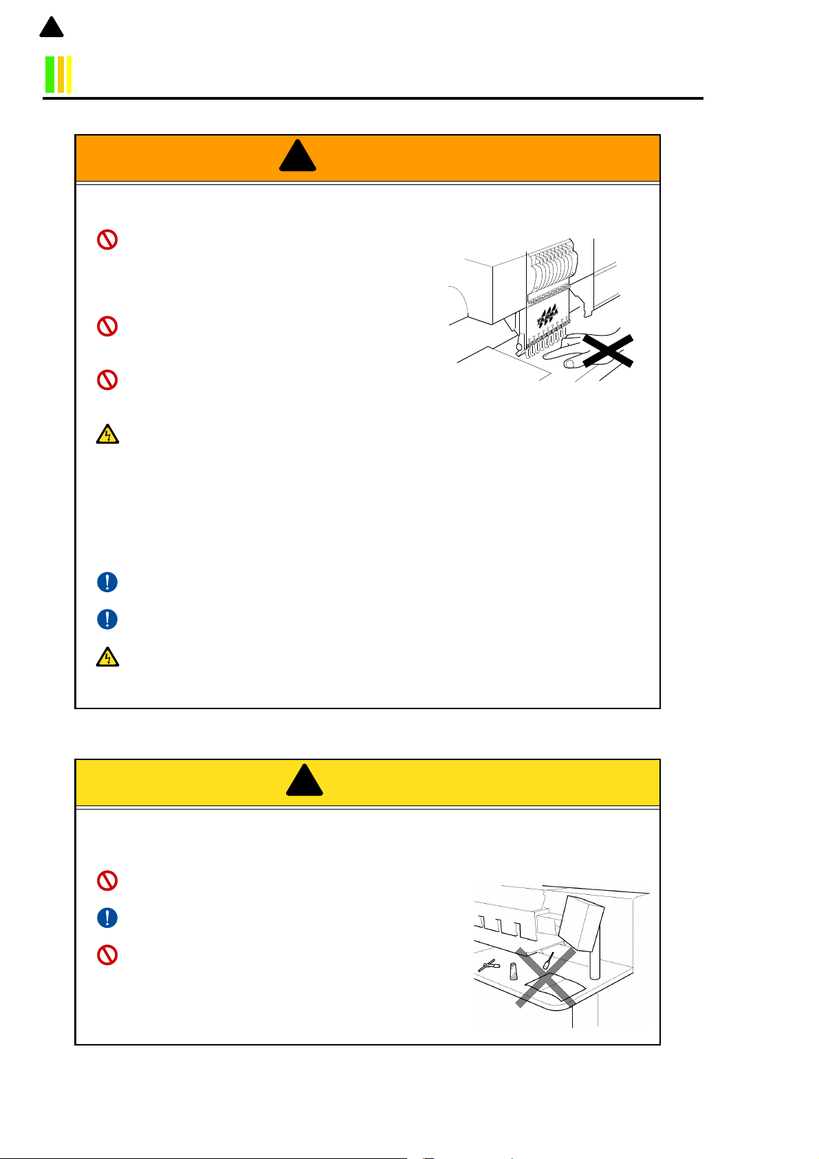
CAUTIONS ON MACHINE OPERATION........................................................................................... 2
WARNING LABELS ........................................................................................................................... 4
IMPORTANT DIRECTIVE ITEMS............................................................................................................. 4
APPLYING POSITION OF WARNING LABELS...................................................................................... 4
CHAPTER 1 OUTLINE OF THE MACHINE
MAIN FUNCTIONS ......................................................................................................................... 1-1
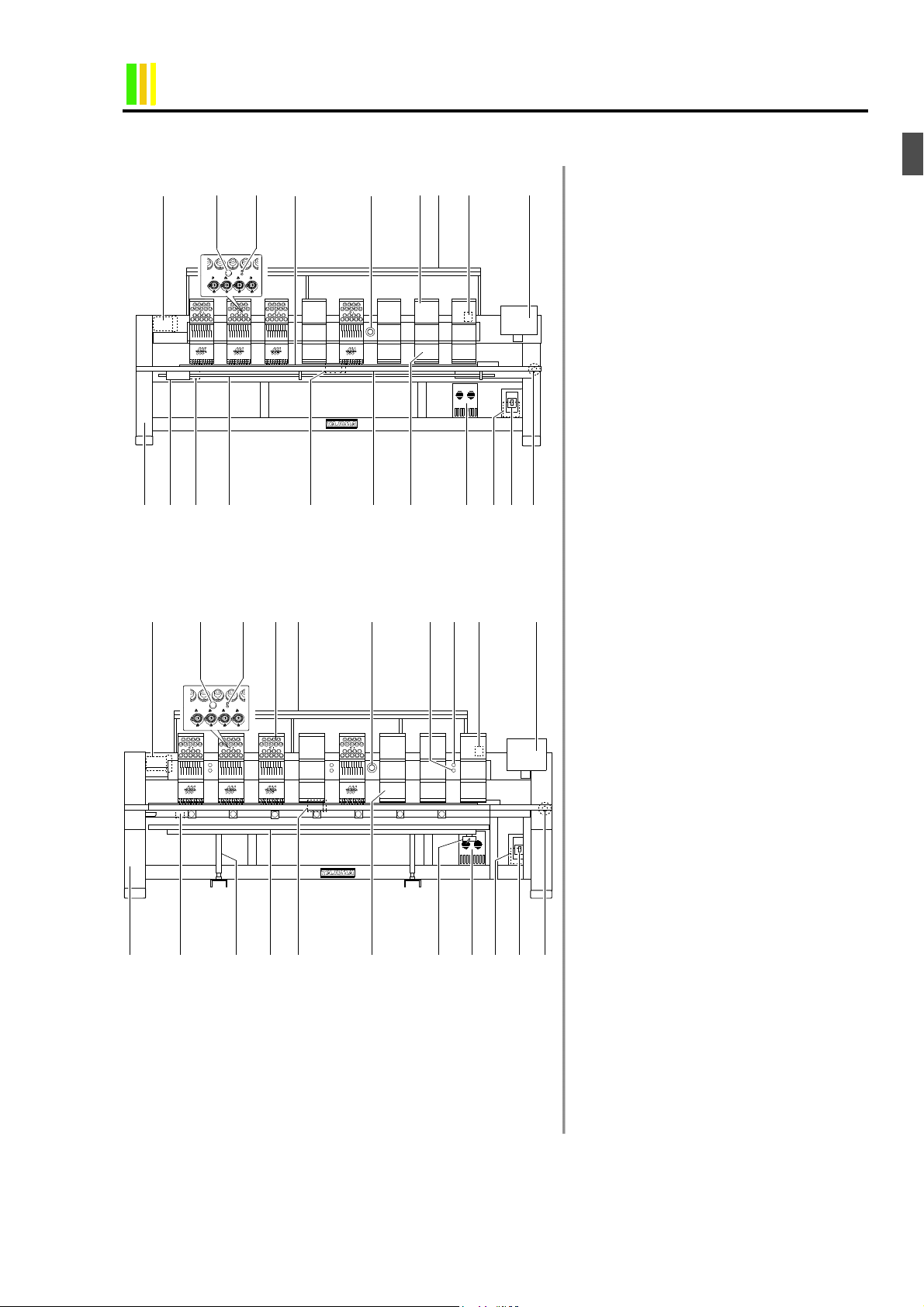
TFHX SERIES NAME OF EACH PART.......................................................................................... 1-2
NAME OF EACH PART OF TEHX-C .............................................................................................. 1-4
POWER SUPPLY SPECIFICATION, POWER SUPPLY/DRIVER BOX ......................................... 1-5
SWITCHING OF POWER SUPPLY SPECIFICATION (100/200 V)................................................ 1-6
OPERATION PANEL ...................................................................................................................... 1-7
FUNCTION OF EACH PART...................................................................................................................1-7
COMMUNICATION SPEED OF SERIAL I/F CONNECTOR ................................................................1-8
EACH SETTING KEY...................................................................................................................... 1-9
FUNCTION OF EACH SETTING KEY ...................................................................................................1-9
ROTARY-TYPE TENSION BASE ................................................................................................. 1-12
FUNCTION OF TENSION BASE SWITCH ..........................................................................................1-12
FUNCTION OF THREAD BREAKAGE INDICATOR LAMP.............................................................1-12
NEEDLE BAR SUSPENSION LEVER .......................................................................................... 1-13
CHAPTER 2 OPERATION BASICS
POWER SWITCH AND EMERGENCY STOP SWITCH................................................................. 2-1
POWER SWITCH ......................................................................................................................................2-1
EMERGENCY STOP SWITCH ................................................................................................................2-1
START AND STOP ......................................................................................................................... 2-2
OPERATION BY BAR SWITCH (TFHX) ...............................................................................................2-2
OPERATION BY START/STOP SWITCH (EXCLUDING TFHX)........................................................2-3
STOP BY PRESET HALT (P.6-27)...........................................................................................................2-3
FLOPPY DISK AND FLOPPY DISK DRIVE.................................................................................... 2-4
FLOPPY DISK ...........................................................................................................................................2-4
FLOPPY DISK DRIVE (FDD) ..................................................................................................................2-4
INSTALLATION OF SOFTWARE ................................................................................................... 2-5
DISPLAY OF DISPLAY AREA ...................................................................................................... 2-10
DISPLAY AFTER TURNING ON THE POWER ..................................................................................2-10
USUAL DISPLAY ...................................................................................................................................2-10
DISPLAY DURING OPERATION .........................................................................................................2-10
INSPECTIONS BEFORE STARTING OPERATION..................................................................... 2-11
BASIC OPERATION PROCEDURE ............................................................................................. 2-12
CHAPTER 3 DESIGN DATA
DESIGN DATA INPUT (MEMORY)................................................................................................. 3-1
DESIGN DATA INPUT (FLOPPY DISK) ......................................................................................... 3-2
DESIGN DATA INPUT (EXTERNAL DEVICE)................................................................................ 3-4
STANDBY INPUT............................................................................................................................ 3-6
MEMORY DELETION ..................................................................................................................... 3-8
STITCH DATA EDIT (MODIFY) .................................................................................................... 3-10
STITCH DATA EDIT (INSERT) ..................................................................................................... 3-14
STITCH DATA EDIT (DELETE) .................................................................................................... 3-18
STITCH DATA EDIT (CLEANUP) ................................................................................................. 3-21
FLOPPY DISK (DESIGN DATA WRITING)................................................................................... 3-23
FLOPPY DISK (DESIGN DATA DELETING) ................................................................................ 3-27
FLOPPY DISK (FORMATTING).................................................................................................... 3-29
CHAPTER 4 OPERATION OF THE MACHINE
MANUAL COLOR CHANGE ........................................................................................................... 4-1
MANUAL THREAD TRIMMING....................................................................................................... 4-2
MANUAL ORIGIN RETURN............................................................................................................4-3
MANUAL OFFSET .......................................................................................................................... 4-4
TRACE ............................................................................................................................................ 4-5
MANUAL FRAME TRAVEL.............................................................................................................4-6
FRAME BACK/FORWARD ............................................................................................................. 4-8
FRAME ORIGIN MEMORY (TFHXII, TFHX-IIC).......................................................................... 4-10
FRAME ORIGIN MEMORY (TFHX, TFHX-C, TEHX-C)................................................................ 4-12
POWER RESUME (TFHXII, TFHX-IIC)......................................................................................... 4-13
POWER RESUME (TFHX, TFHX-C, TEHX-C) ............................................................................. 4-15
STITCH COUNTER/DESIGN TIME .............................................................................................. 4-16
CONFIRMATION MODE...............................................................................................................4-17
GC06

Chapter 1
Chapter 2
Chapter 3
Chapter 4
Chapter 5
Chapter 6
Chapter 7
Chapter 8
Chapter 9
CONFIRMATION OF THE NUMBER OF STITCHES UP TO AUTOMATIC LUBRICATION........ 4-19
MANUAL LUBRICATION ..............................................................................................................4-20
TABLE UP/DOWN......................................................................................................................... 4-21
SEQUIN DEVICE UP/DOWN........................................................................................................ 4-22
CHAPTER 5 SETTING FOR THE MACHINE
MAX REVOLUTION ........................................................................................................................ 5-1
LOW SPEED R.P.M. ....................................................................................................................... 5-2
LIMIT OF MAX REVOLUTION ........................................................................................................ 5-3
THE NUMBER OF INCHING TIMES AT START ............................................................................ 5-4
FRAME DRIVE START TIMING ..................................................................................................... 5-5
FRAME TRAVEL SPEED................................................................................................................ 5-6
ADJUSTMENT OF STOP POSITION OF MAIN SHAFT................................................................. 5-7
FRAME DRIVE METHOD ............................................................................................................... 5-8
FRAME BACK/FORWARD ............................................................................................................. 5-9
TABLE UP/DOWN DEVICE .......................................................................................................... 5-11
CHAPTER 6 SETTING FOR EMBROIDERY
UPPER THREAD BREAKAGE DETECTION.................................................................................. 6-1
UNDER THREAD BREAKAGE DETECTION (DETECTING TIMES) ............................................. 6-4
UNDER THREAD BREAKAGE DETECTION (MOVEMENT RATIO) ............................................. 6-7
AUTOMATIC THREAD TRIMMING (ATH).................................................................................... 6-10
AUTOMATIC COLOR CHANGE/AUTOMATIC START ................................................................ 6-13
NEEDLE BAR SELECTION .......................................................................................................... 6-15
REPEAT ........................................................................................................................................ 6-19
AUTOMATIC OFFSET .................................................................................................................. 6-22
OFFSETTING AT AUTOMATIC COLOR CHANGE...................................................................... 6-24
AUTOMATIC START AFTER AUTOMATIC DATA SET............................................................... 6-25
AUTOMATIC ORIGIN RETURN.................................................................................................... 6-26
PRESET HALT.............................................................................................................................. 6-27
STOP AT LOWER D. POINT (PSEUDO-FIXED POSITION)........................................................ 6-29
DATA CONVERSION.................................................................................................................... 6-30
JUMP CONVERSION ................................................................................................................... 6-32
AUTOMATIC JUMP ...................................................................................................................... 6-33
SATIN STITCH.............................................................................................................................. 6-34
BACKLASH ................................................................................................................................... 6-35
ALL HEAD SEWING AFTER FRAME BACK ................................................................................ 6-36
CHAPTER 7 OPTION
BORING DEVICE............................................................................................................................ 7-1
CORDING ....................................................................................................................................... 7-2
NETWORK ...................................................................................................................................... 7-3
UNDER THREAD TRIMMING SELECTION ................................................................................... 7-4
HIGH-SPEED SEQUIN DEVICE..................................................................................................... 7-5
AUTOMATIC LUBRICATION SYSTEM .......................................................................................... 7-7
BOBBIN CHANGER........................................................................................................................ 7-8
CHAPTER 8 OUTLINE OF FUNCTION
DATA CONVERSION...................................................................................................................... 8-1
REPEAT .......................................................................................................................................... 8-2
OFFSET .......................................................................................................................................... 8-3
JUMP CONVERSION, BACKLASH ................................................................................................ 8-5
TRACE, SATIN STITCH.................................................................................................................. 8-6
CHAPTER 9 TROUBLESHOOTING AND MAINTENANCE
TROUBLESHOOTING .................................................................................................................... 9-1
WHEN THE MACHINE STOPPED..........................................................................................................9-1
IF TROUBLE OCCURS ............................................................................................................................9-4
CUTTING OFF THE CONTROL OF HEAD WHERE TROUBLE OCCURRED ..................................9-5
MAINTENANCE .............................................................................................................................. 9-6
CLEANING................................................................................................................................................9-6
LUBRICATION .........................................................................................................................................9-7
GREASING ................................................................................................................................................9-9
INSPECTIONS.........................................................................................................................................9-11
REPAIR ....................................................................................................................................................9-11
TERMINOLOGY ........................................................................END OF THIS MANUAL
ELECTRICAL SYSTEM DIAGRAM .......................................... END OF THIS MANUAL
GC06

1
INSTALLATION ENVIRONMENT
CAUTION
Install the machine on a sturdy floor.
The floor structure must be strong enough to bear the machine
weight (indicated on the spec. plate).
Prevent the operation noise in the environment.
To prevent the sound insulation performance of the factory in
addition to the operation with reduced noise of this machine,
use the interior finish materials which show high sound insulat-
ing performance for the walls, ceiling, and floor of the factory.
Avoid direct sunlight.
If the machine is exposed to direct sunlight over an extended
period of time, the machine body may be discolored or
deformed. Put curtains or shades to the site to prevent the
machine from direct sunlight.
Provide enough space for maintenance.
For the maintenance purpose, provide at least 50 cm clearance
around the machine (at the right, left, and backsides of the
machine).
Avoid dust and moisture.
Dust and moisture lead to dirt and rust on the machine. Install
air conditioning equipment, and periodically clean the working
area.
Use caution not to expose the machine to direct wind from the
air conditioner so that the embroidery threads do not become
disheveled.
Humidity: 30 to 95%RH (relative humidity) without condensa-
tion
Ambient temperature: 5 to 40°C (during operation),
-10 to 60°C (during storage)
GC06
!
50cm 50cm
50cm
Other manuals for TFHX Series
1
This manual suits for next models
1
Table of contents
Other TAJIMA Sewing Machine manuals