Takachiho Sangyo VerifierG2 MPL-H10S User manual


1. Safety
1
2. Introduction
3
3. Composition
4
3-1. Main equipment & standard accessories 4
3-2. Optional equipment 4
4. Specification
5
5. Description of parts & basic operation
7
5-1. Transmitter 7
5-2. Receiver 9
6. Warning Message
12
7. Operation of Transmitter (TX)
13
7-1. Direct connection mode 14
7-2. External coil mode 17
7-3. Indirect (Inductive) mode 19
8. Operation of Receiver (RX)
21
8-1. Null mode 21
8-2. Peak mode 22
8-3. Depth measurement 23
8-4. Logging data 24
8-5. Current index (Current measurement) 25
8-6. Passive mode 27
8-7. Building wiring 29
8-8. Probe for non-metallic pipe 30
9.
Precautions and applications
(At the locating site)
32
Table of Contents

- 1 -
Always locate with proper respect and caution. Equipment misuse or
carelessness can result in serious injury or damage to property. Always follow
safety rules.
HAZARD ALERT INFORMATION
BE AWARE OF SAFETY INFORMATION
This is a safety-alert sign. This is placed in the manual and on
your equipment to alert you to the potential for bodily injury or
death.
SIGNAL WORDS
The safety-alert icon is used with the following signal word :
DANGER, WARNING, AND CAUTION. When you see these
words in the manual or on decals on your equipment, carefully read
and follow all instructions. Watch for these words and learn their
meanings.
DANGER – Imminent hazards which, if not avoided, will result in
death or serious injury.
WARNING – Potentially hazardous situation which, if not avoided,
could result in death or serious injury.
CAUTION – Potentially hazardous situation which, if not avoided,
may result in minor personal injury or property damage.
OPERATOR PREPARATIONS
Important : Read and understand this manual before using the Verifier Locator.
Successful use of the Verifier Locator depends on good locating skills and correct
understanding of receiver response.
GENERAL SAFETY
DANGER : Do not attempt to connect to Live Power without proper protective Equipment
and Training.
DAGER ELECTRIC SHOCK : Death or serious injury will result
NOTICE : Do not apply more than 250 volts across clips. More than 250 volts will damage
transmitter.
1. SAFETY
DANGER
WARNING
CAUTION

- 2 -
DANGER : High Voltage. Cutting high voltage cable can cause DEATH or
ELECTROCUTION. Expose lines by a non-destructive means before excavating.
DANGER : Traffic Hazards can result in death or serious injury. Avoid moving Vehicles.
Wear high-visibility clothing.
WARNING : Buried lines. Always confirm your depth estimate by exposing target line by a
non-destructive means.
WARNING : Jobsite Hazards can cause DEATH or SERIOUS INJURY. Wear proper
safety equipment.
NOTICE : Non-metallic lines can be accurately detected only by using a probe.
Remember this before searching and attempting any excavation activity.
NOTICE : Use only alkaline batteries in the Verifier receiver and transmitter.
Batteries contain acid, which may leak if the batteries are allowed to remain in The
equipment when low or completely discharged. This acid can cause Equipment damage.

- 3 -
This equipment is the high performance digital measurement equipment to measure the location and the depth of
buried cable / metal pipe from the ground. By adopting the most recent microcomputer technology, the digital
correction of the measurement data realizes stable and high precious measurement.
- Principle measurement method -
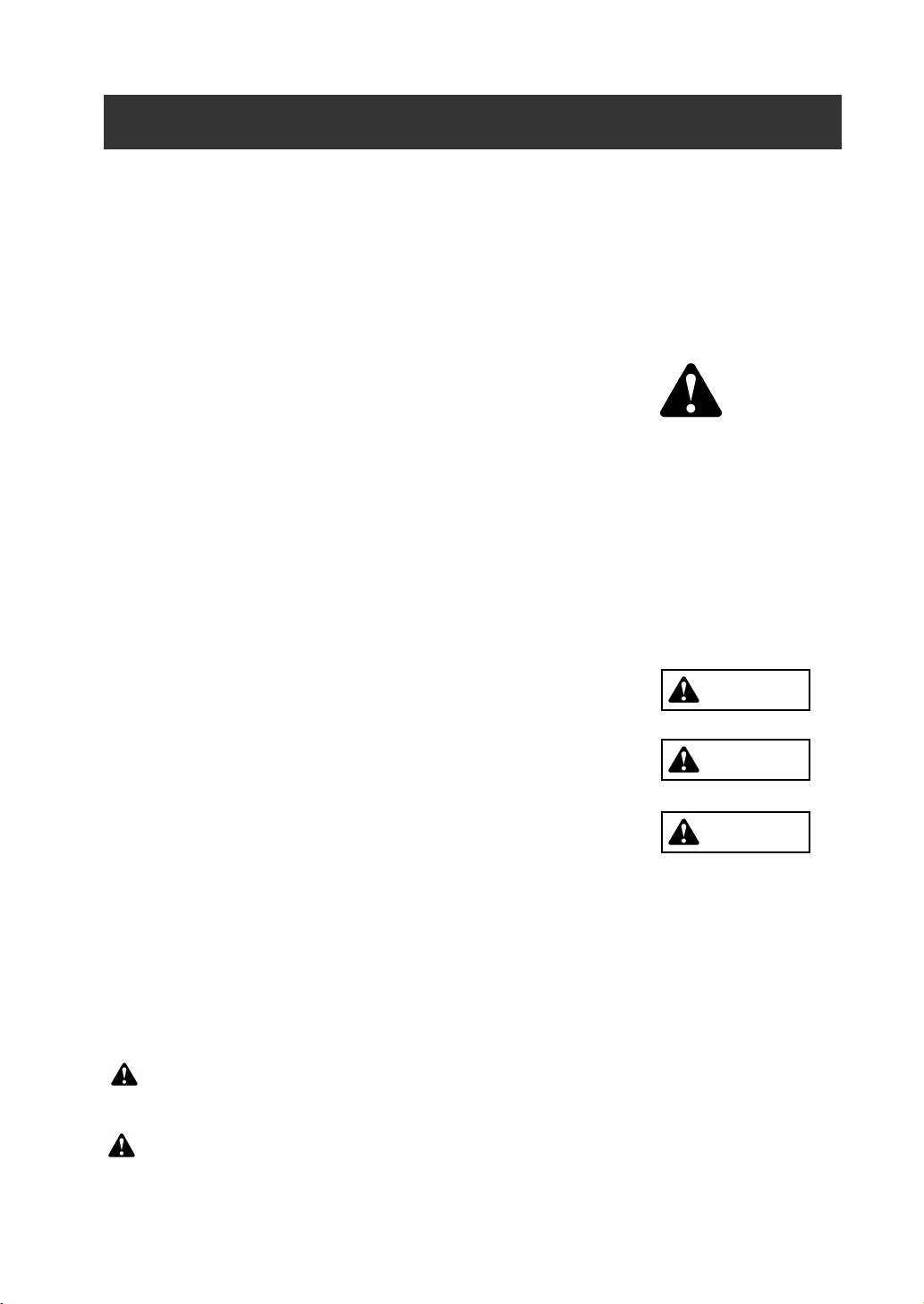
When current flows through a buried cable/pipe, an alternating magnetic field is generated around it.
Location, depth, and current value of the buried pipe can be measured using the Receiver at the surface of the ground.
- Feature -
· Adopting differential coil method makes the Receiver to receive the signal from direct below the Receiver by cutting noise from
surrounding area.
· Two kinds of the location measurement mode
*Peak mode: The method to detect maximum sensitivity. High precision.( having error detection protection function)
*Null mode: The method to detect minimum sensitivity point being indicated with arrow. (having error detection protection
function)
No switch operation needed. Applied to at deep depth with stable location work.
· Two kinds of the depth measurement mode
*0-5m (16ft) mode : Measurement of deep depth with high precision is possible at indirect method, the end of cable, and
jointing points.
*0-10m (30ft) mode : Stable measurement is possible at deep depth, near guardrail, or fence.
Do not use this mode with inductive mode.
· The Receiver itself can measure commercial frequency ( 50 / 60Hz, 100 / 120Hz) and Radio ( from 9k to 33kHz) without the use
of the Transmitter.
· The best-suited frequency is automatically selected at radio (9k - 33kHz) with search function.
· The measured data is stored (max. 400 data ) with one-touch operation.
The data can be transmitted to a PC as standard function.
· Broadcasting of four frequencies (512Hz, 9.5kHz, 38kHz, 80kHz) as usage meets various buried pipe.
· A Probe as an option can be used to detect nonmetal pipe.
2. Introduction
Signal
Magnetic field
Pipe / Cable
Signal
Magnetic field
Pipe / Cable
*The model figure of the differential coil.
The differential coil connected two coils for each other reverse.

- 4 -
3-1. Main equipment & standard accessories
Description Q’ty Remark
Transmitter Unit 1pc Used as a signal generator.
Receiver Unit 1pc Digital locator
Accessories
Connecting cable with a reel 1pc Used for Direct connection mode 5m/16.5ft.
Ground rod 1pc Used for Direct connection mode.
Type “D “Alkaline battery 8pcs LR20/13A For Transmitter
Type “AA” Alkaline battery 8pcs IEC LR6/NEDA15A For Receiver
Soft carrying case 1pc
Operating manual 1pc English version
Data viewer software 1pc CD, Operating manual
3-2. Optional equipment
Description Q’ty Remark
38kHz External coil 1pc Used for External coil mode.
9.5kHz External coil 1pc Used for External coil mode.
80kHz External coil 1pc Used for External coil mode.
Sewer Probe 1pc Used for non-metallic pipe.
Standard probe for 75mm/ 3" & 100mm/ 4" pipe.
Frequency: 38kHz or 512Hz
Mini probe 1pc For 25mm / 1" fiber optic duct.
For tracking non-directional drilling tools.
Frequency: 38kHz or 512Hz
RS232C Cable 1pc
Earphone 1pc Used in a noisy area.
3. Composition

- 5 -
Transmitter(TX)
Output frequencies 38kHz :38kHz
±
0.02% (Standard frequency)
9.5kHz :9.5kHz
±
0.02%
80kHz :78.125kHz
±
0.02%
512Hz :512Hz
±
0.02%
Dual :9.5kHz /38kHz
±
0.02%
Output power 5 watts maximum / 80kHz: 1 watts maximum
Operating Modes Direct connection mode, Inductive mode
External coil mode (optional )
Battery type Eight Alkaline LR20 “D”
Battery Life Direct mode : 50 hours (Output 4mA , 20
°
C / 68
°
F)
Inductive mode : 20 hours (Output 50% , 20
°
C / 68
°
F)
Full Power(5W) : 10 hours (20
°
C / 68
°
F)
Battery Status Low battery indication & Press key readout
Visual Indication LCD : Bar graph & Digital number, includes Backlight
Audio Indication Internal Speaker : Alarm, Beeping sounds
Measuring function Output Current : 0 to 300mA
Line Voltage : 0 to 250V
Output protection AC 250V ( 512Hz: Output is cut off automatically)
Operating Temperature
-20
°
C to 50
°
C / -4
°
F to 122
°
F
Dimensions 275
´
314
´
110mm (10.8”
´
12.4”
´
4.3”)
Weight 3.7kg/ 8.2lbs approx. including eight batteries
4. Specification

- 6 -
Receiver(RX)
Active Frequencies 38kHz : 38kHz
±
2%
9.5kHz : 9.5kHz
±
2%
80kHz : 78.125kHz
±
2%
512Hz : 512Hz
±
2%
Passive Radio Radio : 9k to 33kHz
Passive Power 50 / 60Hz : 5th harmonic ( 50 Hz or 60Hz user selectable)
100 /120Hz : 3ed harmonic ( 100 Hz or 120Hz user selectable)
Battery type Eight Alkaline LR6 “AA”
Battery Life 20 hours (20
°
C / 68
°
F)
Battery Status Continuous indication
Power save function Automatically power off after 5minutes of inactivity
Visual Indication LCD : Bar graph , Digital number & character, include Backlight
Depth Range Line : 0 to 5m /16ft. ( 0-5m / 0-16ft. mode)
0 to 10m /30ft. (0-10m / 0-30ft. mode)
Probe : 0 to 10m /30ft.
Depth Readout Unit Meter / ft. & inch
Depth Accuracy*1 2.0m / 6.5ft. :
±
2.5%
3.0m / 10ft. :
±
5%
5.0m / 16.5ft. :
±
10%
Current value Current value flowing on the conductor is displayed for line identity in
milli-Amps.
Audio output Internal Speaker (200 to 5kHz) , Earphone ( optional )
Data logging Memorized 400 points of the depth / current measurement data.
Interface D-sub 9-pin connector (RS-232C)
Operating Temperature
-20
°
C to 50
°
C / -4
°
F to 122
°
F
Dimensions 680
´
140
´
290mm ( 26.8”
´
5.5”
´
11.4”)
Weight 2.1kg/ 4.7lbs approx. including eight batteries
Note: *1 Locators are tested in the model field conditions with no adjacent signals.
Always excavate the line with non-destructive means before digging.
*2 Optional cable is necessary to read the logging data.

- 7 -
5-1. Transmitter
1) LCD window
2) Key function
POWER
Power ON / OFF
*Each time Transmitter is turned on the batteries are automatically checked.
ADJUST
Press ADJUST key after hook up to automatically adjust power.
FREQUENCY
Selects operating frequency.
*1 9-38kHz : Broadcasts both frequencies simultaneously in direct mode only.
*2 512Hz : Direct mode only
Battery indication
*The symbol appears when battery is low.
Increase Output power
Reduce Output power
LCD Window
Battery compartment
Touch pad
8-pin connector
Bar-graph (Output power / Battery status)
Backlight On / Off
Sound On
/ Off
Frequency / Output Power,/ Battery status
5. Description of parts & basic operation
MODE
Battery indication
38kHz
9.5kHz
9-38kHz
512Hz
80kHz
*1
*2

- 8 -
Light On/Off set
: Press
key while holding
(MODE).
Sound set
: Press
key while holding
(MODE).
: SOUND ON
: TRANSMITTER SOUND OFF, FUNCTION SOUND ON
: SOUND OFF.
Press and hold
&
for 2 seconds.
Note : The last setting is memorized after the unit is Turned OFF
3) 8-pin connector
The Direct connection cord or the External coil cord are plugged into the 8-pin connector.
4) Battery compartment
Replace all batteries when there is a low battery condition.
Use 8 3 1.5V alkaline type D (LR20 / 13A) batteries.
Close
Open
ALWAYS CHECK THE BATTERY POLARITY BEFORE
CLOSING THE COMPARTMENT
Put the rubber protector on
when not in use.
Transmitter sound :
Beep…(15sec.)…..Beep…(15sec)…Beep
Light On Light Off
MODE

- 9 -
5-2. Receiver
1)Key function
Power ON / OFF
*Power save function: Automatically power off after 5 minutes of inactivity.
Adjusts Signal sensi
tivity for PEAK MODE.
Depth measurement
: Press DEPTH key at the peak value spot.
Battery
compartment
Earphone plug
Signal input terminal
(8-pin connector)
Depth
Current index : Details page 25
Note: Current index is not displayed if probe is used.
Frequency
Receiving sensitivity
100% - 100%
30%
Magnetic
field
Gain Adjust Depth / Current Frequency
Note: 100% is not the maximum peak value. When 100% appears, press Gain key again
until a new sharp peak value is obtained, that is not 100%.
Bar-graph
Battery indication
Peak value spot = Top of the line
70%
50% 50%
Receiving sensitivit
y
Press GAIN key
20%
20%
30%
Press GAIN key
30%
Power Peak / Null Mode
Measuring Mode
RS232C
Connector
Power
Gain
Adjust
Depth /
Current
Null Mode
Peak Mode
Peak mode :Maximum sensitivity is the point directly
above the object line.
Null mode : Minimum sensitivity is the point directly above
the object line. The buried object line is
indicated with arrow.
Selects locating mode.
Peak / Null

- 10 -
Power on while holding Frequency key.
POW 50Hz or POW 60Hz screen is indicated in 1 seconds.
Press Frequency , and select 50Hz or 60Hz .
At the same time, 100/120Hz is selected. ( 50Hz Þ 100Hz / 60Hz Þ 120Hz )
The setting is memorized with Power off.
Various settings
1. Selects sound and backlight options. By pressing Mode , move on.
2. Selects Depth function. By pressing Mode , move on.
3. Selects PROBE detection. By pressing Mode , return to measurement.
When Sewer or Mini Probe is employed for the detection of Non-metallic pipe or Boring device.
Only 38kHz and 512Hz are used for Probe.
*The last setting is saved.
Press Gain : Select speaker sound On / Off.
S-ON : SOUND ON
S-OF : SOUND OFF
Press Depth : Select backlight On / Off.
L-ON : LIGHT ON
L-OF : LIGHT OFF
Press Depth : Select depth function 0-5m / 0-10m ( 0-16ft / 0-30ft.).
Press Frequency : Select detecting function .
*0-5m / 16ft : Applied for Inductive mode.
Detecting near t he end of the pipe.
Depth measurement range 0 to 5m(16ft).
Mode
80kHz
38kHz
9.5kHz
512Hz
60Hz
120Hz
RAD
Frequency
Selects operating frequency.
*RAD : Radio (passive 9kHz to 33kHz)
* 50Hz * 100Hz
Selects Power frequency 50Hz / 60Hz
CAUTION
When applying Inductive mode, select 0-5m /16ft . Depth measurement
error gets bigger at near the Transmitter when 0-10m/30ft is applied.
*0-10m / 30ft : Applied for the depth deeper than
5m(16ft.) , near guardrail or metal fence.
The measurement range of depth 0 to 10m(30ft).
PROB OFF .
Cable / Pipe detection
PROB ON .
Probe detection

- 11 -
Setting the Time and Date
a)Power on while holding Mode , wait for clock display appears.
The year will flash.
Press Gain to advance the year or Depth to decrement the year.
b) Press Mode , the month will flash.
Press Gain to advance the month or Depth to decrement the month.
c)Do same as above to set Day - -> Hour - - > Minute.
When measurement starts, setting is completed.
2) Battery compartment
Replace all batteries when there is a low battery condition.
Use eight 1.5V alkaline type AA (IEC LR6/NEDA15A).
3)RS2332C connector
A RS232C connector is provided for serial communications
to the personal computer.
*Interface cable is supplied as option.
*Specification of interface cable :
9-pin, D-SUB, straight connection
or same specification RS232C-USB conversion cable
Interface cable is available at market.
4)Earphone plug
Earphone can be used in a noisy area.
Supplied as an option.
5) 8-pin connector
Used with External Coil (9.5kHz or 38kHz) to find wiring
systems in a building or overhead telephone cables.
External coils are supplied as options.
Battery 0%
Battery 100%
Close
Open
When the batteries tray is stored, check the
ARROW should point up.
ALWAYS CHECK THE BATTERY POLARITY
BEFORE CLOSING THE COMPARTMENT
Earphone plug
8-pin connector
Mode

- 12 -
*Messages during your search procedure :
Receiving signal is too high.
a) Indirect mode : Transmitter and Receiver are too close each other.
b) Other cases : Reduce output of the Transmitter.
Receiving signal is too small or not present.
a) In the case of direct, induction or coil
- Increase output of the Transmitter.
- Check batteries, connecting parts and frequency of the Transmitter.
- Check signal loop at the Transmitter.
b) In the case of Radio / Power mode
- There are no conductors to radiate magnetic fields. There is no pipe or cable
- There is a conductor, but the signal is too low to adhere to the line. Use Transmitter
to search for the line.
*Messages on location :
Press GAIN key. Þ Normally this is your object line.
Reduces or increases signal strength.
*Messages on Depth measurement :
a) Received signal level is unusual, or received signal is too small.
b) Located point is not right above the object line.
c) Metallic fences, metallic structures or cars are interfering with the depth
measurement. Find area with less interference.
d) The Line is disconnected.
Indicating that the depth measured is deeper than 5 m / 16 ft.
In Line detection (0-5m / 0-16ft.) mode, locator cannot read below this depth
Indicating that the depth measured is deeper than 10m / 30ft.
In Line detection (0-10m / 0-30t.) or Probe detection mode, locator cannot read
below this depth.
6. Warning Message
OVER
LOW
PUSH
GAIN
ERR
16. --ft/in.
5. --m
30. --ft/in.
10. --m

- 13 -
Mode of Detection
Purpose of usage
This is the best way to inject AC current direct to the target line.
Signal (AC current) will return to the Transmitter through the
ground.
Effective for detecting the target line in congested areas.
Advantage for live power or cable, that is not accessible for
Direct connection.
The clamp is waterproof and will attach on any size cable.
No need for a ground stake.
Effective for detecting the target line in congested area.
The target line must be grounded.
If there is no direct access to the target line, use this method.
The Transmitter can induce its signal to the buried line.
Place the Transmitter in an upright position and at right angle to
the buried line.
Minimum TX to RX distanceÞ30 ft / 10 m
Note: When using the indirect mode, set the depth mode of the receiver
to 0-5m (0-16ft.) .Depth measurement error gets bigger at near the
Transmitter when 0-10m (30ft) is applied.
Used with External Coil to find wiring systems in the building.
TX's circuit is protected* up to 250V at 50 / 60 Hz.
*512Hz output is cut off automatically.
Used for tracing small diameter drains or plastic pipes.
Also, pinpoint a drain blockage or collapse. Can trace non-
directional boring tools.
The Probe is available in two sizes,
20mm/ 0.79" and 50mm / 2" diameter.
External Coil Mode
Direct Connection Mode
Building Wiring
Probe Mode
Indirect (Inductive) Mode
7. Operation of Transmitter (TX)
Signal
Black clip
Transmitter Red clip
Target line
Ground stake
Ground
Signal
Signal

- 14 -
7-1. Direct connection mode
A specific route can be detected in Direct Connection mode. Use two 5m/16.5 ft connecting cable with a
reel provided in the carrying case as one of the standard accessories.
When the clips are connected to the transmitter, Direct Connect
ion mode automatically selected.
Frequency setting
Connect the cable clips to the target line and ground stake.
Display of the Direct mode
Press FREQUENCY key
T
ransmitter
This Groove up
Before connecting, pull out proper
length of cable from the reel.
Note:
Place the Earth/Ground as far as possible and at right
angle to the object line.
Keep Receiver at least 5m/16ft. away from the signal
connection point as illustrated
90°
Receiver
Press Frequency key
Black clip
Ground stake
Red clip
Metal pipe
Note: Clean off if the connected part is rusted or
painted to ensure a good electrical connection.
Check the grounded point. Find the best place to
ground to have a GOOD SIGNAL LOOP
indication.
*Set a receiving frequency on the Receiver the same as
the transmitter.
Line

- 15 -
Check the signal loop
When signal loop is acceptable, Beeping sound is emitted.
Adjust output power
When output is adjusted
*When the Receiver indicates “ OVER” , Press
key.
Þ
Reduce output.
*W hen locating a long-distance line or deeper depth than 3m / 16ft., Press key.
Þ
Increase output.
Check the voltage when connecting clip to Power line.
- When voltage is greater than 20 volts, voltage is displayed.
- When voltage is greater than 25 volts, Alarm sounds.
Note: 512Hz output is cut off automatically.
Press ADJUST key.
*Transmitter will beep for 30 seconds.
*Sound stops when Press ADJUST key.
*Sound setting is [b-0].ÞBeeping sound off.
Automatically adjust power GOOD
SIGNAL LOOP
*When “GOOD SIGNAL LOOP” isn't indicated after pressing ADJUST.
Þ Clean off the connected part if rusted or painted or move ground stake.
Note:
Beeping sound is emitted after output is adjusted when the resistance value of the cable is high.
ELECTRIC SHOCK
Death or serious injury will result. 250 Volts maximum across
clips. Use protective equipment.
PEEEEEE!!!!
AC VOLTAGE
*Alarm stops when Press ADJUST key.
*Sound setting is [b-0]. Þ Alarm off.
。
P P P P ….
DANGER

- 16 -
Direct Connection mode
Use the Receiver 5m / 16ft. away from the
transmitter and clips.
Applications (1)
Applications (2)
If the dead cable is the object, connect the red alligator clip of the connecting cable to either the aluminum-sheath
or a bundle of the copper cores directly.
5m / 16ft. away
Power cable:
Disconnect common ground lead and
connect the Red clip to Power line ground
lead. Then locate Power line
Power cable
House meter
Common ground lead
Telephone cable:
Disconnect Telephone
Ground lead and connect
the Red clip to it to locate
Telephone line.
CATV cable:
Disconnect CATV's
ground lead and connect
the Red clip to it to locate
CATV line.
Telephone cable
CATV cable
Remember to correctly reconnect common grounds for telephone, CATV and Electric Lines.
Check Local codes for proper grounding procedure. IMPROPER GROUNDING MAY CAUSE
DAMAGE TO APPLIANCES, FIRE OR EXPLOSIONS.
WARNING
The ground should be provide
at
the end of the line
Short distance dead cable
Long distance dead cable
No need of ground at the ending point

- 17 -
7-2. External coil mode
Use 9.5 kHz, 38 kHz or 80kHz External coil supplied as an option. Use this mode if object is accessible.
An induced current, generated by the coil in the External Coil attachment, is applied directly to the exposed
part of the cable / pipe to be located.
Applicable to : Live Telecom cable or Live Power cable. Fiber optic cable having an aluminum-sheath.
When the External coil is connected to the transmitter, External coil mode is automatically selected.
Frequency setting
Adjust output power
Connect the External coil to the target line.
Note :Make sure it is attached parallel and in line with the cable as illustrated.
This Groove is up
External Coil mode indication
When 38kHz coil is
connected
Transmitting coil
*The jaws do not have to be closed around the cable.
(This coil method is different from the conventional clamp
that must have jaws perfectly closed. Different size clamps
are not needed. The Verifier coil method uses the indirect /
Inductive principle.)
Indicate output power with the bar
graph and the numerical value when
pressing / key.
Reduce output
power
increase output
power
Electromagnetic field
Telecom / Power cable
(Diameter up to 10cm / 4”)
Frequency is selected based on coil used
with the External coil automatically.
External coil
*Set a receiving frequency on the Receiver the same
as the transmitter.
Press Frequency key

- 18 -
External coil mode
Make sure that the cable is grounded at both ends.
Do not put the coil close to or around the ending or middle ground.
* If the cable is submerged in water, you can use the coil attachment in the water.
The coil attachment is WATERPROOF.
Note : Do not attach to the metal pipe or metal riser above the ground.
Attach the coil clamp to the cable/PVC part.
Note :
Use the Receiver more than 5 m/16 ft away from the coil clamp
when starting the location work.
5m / 16 ft. away
OK
Intermediate ground
Metal Pipe
PVC Pipe
Cable
Note : Fresh water has no effect Locating the cable or detecting depth.
Brash or salt water will effect locating.
Signal to ground
will not trace.
Table of contents
Other Takachiho Sangyo Measuring Instrument manuals