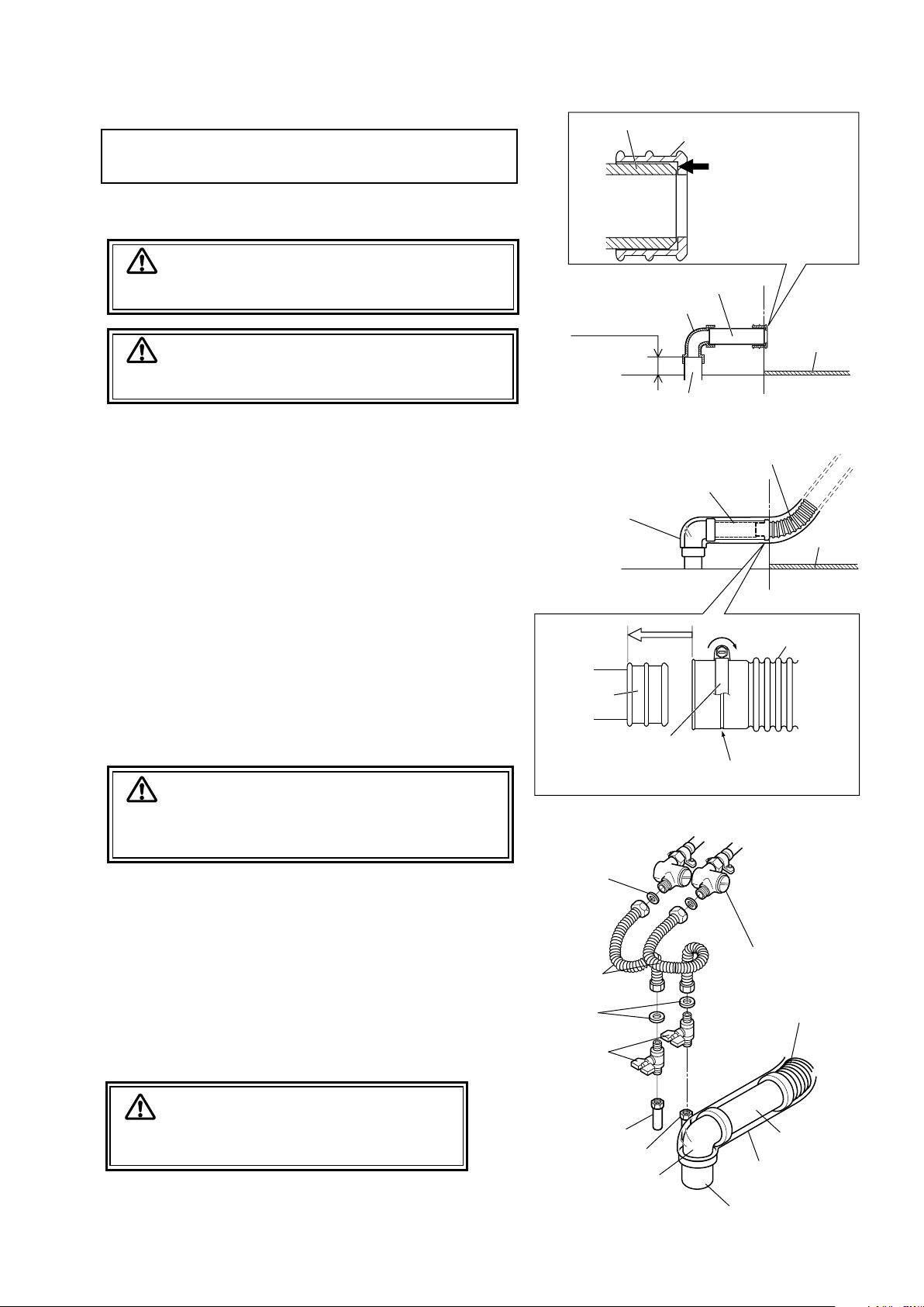
Takara Belmont YUME User manual

SHAMPOO UNIT
YUME
This manual provides information and instructions for YUME SHAMPOO
UNIT. The instructions contained in this booklet should be thoroughly read
and understood before attempting to install the equipment.
After the installation is completed, file this manual and refer back to it
for future maintenance.
IMPORTANT
INSTALLATION
INSTRUCTIONS
IE00G8A0

TABLE OF CONTENTS
INSTALLATION INSTRUCTIONS
1. Overall View and Major Components........... 1
2. Dimension & Specications.......................... 2
3. Plumbing Layout...........................................3
4. Contents of Unpacked Products .................... 4
5. Installation Instruction...................................5
5-1. Preparations for Installations
...................... 5
5-2. Installation of the Carriage Jig
.................... 5
5-3. Marking for unit xing position
.................. 6
5-4. Fix the Moistureproof sheet and packing
..... 6
5-5. Installation of unit
.......................................... 6
5-6. Drain Pipe Connection .................................... 8
5-7.
Water and Hot Water Supply Line Connection
.... 8
5-8. Unit Power Supply Line................................... 9
5-9. Installation of Base Cover................................ 9
5-10. Attach the backrest and seat cushion ............. 10
5-11. Attach the Neck Cushion................................ 11
5-12. Attach the Head Pillow .................................. 11

■Body
Backrest
Seat
Main switch
Shampoo basin
Maintenance cover Foot switch
Neck cushion
(Consumable)
Head pillow
(Consumable)
Shower head
Vacuum Breaker
Shower hose
Preset
DOWN
UPAuto Return
Backrest Raising Backrest Reclining
DOWN
UPAuto Return
Backrest Reclining Backrest Raising
Temperature control knob
Body cover
■Footswitch
EX-YML : left side foot switch EX-YMR : right side foot switch
Preset
Noise reduction tape
(inside cover)
Safety lock cover
1. Overall View and Major Components
-1-

2. Dimension & Specifications
-2-
6°
65°
760
595
75
28 35
650
520
950
600
975
450 170
Min.630(Sitting Position)
Min.430(Standing Position)
465
53103
7
Line for Edge of Base Plate
Drain Pipe
170
Min.215
1965
Min.2980(Sitting Position) / Min.2780(Standing Position)
880
1270
600 (Base Plate)
830
480
520
Wall
75
Water Supply
Hot Water Supply
Wall
Center of Drain Pipe
Type ------------------------------ EX-YML, EX-YMR, SU-YM
Drive System -------------------- Motorized Hydraulic System
Measurement -------------------- 760 x 1985 x 975 mm (W x L x H)
Angle of Bracket ---------------- 59° (6° 〜65°)
Type of Mixing ------------------ Thermo Mixing
Stop Valve ------------------------ Water x 1 (Handle Type) / Hot Water x 1 (Handle Type)
Electrical Requirements --------
AC120V 50/60Hz 5.8/4.4A
Usage Environment ------------ Operational Temperature (10 〜40°C)
Water and Hot Water ---------- 0.08 〜0.6Mpa (0.8 〜6kgf/㎠)
Supply Pressure ---------------- Water Supply Pressure
≧
Hot Water Supply Pressure
Pressure difference between water supply and hot water supply within 0.2Mpa (2kgf.㎠)
Water Volume (Shower Head)
---- 10ℓ/min (water and hot water pressure are 0.1 Mpa)
Weight --------------------------- 156 kg

3. Plumbing Layout
-3-
Bolt (anchor) fixed position
(Moistureproof Packing)
(Space of Plumbing)
Power Source
(Space of Plumbing)
(Moistureproof Packing)
Center to Wall or Center to Cabinet
(Including for customer
approach space)
Seat Side Bowl Side
From Wall or Cabinet
Edge of Base Plate
Footprint
Bolt (anchor) fixed position
Bolt (anchor) fixed position Bolt (anchor) fixed position
(Not including for customer
approach space)
Connected position of
power plug and power supply
outlet (Recommendation)
(Base Plate)
210
420
160
50 15
100
455
600 [Base Plate]
300
105
65
75
135
115
200
160
143 5
15
32
Min.1270mm Min.1730mm
95
(Cable should have 1000mm)
195
265
225
20
Drain VU40 (Height 60mm)
Hot Water 1/2” 13m/m(Height 50mm)
Water 1/2” 13m/m(Height 50mm)
430
28
75
35
80
480
215
Min.1000mm
Min.800mm
( 8-9/32”)
( 16-17/32” )
( 6-5/16” )
( 1-31/32” ) ( 19/32” )
( 17-29/32” )
( 3-15/16” )
( 23-5/8” )[Base Plate]
( 11-13/16” )
( 4-1/8” )
( 2-9/16” )
( 2-15/16” )
(5-5/16” )
( 4-17/32” )
( 7-7/8” )
( 6-5/16” )
( 5-5/8” ) ( 3/16” )
( 19/32” )
( 1-1/4” )
( Min.50” ) ( Min.68-1/8” )
( 3-3/4” )
(Cable should have 39-3/8” )
( 7-11/16” )
( 10-7/16” )
( 8-27/32” )
(25/32”)
( 2-3/8”)
( 2”)
( 2”)
( 16-15/16” )
( 1-3/32” )
( 2-15/16” )
( 1-3/8” )
( 3-5/32” )
( 18-29/32” )
( 8-15/32” )
(Min.39-3/8”)
(Min.31-1/2”)
Metric (Imperial)

・Neck Cushion
・Head Pillow
・Drain Cap ・Hair Catcher
・Floor Bolts
M8×70 Anchor Bolt x8
M8×65 Hex Head Tap Bolt x8
Flat Washer ×8
・
Moistureproof
Sheet
・Moistureproof
Packing (Sponge)
・Water Stop
Valve
・Flexible Pipe ・Drain Hose Packing ・Drain Hose Clamp
・Noise Reduction Tape
4. Contents of Unpacked Product
•YUME Main Body
•Seat and Backrest set
・SeatCushion ・SeatCover(R) ・SeatCover(L)
・BackrestCushion ・BackrestCover
・Screws
• Jig A
• Jig B Bracket
• Jig B
• Jig B Support Bar
・Screws
•Carriage Jig
-4-
※Elbow and drain pipe(VU40) are NOT INCLUDED with shipment. Please prepare it beforehand.

-5-
5. Installation Instruction
1. Unpacking
Remove nails from lower part of wooden crate.
Lift up the upper potion of wooden crate.
Chair will be left on the skid.
2. Remove the pump cover.
1. Remove the screws and remove maintenance cover,
base cover left and right from main body.
2. Remove the oil plug with red tag from oil reservoir.
3. Plug the unit power supply plug in to the
suitable power supply outlet.
4. Turn on the main switch located on the left side
of base.
5. Keep depressing UP button of foot switch
until the seat is lifted up to the end.
6. Turn off the main switch
7. Unplug the unit power plug from power supply outlet.
5-1. Preparations for Installations
Nails
Nails
Oil Plug with Red Tag
Maintenance Cover
Base Cover(R)
Base Cover(R)
Oil Reservoir
Main Switch
Foot Switch
Note : Do not remove the unit from the pallet
until the unit fixing position is ready.
Holding the Carriage Jig and place it at
planned location. Do not carry by holding
the body or basin.
5-2. Installation of the Carriage Jig
1. Fix the Jig A to the base.(M10 x 30)
2. Fix the Jig B bracket to the base.(M10 x 50)
3. Attach the Jig B support bar to the
Jig B bracket.
4. Attach the Jig B to the Jig B support bar
and tighten the nuts.(M16)
CAUTION
Do not turn on power during installation.
Base
1 Jig A
2 Jig B Bracket
4 Jig B
3 Jig B Support Bar
Screws
M10 x 30
Screws
M10 x 50

Moistureproof Sheet
Moistureproof
Packing
Moistureproof Packing
Seal a space
around here
5-4. Fix the Moistureproof sheet and packing
Please obtain the moistureproof sheet and the moistureproof packing to prevent from the
main body damaged by the moisture. Deterioration and the breakdown of structural parts
and electrical equipments might not be occurred without the installation.
1. Fix the moistureproof sheet on the oor.
Plywood Floor : Wood Screw
Concrete Floor : Glue
2. Make a cut in the moistureproof packing according to piping position.
3. Peeled off the sheet on the adhesive face side of the moistureproof packing. Passes under the
piping and electric code on the moistureproof packing and attach to the oor.
4. Seal a space around the piping and electric code.
5-5. Installation of unit
1. Remove the four tapping screw(M8 x 60mm) xing the
unit base plate to the pallet.
Marking
Water Supply
Hot Water Pipe
Drain Pipe
Power Outlet
Pipe
5-3. Marking for unit xing position
Use supplied full scale template to mark the
xing position on the oor. Check the piping
and power outlet position before marking.
1. Put the supplied templete on the oor and hold with
the tape etc. It should be set to the position of
piping and power outlet.
2. The chair xing position is marked on the oor.
3. Make it holes for marked position. (8.5 mm x 50 mm )
4. Remove the template from the oor.
Base
Tapping Screw(M8 x 60)
Pallet
-6-

-7-
→
Templete
8.5 mm
50mm
or more deep
Floor
2〜5mm
CAUTION
Base Plate
Hammer
Flat Washer
Nut
Center pin
If the anchor bolt is tapped with its and contacting the bottom
of the hole, the strength will be lowered. Proper clearance
must exist between the end of the anchor bolt and the bottom
of the hole.
Do not make scratch or damage the floor while moving the
unit. Please use the carriage jig to move it.
4. Fix the main unit with the four screws.
Plywood Floor : Hex head tapping screw M8 x 65
Concrete Floor : Anchor bolts M8 x 70
5. When the moistureproof packing is bigger than
main unit base, please cut it out.
Construction process of anchor bolts.
1.Drill the anchor holes
of a specific diameter
and depth.
2.Clean each anchor hole
thoroughly using a
vacuum cleaner, with a
tnemhcattaelzzonworran
to reach into the hole and
remove all debris.
3.Insert the anchor bolt, tapping
it lightly with a hammer to seat
it. Position the material, and
then drive the center pin into
the anchor unit it is snug.
4.Adjust the fastening strength
of the nut using a wrench etc.
Hold the Jig A and B to lift the unit by
2 workers to move it. Otherwise, breakage
may result in.
CAUTION
Carriage Jig A
Carriage Jig B
2. Hold the carriage jig and move the main unit to
marked position on the floor.
3. Decide the installation position and remove the
carriage jig A and B from main unit base.

-8-
Check Valve
Flexible Pipe
Packing
Stop Valve
Water Supply
Hot Water Supply
Drain Hose
Vinyl
Drain Pipe
Elbow
Packing
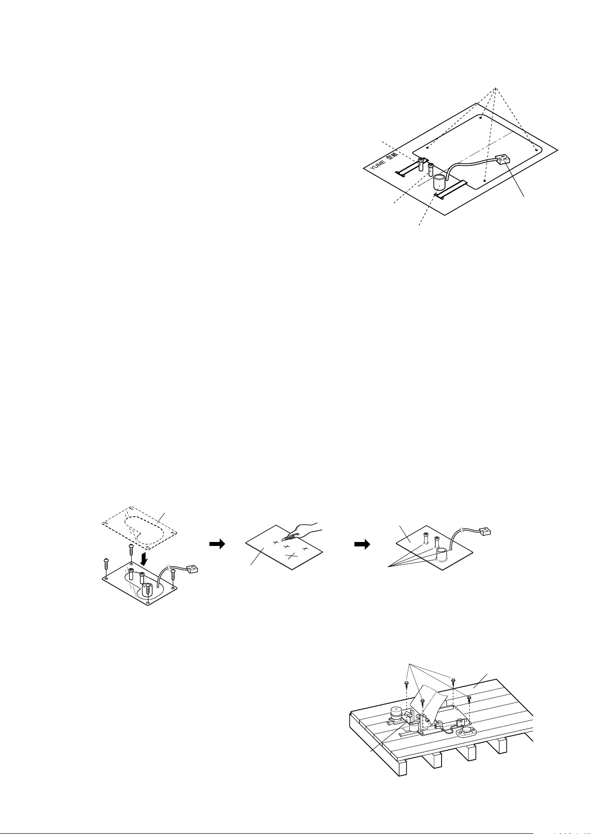
The height of drain pipe should be less than 60mm.
CAUTION
1. Insert the elbow to the drain pipe from floor with seals.
2. Adjust the length of drain pipe(VU40), so that the
one end of drain pipe(VU40) may become on the
edge of the base, and connect to elbow with seals.
3. Connect the drain hose packing to the drain pipe(VU40).
4. Through the drain hose clamp to the drain hose, and
connect the drain hose to the drain hose packing.
•The drain hose shall be free of dent.
•Attach the drain hose so as not to be folded.
5. Fasten the screw of the drain hose clamp for
drain hose.
•Tightening too hard may damage the drain hose.
Do not tighten too hard.
6. Cover the elbow part with the vinyl.
5-6. Drain Pipe Connection
5-7. Water and Hot Water Supply Line Connection
1. Install the stop valve to each supply pipe.
2. Bend each flexible pipe to a suitable angle for
connection.
Check the each connection for leaks.
3. Connect the each Check Valve to the each stop
valve with the flexible pipe.
Make sure all connection is surely fixed.
please confirmed the water does not leak.
Drain Pipe(VU40)
CAUTION
CAUTION
Elbow and drain pipe(VU40) are not included
with shipment. Please prepare it beforehand.
Do not tear up the vinyl which is covered the drain hose.
CAUTION
F.L.
F.L.
Drain Hose Packing
Drain pipe(VU40)
Stepped Section
Drain pipe(VU40)
Elbow
Less than 60mm
Drain Pipe
from Floor
Edge of Base Plate
Base Plate
Insert the drain hose packing
to the drain pipe(VU40) until
the stepped section hit to the
end of drain pipe(VU40).
Drain Hose
Base Plate
Edge of Base Plate
Vinyl
Drain pipe(VU40)
Drain Hose
Packing
Drain Hose Clamp
Drain Hose
Insert it in
this line
Match the center of the drain hose clamp
to this line of the drain hose.
Fastening

-9-
Base Cover(R)
Base Cover(L)
Center base cover
Maintenance Cover
Oil Reservoir
Oil Plug with
Red Tag
2. Fix the base cover left & right with screws(M4 x10).
1. Remove the oil plug red tag from the oil reservoir.
4 Fix the maintenance cover
CAUTION
The main switch does not enter by
mistake when attaching the base cover
3. Fix the center base cover with screws
and plastic washer (M5 x 20).
Screw
Plastic Washer
Attach the maintenance cover
to the base cover left & right
and fixed with screw(M4 x 10)
5-9. Installation of Base Cover
Power Supply Cable
Power Supply Outlet
5-8. Unit Power Supply Line
1. Fix the plug on the end of the unit power supply cable.
Plug the unit power supply plug into the suitable
power supply outlet.
CAUTION
This appliance is equipped with a cord having an
equipment-grounding conductor and a grounding plug.
The plug must be plugged into an appropriate outlet that
is properly installed and grounded in accordance with
all local codes and ordinances.

-10-
4. Backrest Cushion
Connection Strut
Backrest Frame
2.Seat Cover(L)
Insert
Apron
1.Seat Cushion
2.Seat Cover(R)
3.Raising Button
6.Backrest Cover
Backrest
6.Raised the cylinder cover
5.Apron
Cylinder
5-10. Attach the backrest and seat cushion
1. Fix the seat cushion with six cap bolts(M5×15)
2. Fix the seat cover L & R with screws.
3. Keep depressing backrest raising button
until the backrest frame is raised position.
4. Attach the backrest cushion to the backrest
frame and fixed with screws(M6 x 20)
6. Attach the backrest cover and fixed with six
screws(M4 x 18)
5. The apron from seat cushion is inserted between
the backrest cushion and the cylinder,then fixed
with two screws(M4 x 18)
Attach the backrest cushion
vertical to the backrest frame.

-11-
Neck Cushion
Hook
Hook
Metal Fitting
Head Pillow
Hook
Fixed Pin
5-11. Attach the Neck Cushion
1. Attach the neck cushion on metal fittings
as shown in figure.
2. Both side hooks of the neck cushion is fixed on a fixed pin.
5-12. Attach the Head Pillow
1. Attach the head pillow as shown in figure.

NOTE
101 Belmont Dr., Somerset, NJ 08873
TEL. : Toll Free (866) 4 TAKARA (866-482-5272)
TELEFAX : 732-469-9430
TAKARA BELMONT U.S.A., INC.
Other manuals for YUME
3
Table of contents
Other Takara Belmont Hot Tub manuals
Popular Hot Tub manuals by other brands

NETSPA
NETSPA VITA PREMIUM Installation and user manual

Aquatic
Aquatic HOTSOAK 92 AI35AIR6036HS Specification sheet

Solana
Solana DRAFT 10 owner's manual

Grizzly Bear
Grizzly Bear Fusion Rs owner's manual

Dimension One Spas
Dimension One Spas Home Hot Tubs Planning and installation guide

M-Spa
M-Spa Lite LS04-NA owner's manual

Baja Products
Baja Products Whitewater XS owner's manual

BullFrog
BullFrog X Series owner's manual

Sanotechnik
Sanotechnik SanoSpa SPA08 Instructions for using

Intex
Intex PureSpa SSP-H-20-1 owner's manual

Sundance Spas
Sundance Spas Denali 680 Series owner's manual

sanowell
sanowell ActiveSpa bubble spa manual