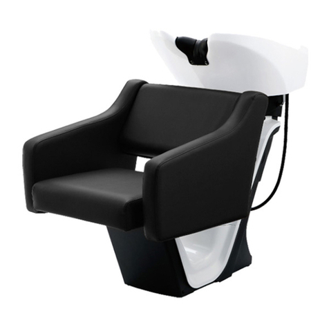
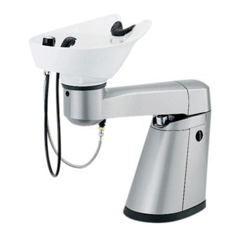
Takara Belmont KAZE AY-KFPLU AY-NRS1 User manual

Chair Mount Type
Separate Type
Installer: Read through this installation manual to ensure proper installation.
Leave this manual to the owner after installation completed.
Owner: Keep this manual in a safe place for your future reference.
NRS Installation Manual
Standard / EU Spec.
KAZE
(AY-KFPLU AY-NRS1 is shown.)
OTO
(AY-OLL AY-NRS1 is shown.)
(AY-NRS2B-W is shown.)

2
Before Installation
Plumbing
This section includes important information about plumbing.
Please understand the content fully for proper plumbing.
• Please follow the "Notes in plumbing" when plumbing. If not followed, the water mixing may not
work properly and hot water of specific temperatures will not come out.
• This product is designed for the use indoors.
Notes in plumbing
Do NOT use a material which rusts easily for water supply pipes.
Use VP pipes or other designated material in your area as a standard.
Use deacidified cupper pipes for hot water supply pipes as a standard.
Use the pipes of same diameter and for same pressure for both hot water supply and
cold water supply pipes.
Ream the cut face of the pipes to clear the face of burrs.
Avoid using a reverse U-shape pipe. This may cause air trapping.
Plumbing refuses, dust, sand or oil in the hot water supply pipe and cold water supply
pipe may cause trouble. Remove them before connecting pipes.
After plumbing and a flow test are completed, clean the strainer and the shower head.
Adjust the inclination of the drain pipe to be at least 1/50 for the pipe of 100 or less,
and at least 1/100 for the pipe of 100 or more.
Do not mix up the cold water supply pipes and the hot water supply pipes. Connect the
pipes in the correct combination.
Arrange the hot water supply line in a shortest distance from the water heater so as to
minimize the resistance. With longer distance, temperature of hot water may fluctuate or
water amount may be reduced.
Cover the pipes with heat insulating material after plumbing completed.
Plumbing particulars for boiler
• Main pipes of same diameter and for same pressure must be used for both hot water
supply and cold water supply as a standard.
•A boiler must be installed by a qualified installer.
This product is equipped with a deodorant trap.
CAUTION
This mark warns the user that "improper use may cause personal injuries or material damages".
Definition of markings
These markings indicate important information to avoid personal injuries, or property damages
against you or your customers by using this product correctly. All instructions are important for safety
operation. Please be sure to observe them.

3
Requirements for Use
Requirements for hot/cold water supply
Floor
Make sure that the floor is level.
Make sure that the installation area is flat and free of irregularities.
Use floor panels with high water resistance.
Raising pipes
In the case where the floor is finished with tiles etc., screwing bolts into the floor
surface when installing the shampoo unit may cause a crack on the floor surface.
Change the material of the floor of the installation area to plywood, mortar, etc.,
referring to the product layout drawing and the pattern paper.
* The floor panel must have the strength as shown below.
Waterproofing
• In case of the installation on the second floor or higher, waterproof the floor
appropriately.
• Drinking water (Non-drinkable well water, or water including sand or rust are not
approved for use.)
• If the water hardness is 80 ppm or more, treat the water with a water softener in
order to prevent scale clogging of the equipment.
• Set the pressure within the range from 0.08 MPa to 0.6 MPa (0.8 to 6 kgf/cm2).
• When the pressure exceeds 0.2 MPa (2 kgf/cm2), select the floor unit "with
pressure reducing valve" type.
• The cold water supply pressure must be equal to or higher than the hot water
supply pressure.
• The difference between the cold water supply pressure and the hot water
supply pressure must be 0.2 MPa (2 kgf/cm2) or less.
• The temperature of hot water supply must be at least 10˚C higher than that of
hot water from the shower.
Water for use
Pressure of hot/
cold water supply
Temperature of
hot water supply
Cold/Hot water
supply
Drain
Wooden floor
Mortar floor
strength of plywood of 30 mm thickness or more
strength of mortar of 50 mm thickness or more
Rc1/2" Floor raising pipe
Raising height: Hot water supply 80 mm, Cold water supply 110 mm
VU40 Floor raising pipe Raising height: 90 mm
Special floor
(stone etc.)
a base with the strength equivalent to the above must be installed at the
installation position.

4
W-footrest
Rear cover
Floor footrest
Front cover
Base cover
Stop valve Frame receiver
cover
Neck cushion
or
or or
Set of screws
for cover
Chair mount
frame cover
(For chair mount
type only)
• Chair fixing screws
M8 x 70 Hex bolt (with plain washer and spring washer) x 4
• Footrest fixing screws (for U-footrest and W-footrest only)
M8 x 30 Hex bolt (with spring washer) x 4
• Chair (KAZE) • Chair (OTO)
Chair side (Not provided for separate type)
Shampoo unit side
• Shampoo unit
• Stop valve
• Neck cushion
• Shampoo unit floor fixing screw
M8 x 70 Anchor bolt
M8 x 65 Hex head tapping bolt
Plain washer
*Separate type: x 6
• Operation Manual, Installation Manual,
Pattern Paper
Cover set
Packing Material (Standard spec.)
(AY-KFPL- is shown.) (AY-OLL is shown.)
U-footrest
• Footrest
Chair mount frame
(Not provided for separate type)
x 8

5
W-footrest
Rear cover
Floor footrest
Front cover
Base cover
Stop valve Frame receiver
cover Neck cushion Base bracket
or
or or
Set of screws
for cover
Chair mount
frame cover
(For chair mount
type only)
• Chair fixing screws
M8 x 70 Hex bolt (with plain washer and spring washer) x 4
• Footrest fixing screws (for U-footrest and W-footrest only)
M8 x 30 Hex bolt (with spring washer) x 4
• Chair (KAZE) • Chair (OTO)
Chair side (Not provided for separate type)
Shampoo unit side
• Shampoo unit
• Stop valve
• Neck cushion
• Shampoo unit floor fixing screw
M8 x 70 Anchor bolt X 6
M8 x 50 Hex head tapping bolt x 6
Hex bolt (with spring washer) x 4
Plain washer x 10
• Operation Manual, Installation Manual,
Pattern Paper
Cover set
Packing Material (EU spec.)
(AD-KFPL- is shown.) (AD-OLL is shown.)
U-footrest
• Footrest
Chair mount frame
(Not provided for separate type)

6
Bolts to be used
(Accessory to shampoo unit):
Plywood floor:
Hex head tapping bolt +
Plain washer (8 mm x 65)
Concrete floor:
Anchor bolt + Plain washer
(M8 x 70, Anchor hole 8.5 m/m)
(Use a wrench with across flat 12 mm.)
Marking
1Lay the accessory pattern paper on the floor at the installation position referring to the raising positions of
cold/hot water supply pipes and tape the pattern paper.
2Mark the floor with a pencil at the positions of the shampoo unit base and the screw holes.
3Remove the pattern paper.
CAUTION
When using anchor bolts, do not use the spare hole in the
rear side. The bolts will make contact with the cover.
CAUTION
If the anchor bolt is tapped with its end contacting the bottom of the hole, the strength will be lowered. Proper
clearance must exist between the end of the anchor bolt and the bottom of the hole.
CAUTION
• Be sure to use the chair mount frame packing when fixing the chair mount frame.
• Be sure to use the plain washer when tightening the bolt.
• The center of the shampoo unit must be aligned with the center of the chair mount frame. (The
center of the chair mount frame is the notch of the chair mount frame packing.)
1
Fixing the shampoo unit.
1Detach the four screws on the shampoo unit.
2Attach the chair mount frame to the shampoo unit. Then fix the shampoo unit temporarily with the screws
detached in 1 .
3Fix the chair mount frame on the floor at the marked
position.
4Tighten the screws that were loosely fastened in 2 .
2
Anchoring procedure
Installing Shampoo Unit (Standard spec.)1
Chair mount frame packing
Center line
8.5 mm
Depth of
anchor hole:
Min. 50 mm
Pattern
paper
Floor
Rod
2 to 5
mm
Plain
washer Nut
4Adjust the fastening strength
of the nut using a wrench etc.
3Insert the anchor, tapping it
lightly with a hammer to seat
it. Position the material, and
then drive the rod into the
anchor until it is snug.
2Clean each anchor hole
thoroughly using a vacuum
cleaner, with a narrow nozzle
attachment to reach into the
hole and remove all debris.
1Drill the anchor holes of a
specific diameter and depth.
*

7
Attaching the chair mount frame cover and frame receiver cover.
Attach the chair mount frame cover on the chair mount frame.
3
Chair mount
frame cover
Place the frame
receiver cover on
the chair mount
frame and press it
firmly to the end.
Bowl rear side
Chair mount bracket
Notes in moving the shampoo unit
• When moving the shampoo unit, hold the shampoo unit at the rear side of the bowl and the mount base.
Do not hold the mixing pipe in the rear side of the bowl.
• Move the shampoo unit carefully and deliberately. The bowl is heavy and easy to break.
• Do not drag the shampoo unit. If dragged, the metal portion of the mount base and the frame may
damage the floor.
CAUTION
Do not move the shampoo unit
with the chair mounted.
Mount base

8
Mounting Chair (Standard spec.)2
Footrest
Mount pipe
Mount pipe
Chair mount bracket
Chair mount bracket
Line
Chair mount frame
Bolts to be used (Accessory to the chair):
M8 x 70 Hex bolt
(with spring washer and plain washer)
(Use a wrench with across flat 12 mm.)
Bolts to be used (Accessory to the chair):
M8 x 30 Hex bolt x 4
(with spring washer)
(Use a wrench with across flat 12 mm.)
Attaching to the chair mount frame.
1Place the chair on the chair mount frame with aligning the
centers of the mount pipes (4 pipes) in the back of the chair
with the lines on the side of the chair mount bracket of the
chair mount frame.
2Fix the chair to the frame with the bolts from below. (4
points)
1
Attaching the footrest (U-footrest, W-footrest).
Align the holes on the ends of the footrest with the holes on the back of the seat. Fix the footrest to the chair
with the bolts from the back of the seat.
2

9
Bolts to be used:
Hex bolt x 4
(with spring washer)
Marking
1Lay the accessory pattern paper on the floor as a template at the installation position referring to the raising
positions of cold/hot water supply pipes and tape the pattern paper.
2Trace the positions of the shampoo unit base and the screw holes onto the floor.
3Remove the pattern paper.
1
Installing the base bracket.
2
Installing Shampoo Unit (EU spec.)1
Fix the base bracket with accessory bolts on the floor at the marked position.
Rear of the bowl
Notes in moving the shampoo unit
• When moving the shampoo unit, hold the shampoo unit at the rear side of the bowl and the mount base.
Do not hold the mixing pipe in the rear side of the bowl.
• Move the shampoo unit carefully and deliberately. The bowl is heavy and easy to break.
• Do not drag the shampoo unit. If dragged, the metal portion of the mount base and the frame may
damage the floor.
Mount base

10
Bolts to be used
(Accessory to shampoo unit):
Plywood floor:
Hex head tapping bolt + Plain washer
(8 mm x 50)
Concrete floor:
Anchor bolt + Plain washer
(M8 x 70, Anchor hole 8.5 m/m)
(Use a wrench with across flat 12 mm.)
Fixing the shampoo unit.
1
Attach the shampoo unit to the base bracket securely.
2Detach the four screws on the shampoo unit.
3Attach the chair mount frame to the shampoo unit.
Then fix the shampoo unit temporarily with the
screws detached in 2 .
4Fix the chair mount frame on the floor at the marked
position with the chair mount frame packing inserted.
5Tighten the screws that were loosely fastened in 3 .
CAUTION
When using anchor bolts, do not use the spare hole in the
rear side. The bolts will make contact with the cover.
CAUTION
If the anchor bolt is tapped with its end contacting the bottom of the hole, the strength will be lowered. Proper
clearance must exist between the end of the anchor bolt and the bottom of the hole.
CAUTION
• Be sure to use the chair mount frame packing when fixing the chair mount frame.
• Be sure to use the plain washer when tightening the bolt.
• The center of the shampoo unit must be aligned with the center of the chair mount frame. (The center of
the chair mount frame is the notch of the chair mount frame packing.)
3
Anchoring procedure
Attaching the chair mount frame cover and frame receiver cover.
Attach the chair mount frame cover on the chair mount frame.
4
Chair mount
frame cover
Place the frame receiver
cover on the chair mount
frame and press it firmly to
the end.
8.5 mm
Depth of
anchor hole:
Min. 50 mm
Pattern
paper
Floor
Rod
2 to 5
mm
Plain
washer Nut
4Adjust the fastening strength
of the nut using a wrench etc.
3Insert the anchor, tapping it
lightly with a hammer to seat
it. Position the material, and
then drive the rod into the
anchor until it is snug.
2Clean each anchor hole
thoroughly using a vacuum
cleaner, with a narrow nozzle
attachment to reach into the
hole and remove all debris.
1Drill the anchor holes of a
specific diameter and depth.
Chair mount frame packing
Center line

11
Mounting Chair (EU spec.)2
Footrest
Mount pipe
Mount pipe
Chair mount bracket
Chair mount bracket
Line
Chair mount frame
Bolts to be used (Accessory to the chair):
M8 x 70 Hex bolt
(with spring washer and plain washer)
(Use a wrench with across flat 12 mm.)
Bolts to be used (Accessory to the chair):
M8 x 30 Hex bolt x 4
(with spring washer)
(Use a wrench with across flat 12 mm.)
Attaching to the chair mount frame.
1Place the chair on the chair mount frame with aligning the
centers of the mount pipes (4 pipes) in the back of the chair with
the lines on the side of the chair mount bracket of the chair
mount frame.
2Fix the chair to the frame with the bolts from below. (4 points)
1
Attaching the footrest (U-footrest, W-footrest).
Align the holes on the ends of the footrest with the holes on the back of the seat. Fix the footrest to the chair
with the bolts from the back of the seat.
2

12
Flexible pipe
Packing ring
Stop valve
Drain
Hot water
supply pipe
Cold water
supply pipe
Drain hose
The joint must be sealed.
VU40
Min. VU50
(VU40 acceptable when installing one unit only)
Raising drain pipe
CAUTION
The raising height of the drain pipe
must be 90 mm. Do not cut the
raising drain pipe short.
Plumbing (Standard / EU spec.)3
• Be sure to use the accessory packing
ring when attaching the flexible pipe. If
not used, there may be a risk of water
leakage.
• Do not mix up the cold water supply
pipes and the hot water supply pipes.
Attaching the drain pipe.
1Insert the drain hose with a bearing
sleeve to the raising drain pipe.
2Press the bearing sleeve to the drain pipe
and fit it into the drain pipe so that the
drain hose and the drain pipe are connec-
ted tightly.
3Fix the bearing sleeve into the raising
pipe tightly using a tape, adhesive, etc.
Attaching the flexible pipe.
Clean the piping area of plumbing refuses such
as dust, sand and oil first.
Attach the stop valves to the cold water supply
pipe and the hot water supply pipe. And then
attach the flexible pipes together with the
accessory packing rings to the stop valves.
1
2

13
Attaching Covers4
Attaching the base cover.
Attach the base cover to the unit and fix it with
two screws.
1 Attaching the rear cover.
Attach the bottom of the rear cover to the unit
first. Then fix the rear cover with two screws to
allow the mixing hose to pass through the rear
cover hole.
2
Attaching the front cover.
Attach the top of the front cover to the unit first
and fix it with two screws.
3
Base cover
Base cover
Sectional view
Attach
Mixing hose
Rear cover
Stainless
cover
Front cover
Stainless cover
Stainless
cover
Rubber tube
Frame
Front (Rear)
cover
CAUTION
When attaching the front (rear) cover, securely
push the stainless cover into the rubber tube
attached to the front (rear) cover. If not, the
water may go through the unit.

14
KAZE
Chair Mount Type
(AY-KFPLW AY-NRS1 is shown.)
572
450
320
440
515
500 (Seat height)
900 (Neck height)
(295) (1180)
1340 (with U-footrest)
1480 (with W-footrest)
Center of piping
314
365
(Raising height)
Hot water: 80 mm
Cold water: 110 mm
Drain: 90 mm
* The dimension in parentheses is a reference value.
Plumbing Drawing (Standard spec.)

15
*
The distance between the end of the leg rest and the wall or the furniture shall be at least 650 mm.
OTO
(AY-OLL AY-NRS1 is shown.)
500 (Seat height)
670
450
440
515
900 (Neck height)
(1180)
1515 (with leg rest)
Center of pipe
314
365
(Raising height)
Hot water: 80 mm
Cold water: 110 mm
Drain: 90 mm
* The dimension in parentheses is a reference value.

16
Separate type
(AY-NRS2 is shown.)
(Raising height)
515
440
900 (Neck height)
314
Center of piping
365
869
Hot water supply: 80 mm
Cold water supply: 110 mm
Drain: 90 mm

17
Plumbing Drawing (EU spec.)
KAZE
Chair Mount Type
(AD-KFPLW AY-NRS1 is shown.)
572
450
320
440
515
500 (Seat height)
950 (Neck height)
(295) (1200)
1360 (with U-footrest)
1500 (with W-footrest)
Center of pipe
314
365
(Raising height)
Hot water: 80 mm
Cold water: 110 mm
Drain: 90 mm
* The dimension in parentheses is a reference value.
Mount
bracket

18
*
The distance between the end of the leg rest and the wall or the furniture shall be at least 650 mm.
OTO
(AD-OLL AY-NRS1 is shown.)
500 (Seat height)
670
450
440
515
950 (Neck height)
(1200)
1535 (with leg rest)
Center of pipe
314
365
(Raising height)
Hot water: 80 mm
Cold water: 110 mm
Drain: 90 mm
* The dimension in parentheses is a reference value.
Mount
bracket

19
Separate type
(AY-NRS2 is shown.)
(Raising height)
515
440
950 (Neck height)
314
Center of piping
365
Hot water: 80 mm
Cold water: 110 mm
Drain: 90 mm

Checking after installation.
Check the following points.
1All bolts and screws, etc. are attached.
2The shampoo unit and chair are securely attached.
If there is a slack in the shampoo unit or the chair, check if the bolts at the attaching
portions are fastened tightly.
Attaching the neck cushion.
CAUTION In order to prevent accidents during operation, be sure to check that
Attach the nec
k cushion
by
f
ollo
wing the
procedure belo
w.
After Installation (Standard / EU spec.)
CAUTION
Do not lose the f
astener pin.
Place the nec
k cushion in the depression of the
bo
wl and fit it on the edge of the bo
wl.
(Please
pa
y attention to the direction of bac
k and
fo
r
th.)
Fit the nec
k cushion on the edge of the bo
wl
and attach the hooks of the nec
k cushion to
the f
astener pin outside the bo
wl.
1
Attach the hooks of the nec
k cushion to the
f
astener pins inside the bo
wl.
2
3
Hook
Seat side
Neck cushion
Fastener pin
Hook
20
This manual suits for next models
2
Table of contents
Other Takara Belmont Plumbing Product manuals
Popular Plumbing Product manuals by other brands

Kohler
Kohler TAUT 73194T-4E2 installation instructions

KWC
KWC QBIX Features

Sterling Plumbing
Sterling Plumbing Seated Shower Receptor and Wall Surrounds with Backer Boards... Specification sheet

Galvin Engineering
Galvin Engineering Ezy-Drink TD25XEB manual

American Standard
American Standard Repertoire 0240.001 Specifications

American Standard
American Standard Lakewell Service Sink 7692.000 Specification sheet