manuals.online logo
Brands
  1. Home
  2. •
  3. Brands
  4. •
  5. Takara Belmont
  6. •
  7. Plumbing Product
  8. •
  9. Takara Belmont RS III User manual

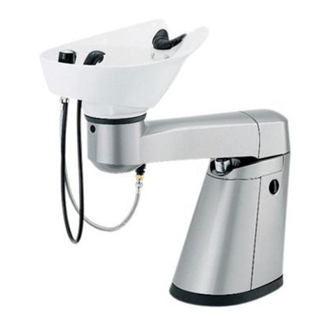
Takara Belmont RS III User manual

Other manuals for RS III

2

Other Takara Belmont Plumbing Product manuals

Takara Belmont KAZE AY-KFPLU AY-NRS1 User manual

Takara Belmont

Takara Belmont KAZE AY-KFPLU AY-NRS1 User manual

Takara Belmont Swash User manual

Takara Belmont

Takara Belmont Swash User manual

Takara Belmont RS SWING User manual

Takara Belmont

Takara Belmont RS SWING User manual

Takara Belmont MAJOLICA PORTO EX-SB 1 Series User manual

Takara Belmont

Takara Belmont MAJOLICA PORTO EX-SB 1 Series User manual

Popular Plumbing Product manuals by other brands

Moen SANI-STREAM 8797 manual

Moen

Moen SANI-STREAM 8797 manual

Grohe Allure Brilliant 19 784 manual

Grohe

Grohe Allure Brilliant 19 784 manual

Cistermiser Easyflush EVO 1.5 manual

Cistermiser

Cistermiser Easyflush EVO 1.5 manual

Kohler Triton Rite-Temp K-T6910-2A installation guide

Kohler

Kohler Triton Rite-Temp K-T6910-2A installation guide

BEMIS FNOTAB100 Installation instruction

BEMIS

BEMIS FNOTAB100 Installation instruction

Hans Grohe ShowerTablet Select 700 13184000 Instructions for use/assembly instructions

Hans Grohe

Hans Grohe ShowerTablet Select 700 13184000 Instructions for use/assembly instructions

Akw Stone Wash Basin Installation instructions manual

Akw

Akw Stone Wash Basin Installation instructions manual

Enlighten Sauna Rustic-4 user manual

Enlighten Sauna

Enlighten Sauna Rustic-4 user manual

Moen ShowHouse S244 Series quick start guide

Moen

Moen ShowHouse S244 Series quick start guide

Sanela SLWN 08 Mounting instructions

Sanela

Sanela SLWN 08 Mounting instructions

Franke 7612982239618 operating instructions

Franke

Franke 7612982239618 operating instructions

Heritage Bathrooms Granley Deco PGDW02 Fitting Instructions & Contents List

Heritage Bathrooms

Heritage Bathrooms Granley Deco PGDW02 Fitting Instructions & Contents List

Tres TOUCH-TRES 1.61.445 instructions

Tres

Tres TOUCH-TRES 1.61.445 instructions

STIEBEL ELTRON WS-1 Operation and installation

STIEBEL ELTRON

STIEBEL ELTRON WS-1 Operation and installation

Miomare HG00383A manual

Miomare

Miomare HG00383A manual

BELLOSTA revivre 6521/CR1 quick start guide

BELLOSTA

BELLOSTA revivre 6521/CR1 quick start guide

American Standard Heritage Amarilis 7298.229 parts list

American Standard

American Standard Heritage Amarilis 7298.229 parts list

BorMann Elite BTW5024 quick start guide

BorMann

BorMann Elite BTW5024 quick start guide

manuals.online logo
manuals.online logoBrands
  • About & Mission
  • Contact us
  • Privacy Policy
  • Terms and Conditions

Copyright 2025 Manuals.Online. All Rights Reserved.

RSⅢAbove the floor plumbing Installation Instructions
ż3OXPELQJNLW
 ($563>56Ⅲ$ERYHWKHIORRUSOXPELQJNLW@
ż3OXPELQJFRYHU
($(63&>(632,5$ERYHWKHIORRUSOXPELQJFRYHU&@
Ŷ2YHUDOOOD\RXW
Ɣ7RSYLHZ Ɣ6LGHYLHZ
$VIRUWKHGLPHQVLRQRI56Ⅲ, refer to “RSⅢInstallation Instructions”.
150
611
822
900
(632,5$ERYHWKHIORRUSOXPELQJFRYHU&NLW
0DLQWHQDQFHFRYHUIL[LQJEUDFNHW
Maintenance cover attachment
plate
Maintenance cover (cut)
&XWZKHQXVH
Ŷ&RQWHQWRISDFNDJLQJ
・)L[LQJVFUHZVIRUSOXPELQJFRYHU
<80((632,5$ERYHWKHIORRUSOXPELQJ2SHUDWLQJ0DQXDO1RXVH
<80((632,5$ERYHWKHIORRUSOXPELQJ,QVWDOODWLRQ,QVWUXFWLRQV1RXVH
150
160
900
Ver. 1 2012.8
㸯
)ORRUIL[LQJVFUHZSFV
(632,5$ERYHWKHIORRUSOXPELQJFRYHU&
RSⅢ$ERYHWKHIORRUSOXPELQJ2SHUDWLQJ0DQXDO
RSⅢAbove the floor plumbing Installation Instructions
5XEEHUSDFNLQJ
)L[LQJVFUHZVHWIRUNLW
*ABS resin
(632,5$ERYHWKHIORRU
SOXPELQJFRYHU&
Maintenance cover
Maintenance cover
(632,5$ERYHWKHIORRU
SOXPELQJFRYHU&
7KLVPDQXDOLVDQDGGLWLRQDOPDQXDOWRXVHIRULQVWDOOLQJ56ⅢXVLQJDQDERYHWKHIORRUSOXPELQJV\VWHP
For the installation of RSⅢmain unit, please refer to “RSⅢInstallation Instructions”.
RSⅢ$ERYHWKHIORRUSOXPELQJNLW
6WRSYDOYHZLWKVLQJOHVLGH
nut, 2 pcs.)
Ŷ3OXPELQJOD\RXW
Ɣ7RSYLHZ Ɣ)URQWYLHZVHHLQJIURPERZOVLGH
Ŷ$WWDFKPHQWSRVLWLRQRIWKHIORRUIL[LQJEUDFNHW
Ŷ%HIRUHLQVWDOODWLRQ
&XWRIIWKHSOXPELQJFRYHUDVVKRZQEHORZ
 7KHUHDUHQRIURQWDQGEDFNVLGH
3ODFHPDLQWHQDQFHFRYHUDWWDFKPHQWSODWH
RQWKHSOXPELQJFRYHUDVVKRZQLQWKHULJKW
LOOXVWUDWLRQ
 (7DSSLQJVFUHZDQGIODWZDVKHU)
Ɣ3UHSDUHWKHSOXPELQJFRYHU
0DLQWHQDQFHFRYHU
DWWDFKPHQWSODWH
)ODWZDVKHU
7DSSLQJVFUHZ
65
78
64 4343

&XWWKHUDLVHGSOXPELQJSDFNLQJSURYLGHGZLWKWKHPDLQXQLW
LQFPZLGWKDQGVWLFNRQWKHSRVLWLRQDVVKRZQLQWKHULJKWLOOXVWUDWLRQ 3LSHSDFNLQJ
 350
350

凚0DLQIUDPHIL[LQJSRVLWLRQ
55
8



900
405
755
$ERYHWKHIORRUSOXPELQJFRYHU&
0DLQIUDPH
(QWLUHSLSHFDQQRWEHFRYHUHGLIWKHSOXPELQJOHQJWKWLVRUPRUH
,IWKHSLSHOHQJWKLVVKRUWHUWKDQFXWWKHSOXPELQJFRYHUDQGXVH
'RXEOHVLGHGWDSHLVRULJLQDOO\DSSOLHGWRWKHSLSHSDFNLQJ
㸰
 35

凚+HLJKWRIERZOVLGH
30
50
䯲
80
凚+HLJKWDWZDOOVLGH
'UDLQSLSH
:DWHUVXSSO\SLSH
+RWZDWHU
VXSSO\SLSH
(632,5$ERYHWKHIORRU
SOXPELQJFRYHU&
$ERYHWKHIORRU
SOXPELQJFRYHUFHQWHU
'UDLQSLSH
9893
+RWZDWHUVXSSO\SLSH
PP
*PDOHVFUHZ
:DWHUVXSSO\SLSH
PP
*PDOHVFUHZ
$ERYHWKHIORRU
SOXPELQJFRYHUFHQWHU
7KHDERYHLOOXVWUDWLRQVKRZVZKHQWKHJUDGLHQWLV
(QVXUHWKDWWKHGUDLQSLSHLVLQVWDOOHGDWDJUDGLHQWRIRUPRUHIRU
DGLDPHWHURIOHVVWKDQijRURUPRUHIRUDGLDPHWHURIijRUPRUH
ƔPrepare the maintenance cover.
(1) Attach the maintenance cover fixing bracket
to the maintenance cover.
 ( flat washer M4 x 10, cap washer, cap cover)
When attaching the maintenance cover fixing bracket,
fix it at the bottom edge of the oval hole of the maintenance
cover.
㸱
Cap cover
Cap washer
Flat screw
Maintenance cover
fixing bracket
(1) Referring to the “Attachment position of the floor fixing bracket”, temporarily place the floor fixing bracket on the
floor. The temporarily placed position of the floor fixing bracket should be based on the base center and the base
edge.
(2) Fix the floor fixing bracket with screws.
If in case of a mortar floor, use anchor bolts.
 (5 x 30 tapping screw, 2 pcs.)
Ŷ,QVWDOODWLRQPHWKRGRIDERYHWKHIORRUSOXPELQJ
(3) Install the water, hot water supply pipe, and drain pipe on floor.
 Refer to the “Plumbing layout” for the installation position.
After temporarily placing the floor fixing bracket on the floor, be sure to attach the plumbing
cover C and the maintenance cover (cut), and check and confirm the fixing position.
CAUTION
*If in case you will cut the length of the plumbing cover C, the number of the floor fixing
bracket used would change accordingly.
(4) Joint the drain pipe and the raised drain pipe as shown in the
right illustration. Be sure to insert the drain hose packing to
the raised drain pipe thoroughly.
(5) Attach blade flexible pipe and stop valve as shown
in the right illustration.
* The knob of the water stop valve should be facing opposite
side of the chair unit.
Drain hose packing (attached to main unit)
Drain hose fixing clamp (attached to main unit)
Drain hose
Raised drain pipe
[Hot water][Water]
Filtered check valve
Flexible pipe (accessory of
the RSⅢbasin unit)
Packing (accessory of
above the floor plumbing kit)
Stop valve (with single nut, accessory
of above the floor plumbing kit)
Packing (accessory of above
the floor plumbing kit)
・Check and confirm if there is no bend or damage on the drain hose. Failure to follow
this instruction may cause bad flow of drain or breakage of the drain hose.
・Make sure if the drain hose clamp is attached firmly. If it is not attached firmly,
this may cause water leakage and drain hose may come loose.
CAUTION
(6) After the plumbing work is finished, refer to “2. Piping
(3. Test water flow, Cleaning)” of the “RSⅢInstallation Instructions”.
(7) Cut the plumbing cover C based on the installation position of the basin unit.
Floor fixing bracket
* The black caps are provided for covering the screw heads.
Follow to the instructions shown in the "How to adjust faulty temperature
regulation (Page 10)" shown in the "RSIII Installation Instructions".
* When attaching the reducing valve, make sure that the position
of filter should be higher than original position. The plumbing cover
prevents stop valve from opening and closing smoothly.
* To attach reducing valve smoothly, remove the front cover to
detach the flexible pipe between thermostat and filter.
* Be sure to do this process. Failure to follow this instruction may cause water leakage inside of the plumbing cover leading to corrosion of the
plumbing cover and floor.
* The screw holes of the plumbing cover C are oval holes to allow minor adjustment
of the fixing position.
* The screw holes of the floor fixing brackets are made larger than the fixing screws
to allow minor adjustment of the fixing position.
(11) Install the maintenance cover (cut) referring to “4. Attach cover (2. Mounting the Maintenance Cover (Page 16))” of
the “RS III Installation Instructions”.
  Then, continue the installation after the process “After installation (Page 24, 25)”.
(8) Place the plumbing cover C over the floor fixing bracket, and check the below points.
 1. Check and make sure that there is no large clarance at the jointed parts of the plumbing cover C.
2. Check and make sure that the plumbing cover C could be fixed correctly to the floor fixing bracket with screws.
(9) After checking the installation work, fix the plumbing cover C with screws.
(SFVRI0[VFUHZVDQGSFVRIZDVKHUijSHURQHIORRUIL[LQJEUDFNHW
  After screwing is finished, cover the screw head with the black caps provided with the screws.
(10) Apply caulking materials to any gaps between the plumbing cover C and floor.
1E01K4A0
7.2 ㎜
Hole
Depth
30㎜
(1) Drill open a hole of the
specified diameter and
depth.
(2) Remove the dust from each
anchor hole by cleaning with
a vacuum cleaner.
ĺ
(4)Attach the floor fixing bracket
and fasten the tapping screw
using a screwdriver.
(3)Insert the anchor bolt lightly
in the hole. 
Installing screws
(In the case of fixing the floor fixing bracket to mortar floor.)
Floor fixing bracket
Floor
If in case the plumbing cover C can not be fixed correctly, check and correct the “Attachment position of the floor
fixing bracket”.
㸲
Reducing valve
(Sold separately)
Filtered check
valve
Front
cover
Stop valve
How to adjust faulty temperature regulation
* The black caps are provided for covering the screw heads.
Follow to the instructions shown in the "How to adjust faulty temperature
regulation (Page 10)" shown in the "RSIII Installation Instructions".
* When attaching the reducing valve, make sure that the position
of filter should be higher than original position. The plumbing cover
prevents stop valve from opening and closing smoothly.
* To attach reducing valve smoothly, remove the front cover to
detach the flexible pipe between thermostat and filter.
* Be sure to do this process. Failure to follow this instruction may cause water leakage inside of the plumbing cover leading to corrosion of the
plumbing cover and floor.
* The screw holes of the plumbing cover C are oval holes to allow minor adjustment
of the fixing position.
* The screw holes of the floor fixing brackets are made larger than the fixing screws
to allow minor adjustment of the fixing position.
(11) Install the maintenance cover (cut) referring to “4. Attach cover (2. Mounting the Maintenance Cover (Page 16))” of
the “RS III Installation Instructions”.
  Then, continue the installation after the process “After installation (Page 24, 25)”.
(8) Place the plumbing cover C over the floor fixing bracket, and check the below points.
 1. Check and make sure that there is no large clarance at the jointed parts of the plumbing cover C.
2. Check and make sure that the plumbing cover C could be fixed correctly to the floor fixing bracket with screws.
(9) After checking the installation work, fix the plumbing cover C with screws.
(SFVRI0[VFUHZVDQGSFVRIZDVKHUijSHURQHIORRUIL[LQJEUDFNHW
  After screwing is finished, cover the screw head with the black caps provided with the screws.
(10) Apply caulking materials to any gaps between the plumbing cover C and floor.
1E01K4A0
7.2 ㎜
Hole
Depth
30㎜
(1) Drill open a hole of the
specified diameter and
depth.
(2) Remove the dust from each
anchor hole by cleaning with
a vacuum cleaner.
ĺ
(4)Attach the floor fixing bracket
and fasten the tapping screw
using a screwdriver.
(3)Insert the anchor bolt lightly
in the hole. 
Installing screws
(In the case of fixing the floor fixing bracket to mortar floor.)
Floor fixing bracket
Floor
If in case the plumbing cover C can not be fixed correctly, check and correct the “Attachment position of the floor
fixing bracket”.
㸲
Reducing valve
(Sold separately)
Filtered check
valve
Front
cover
Stop valve
How to adjust faulty temperature regulation