DE
4
01 Allgemeines
Alle Whirlwannen werden auf einem selbsttragenden,
höhenverstellbaren Untergestell geliefert.
Die Systemkomponenten (Whirlpumpe, Steuerung und Gebläse)
sind gemäß beiliegender Maßzeichnung angeordnet.
Bei Modellen, die werksseitig eine Wahlmöglichkeit zwischen
„Rechts- oder Linksausführung“ bieten, wird standardmäßig
„Rechtsausführung“ geliefert (immer vom Standpunkt außen vor
der Ab-/Überlaufarmatur betrachtet).
Zu beachten:
■Lieferung auf Vollständigkeit und Beschädigungen
überprüfen.
■Für Schäden durch Transport- oder Zwischenlagerung
kann keine Haftung übernommen werden.
■Wanne nicht am vorinstallierten Rohrsystem anheben!
Jegliches Anstoßen vermeiden!
■Wannenoberfläche und gefährdete System-
Komponenten bei der Installation durch Abdeckung vor
Beschädigungen bzw. übermäßiger Verschmutzung
schützen.
■Die einzelnen System-Kompenenten müssen für
spätere Wartungsarbeiten frei zugänglich bleiben!
Personen mit verschiedenen Krankheiten wie z.B. akute
Infektionen, Gerinnsel, Nierenversagen, Herzkrankheiten,
Diabetes sollten das Whirlsystem erst nach einer Artztberatung
benutzen, was ermöglicht die Anwendung einer entsprechenden
Therapie.
Eine ärtzliche Beratung empfehlen wir ebenso schwangeren
Frauen.
Da die Hydromassage für die Kinder erschöpfend ist, sollen sie
nicht unbeaufsichtigt in solch einem Bad gelassen werden.
Die vorhandene Einrichtung ist für das Benutzen von Personen
(auch Kinder) mit eingeschränkten körperlichen, sensorischen
oder psychischen Fähigkeiten oder Personen, die das Whirlsystem
nicht benutzt haben bzw. mit der Anlage nicht vertraut sind,
nicht geeignet. Ausgenommen sind Situationen, in denen es
unter Aufsicht oder gem. der Bedienungsanweisung durch eine
verantwortungsberechtigte Person stattfindet.
Man man muss auf die Kinder achten, dass sie keinen Zutriff zur
Anlage haben.)
Ältere Menschen, die sich langsam bewegen oder behinderte
Personen, sollten die Badewannen vorsichtig benutzen.
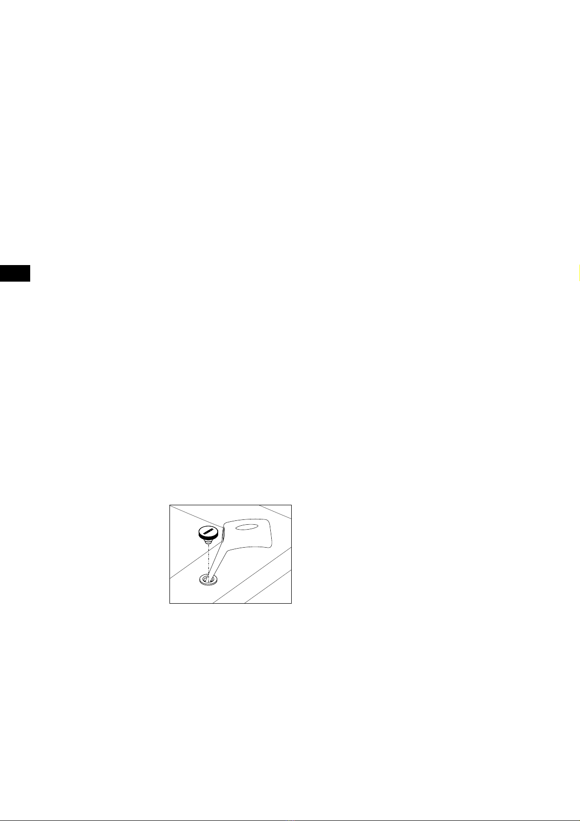
02 Aufstellung/Montage
Wanne aufstellen und mittels der
höhenverstellbaren Kunststoff-Gestellfüße
waagerecht ausrichten.
Fuß mit flacher Kontermutter sichern.
Zur Schalldämmung (Vermeidung von
Körperschallbrücken zur Wand) ein
handelsübliches Wandanschlussprofil
verwenden.
Bei Modellen, die für eine
Wandanbindung vorgesehen sind, ist
eine Wannenrandauflage erforderlich
(erforderliches Zubehör: Wannenanker, gemäß der dort
beiliegenden Montageanweisung montieren).
Bei der Montage darauf achten, dass die Verkleidung den
Wannenrand unterstützt!
02.01 „Combi-Plus“ (Sonderzubehör)
(Wanneneinlauf mit Spezial Ab-/Überlaufarmatur)
Für die Montage ist ein zusätzlicher Rohrunterbrecher erforderlich.
Der Wasseranschluss ist gemäß der dort beiliegenden
Montageanweisung durchzuführen.
02.02 Wasserinstallation
Die Wasser- und Abwasserinstallation ist jeweils nach den
örtlichen Vorschriften durchzuführen.
Beim Anschluss an die Trinkwasserinstallation muss bauseitig
oder vom Anwender eine den nationalen Anforderungen
entsprechende Sicherungseinrichtung vorgeschaltet werden.
02.03 Elektro-Installation
Whirlwannen sind für den privaten Hausgebrauch und
Hotels ausgelegt und entsprechen den einschlägigen DIN/
EN-Vorschriften. Ausgenommen ist eine Verwendung im
medizinischen Bereich.
⚠
Hinweis:
Sämtliche Elektro-Arbeiten müssen durch
Fachelektriker gem. der geltenden DIN/EN,
typischen Landesvorschriften und örtlichen
Stromvorschriften durchgeführt werden!
Das Whirlwannen-System ist ausgelegt für eine
Wechselspannung 230 V~AC, 50/60 Hz, 2kW. Die Whirlanlage
ist durch eine separate Stromkreiszuleitung elektrisch zu
versorgen und entsprechend der Nennleistungsaufnahme
mit 10 A abzusichern, gemäß dem Typenschild. Weitere
Verbraucher dürfen nicht abgezweigt werden. Gemäß den
geltenden Bestimmungen müssen Whirlpoolbäder als
elektrische Geräte der Klasse I ständig über einen zweipoligen
Trennschalter an das elektrische System angeschlossen
werden. Aus Sicherheitsgründen darf der Anschluss des
Badewannenanschlusskabels an das Stromnetz nur mit einem
elektrischen Anschlussstecker erfolgen, der durch einen
Überstromausschalter und einen Differentialschutzschalter
(RCD-Gerät) mit einer nominellen Spannung von 30 mA gesichert
ist. Dadurch wird an allen Polen die Installation vom Stromnetz
getrennt, wobei die Kontakte mindestens 3 mm weit geöffnet sein
müssen. Das RCD-Gerät muss mindestens einmal monatlich
überprüft werden. Es wird empfohlen, bei Nichtbenutzung
des Whirlsystems die Verbindung der Whirlanlage zum
Stromnetz durch den Haupt-/FI-Schalter zu unterbrechen. Der
Mindestquerschnitt des Badewannenanschlusskabels beträgt
3 x 1,5 mm² (Länge L = 1,8 m). Bei Badewannen, die mit einem
E-Heizer (2kW) ausgerüstet sind, sollte ein Anschlusskabel mit
einem Querschnitt von 3 x 2,5 mm² (Länge L = 2,0 m) verwendet
werden. Ein fester Stromanschluss der Badewanne sollte in Zone
I vorbereitet werden (die Einheit befindet sich unter der Wanne).
Außerdem sollte ein Ausgleichsanschluss zur Verfügung stehen.
Eine markierte Klemmvorrichtung wird an der Badewanne
angebracht, an die ein Ausgleichskabel angeschlossen werden
sollte 4mm².
Der bauseitige Anschluss hat über die fest zu installierende
Feuchtraumverteilerdose (IP 65, mindestens 30 cm über dem
Fußboden im Bereich unter der Wanne) zu erfolgen. Bei der
Installation einer Badewanne ist auf die Teile zu achten, die aktive
Elemente beinhalten (mit Ausnahme von Elementen mit einer
sicheren Niedrigspannung, d. h. mit einer maximalen Spannung
von 12 V), da diese für Personen, die sich in der Badewanne
befinden, nicht zugänglich sein dürfen.
Der Umstand, dass die Badewanne einen Stromanschluss besitzt,
muss in der Garantiekarte mit der Unterschrift und dem Stempel
der autorisierten Person vermerkt werden. Die Karte dient als
Nachweis der Gültigkeit der Garantie.