Talent LP64LED-FLAT User manual

TABLE OF CONTENTS
1. Safety Instructions
2. Technical Specifications
3. Installation
4. How to Connect the Fixture
5. D X512 Connections
6. How to Set the Unit
7. D X Configuration
8. IR Remote Control
9. Troubleshooting
10. D X General Information

1. Safety Instructions
• Please keep this User anual for future consultation. If you sell the
fixture, be sure to include this instruction booklet to ensure proper
maintenance and use.
• Unpack and check carefully for transportation damage before using the
fixture.
• Before operating, ensure that the power supply voltage and frequency
match the power of your electrical system.
• It's important to connect the yellow/green conductor to ground to avoid
electric shock.
• Disconnect main power before servicing and maintenance.
• Use a safety cable when permanently mounting this fixture. Always
handle the fixture with care.
• aximum ambient temperature is 104° F.
• In the event of a serious operating problem, stop using the fixture
immediately. Please contact the dealer from whom you purchased the
fixture, the nearest authorized technical repair facility, or Talent Sound &
Lighting directly.
• Do not connect the device to any dimmer pack.
• Do not touch exposed wires during use, as there might be a hazard of
electrical shock.
• To prevent or reduce the risk of electrical shock or fire, do not expose
the fixture to rain or moisture.
• The fixture must be replaced if there is visible damage to the housing.
• Do not look directly at the LED light beam while the fixture is on.
Warning: Please read the instructions carefully. They include important
information about installation, operation, and maintenance. Do not
connect more than 32 units in series (daisy-chaining) on a single power
circuit.
Caution: There are no user serviceable parts inside the fixture. Do not
open the housing or attempt any repairs yourself. In the unlikely situation
your unit may require service, please contact your dealer or Talent Sound
& Lighting.
2. Technical Specifications
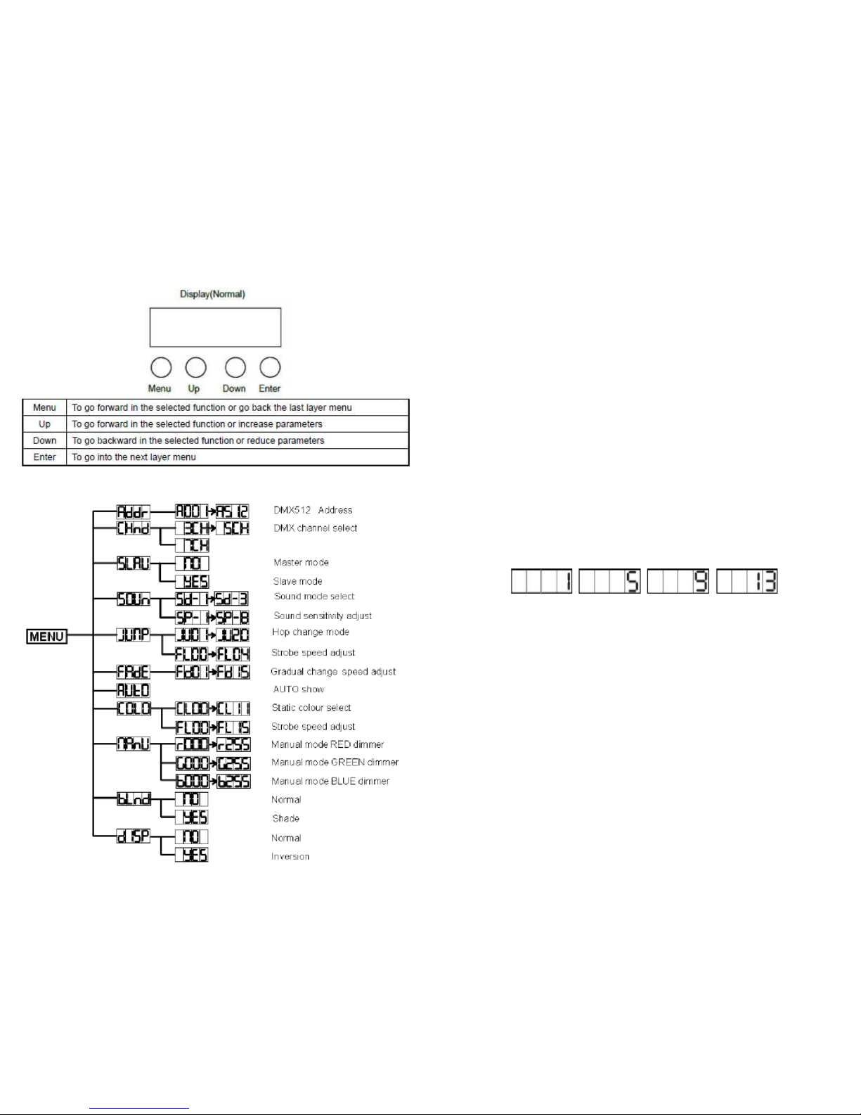
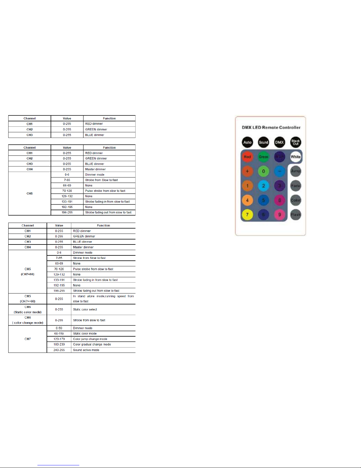
• D X channels: 3/5/7 selectable via digital display
• 181 Ultra Bright 10 mm LEDs (Red: 49, Green: 72, Blue: 60)
• 125 Static Colors/Dimmer/Strobe/Fade/Jump
• Auto, sound active, D X, and master/slave modes
• Internal programs with sound activation
• 3-pin XLR in/out sockets for D X control
• RGB color mixing
• Beam angle: ±20°
• Power consumption: 20 watts
Power input: AC 90V-250V, 50-60 Hz
• Dimension: 10.83" diameter x 4.13" deep
• Weight: 3.52 lbs.

3. Installation
The unit should be mounted via its screw holes on its bracket. Always
ensure that the unit is installed to avoid vibration while operating. Always
ensure that the structure to which you are attaching the unit is secure and
is able to support a weight of 10x this fixture's weight (35.2 lbs.) Always
use a safety cable that can hold 12x the weight of the fixture.
. How to Connect the Fixture
3-Pin and 5-Pin XLR DMX Connectors:
Some manufactures use 5-pin XLR connectors for data transmission in
place of 3-pin. 5-pin XLR fixtures may be implemented in a 3-pin XLR
D X line. When inserting standard 5-pin XLR connectors into a 3-pin
line, a cable adapter must be used. The chart below details the correct
cable conversion.
5. DMX512 Connections
D X512 is a widely used protocol for intelligent lighting control, with
512 available channels. Even if you do not wish to operate your Talent
lighting fixture via an outboard D X controller, utilizing the master/slave
mode will still require unit-to-unit connection by proper D X cables.
Caution: Common microphone cables may be used to connect small
numbers of D X fixtures over short distances, but offer the risk of erratic
operation. Use of correct D X cables greatly reduces data errors caused
by improper connection.
• If you are using a controller with 5-pin D X output, use a 5-pin to 3-pin
adapter cable.
• Connect fixtures together in a "daisy chain" by connecting the D X
output of the first fixture to the D X input of the next fixture. This cable
cannot be branched or split by a "Y" cable. Inadequate or damaged cables,
bad solder joints, or corroded connectors can easily distort the signal,
cause errors, and shut down the system. Never allow contact between the
data common/shield connection (XLR Pin 1) and the fixture's
chassis/electrical ground.
• The D X output and input connectors are pass-through to maintain the
D X circuit if power to one of the units is disconnected.
• On the last fixture, the D X output should be terminated with a
terminator to reduce signal errors. Solder a 120 ohm 1/4 watt resistor
between pin 2 (D X-) and pin 3 (D X+) on a 3-pin XLR plug and
connect it to the D X output of the last fixture.

6. How to Set the Unit
6.1 Control Panel
6.2 Main Function
Your Talent Sound & Lighting fixture may be operated as a stand-alone
device that runs on pre-programmed routines or sound activation, in
master/slave mode with other devices, or via an external D X512
controller. In D X mode it is configurable to be controlled by 3, 5, or 7
channels.
Besides stand-alone operation, there are two main ways to control the
fixture:
A. Universal D X control mode
B. aster/Slave operation
A. Universal DMX controller
This fixture's D X address can be set remotely by a universal D X
controller. First, you need to program two scenes into a chase, and then
link the fixtures to the universal D X controller. When you run the chase,
the fixtures in the chain will set the series D X address automatically.
Each lighting fixture needs to have an address set when in D X mode, to
receive the data sent by the controller. The address number is between 0-
511 (usually 0 & 1 are equal to 1). Please refer to the following diagram to
set the address for the first four units.
The numbers 1, 5, 9, and 13 indicate the starting address of each of the
fixtures.
B. Master/Slave operation
The fixture allows you to link as many as 16 fixtures together and operate
without a controller. In aster/Slave mode, the first fixture will control
the others to give an automatic, sound activated, synchronized light show.
This function is good for when you want an instant performance. The first,
or master, fixture's D X input will have nothing connected to it. Its
output connects to the slave fixtures, which will be set in slave mode
automatically.

7. DMX512 Configuration
DMX Channel Values (3-Channel Mode)
DMX Channel Values (5-Channel Mode)
DMX Channel Values (7 Channel Mode)
For additional details about D X operation, please review Section 10.
8. IR Remote Control
8.1 IR Remote Control Keypad

8.2 IR Remote Control Functions
9. Troubleshooting
Here are some troubleshooting suggestions:
A. The fixture does not work, there is no light output.
1.) Check the connection of power and main fuse.
2.) easure the voltage output on your power receptacle to ensure proper
voltage.
B. Fixture does not respond to D X control.
1.) D X LED should be on. If not, check D X connectors and cables for
proper connection.
2.) If D X LED is on but not responding to a channel, check the D X
address settings and D X polarity.
3.) If you have intermittent D X signal problems, check the pins on the
cable connectors and on the fixture.
4.) Try to use a different D X controller.
5.) Interference may occur if D X cables are run alongside high voltage
cables.
C. Fixture responds erratically to D X control.
1.) You may have a break in the D X cabling. Check the LED for the
response of the master/ slave mode signal.
2.) Wrong D X address in the fixture. Set the fixture to the proper
address.
3.) Use of microphone cables for D X connections can cause errors
D. The fixture doesn't respond to sound.
1.) ake sure the fixture is not set to receive a D X signal.
2.) Check the fixture's internal microphone by tapping the microphone.

10. DMX General Information
The D X512 digital communication protocol was introduced to control
stage lighting and special effects.
The D X standard features 512 available channels, and they are
assignable in any sequence that conforms to the user's needs. Each D X-
capable fixture requires one or more sequential channels. A starting
address, which indicates the first control channel reserved for that
particular fixture, must be assigned to the fixture before the controller can
recognize it. D X controllable fixtures may vary in the number of
channels they require, depending on the fixtures features and/or
functionality.
Channels should never be permitted to overlap; otherwise, for example, a
fader that controls blue output on one fixture may cause strobing or
dimming on an adjacent, incorrectly assigned fixture. ultiple fixtures of
the same type that use an identical starting address will function in unison.
Fixtures assigned properly spaced starting addresses will operate
individually, but a D X controller with sufficient channels can be
configured to run these same fixtures either combined or independently.
The sequence in which D X fixtures are connected has no effect on how
a controller communicates with each individual lighting fixture. Although
3-pin XLR mic cables may be used to connect D X fixtures over short
runs, longer distances will introduce data errors due to the mic cable's
incorrect impedance. For best results, Talent Sound & Lighting
recommends the use of correct 120 ohm, low-capacitance, twisted pair
cable designed for the D X512 protocol. It is also suggested that a
termination resistor plug be used on the output connector of the last fixture
in an array of D X instruments. This resistance ensures proper data
transmission.
Notes
Table of contents
Popular Lighting Equipment manuals by other brands

JUST NORMLICHT
JUST NORMLICHT DLS COLOR VIEWING LIGHT V7 L Assembly and instruction manual

Velleman
Velleman HQ Power XML1 user manual

CEAG
CEAG 58011 CGLine Mounting and operating instructions

Chauvet Professional
Chauvet Professional STRIKE ARRAY 4 Quick reference guide

SLC
SLC PRO PAR Quad 5 user manual

YORKVILLE
YORKVILLE LP-LED4 Service manual

RAB
RAB SHARK - 8FT instructions

Whelen Engineering Company
Whelen Engineering Company Edge 10000 installation guide

Feeney
Feeney Feeney DesignRail 24V LED Lighting V2, installation instructions

Beamz professional
Beamz professional BAC508 Aluminium ProPar instruction manual

lightculture
lightculture NEON MICRO Y installation guide

Light Emotion
Light Emotion UVLED User instructions