TALITOR(FAR EAST) CO. 30450712 User manual

USER’S MANUAL
Version : 051223
Model 30450712
MPEG-4 Hi-Resolution Real-time Triplex DVR
8Channels

30450712 MPEG-4 Hi-Resolution DVR
1
Table Of Contents
Important Notice ........................................................................................................2
Operation precautions..................................................................................................3
Chapter 1 Product Features and Specifications..................................................................4
1.1 Technical Specifications.................................................................................4
1.2 Product Features..........................................................................................5
Chapter 2 Installation...................................................................................................7
2.1 Hard Disk Installation......................................................................................7
2.2 Front Panel Introduction...................................................................................8
2.3 Remote Controller...........................................................................................9
2.4 Back Panel Introduction ...................................................................................10
Chapter 3 System Operation .........................................................................................12
3.1 Turn on/off the recorder.................................................................................12
3.2 Recording operation.......................................................................................12
3.3 Alarm connection operation.............................................................................13
3.4 Pan-Tilt-Zoom control operation.......................................................................13
3.5 Network connection operation.........................................................................13
Chapter 4 Front Panel And Remote Controller Operation.....................................................14
4.1 Operation Menu Introduction...........................................................................14
4.2 Menu Operation............................................................................................19
4.3 Main Menu Operation.....................................................................................22
Chapter 5 Operation Over Network.................................................................................30
5.1 Setting on the client end................................................................................30
5.2 Login and Logout ..........................................................................................30
5.3 Operation of the right key menu......................................................................31
5.4 Operation of the Records Search......................................................................33
5.5 Operation of the Config .................................................................................35
5.6 Operation of the Assistant ..............................................................................39
Chapter 6 Serial port Operation .....................................................................................42
6.1 System setting of the Mini Terminal..................................................................42
6.2 Serial port upgrading operation .......................................................................42
Chapter 7 Frequent Questions and Answers.....................................................................43
Appendix...................................................................................................................45
A.Operation of DVR with Speed Dome............................................................................45

MPEG-4 Hi-Resolution Digital Video Recorder
2
Important Notice
1. Power supply
This DVR uses a 110V/230V AC switching type power supply input, please check carefully the voltage switch
is properly set to fit your power source before you power ON this DVR.
2. Hard Disk
This DVR will only start after HDD is properly installed.
Please install at least one HDD (Maxtor is the only recommended).
HDD capacity can be 80GB up to 300GB.
3. CD-RW
A SONY CD-RW model 230A (IDE type) is recommended for the D1 DVR, or
A BenQ model 5232WI (USB type) is recommended for the D1 DVR.
For DVR CIF resolution models, a SONY DVD-RW model 710A is also supported.
4. Operating this DVR
Press ENTER key or click USB mouse once, for entering password.
The default password is 888888, for initially entering this DVR.
DVR : D1 resolution DVR
# 3045076 –4CH (2CIF –640 x 240) # 30450711 –4CH
# 3045077 –8CH (2CIF –640 x 240) # 30450712 –8CH
# 3045078 –16CH (CIF –320 x 240)
Can be switched from 230V / 115V
Power ON/OFF switch

30450712 MPEG-4 Hi-Resolution DVR
3
Operation precautions
All the safety and operating instructions should be read before the appliance is operated The improper
operation may cause irreparable damage to the appliance.
1Installation condition
1.1 Put away from extreme hot places and humid places
1.2 Avoid direct sunlight
1.3 Be horizontally installed
1.4 Avoid violent vibrating, lefts and place gently
1.5 Do not place other devices upon
1.6 Put in well ventilation places, not block the radiator fan in the back of the recorder
2Installation and operation precautions
2.1 Please check the main power switch and voltage of power supply to avoid voltage mismatch attach the
power cable to the unit and connect it to your local mains supply, then open the power
2.2 At the first use, assure the installation of hard disk and the master-slave jumper wire should be set.
MAXTOR hard disk is strongly recommend
2.3 Do not unplug the power connector before turn the power off correctly and switch the power on & off
within short period
2.4 Unauthorized repair or pats substitutions may result in fire, electric shock or other hazards
2.5 do not attempt to service this equipment by yourself refer all servicing to qualified service personnel
3Open cabinet and check inventory
Check the items supplied against the list below after open the case
3.1 One power Cord x 1
3.2 Ethernet cable (positive cable) x 1
3.3 One serial port cable x 1
3.4 User manual x 1
3.5 CD-ROM for installation x 1
3.6 One 25-pin alarm converter x 1

MPEG-4 Hi-Resolution Digital Video Recorder
4
Chapter 1 Product Features and Specifications
1.1 Technical Specifications
Parameter 30450712 –8Channel
Processor High performance embedded microprocessor
Operation system Embedded Linux Operation System
Interface GUI, Mouse support, menu color changeable
Video input 8composite video input (NTSC/PAL) BNC, (10Vp-p. 75O)
Video output 1 PAL/NTSC composite video output, BNC(10Vp-p. 75O), 1 VGA monitor
output
Audio input 8Channel 1200~2800mv30KO (BNC)
Audio Output 1 Channel 3500mv 3KO (BNC)
Screen division 1, 4, 9 display
Video format NTSC (525 line, 60f/s), PAL (625 line, 50f/s)
System resource Real-time recording, one channel playback and network operation
simultaneous (Triplex)
Image resolution
NTSC/PAL Real-time monitor D1 720x480/704x576
NTSC/PAL Playback D1 704 x 480/704x576
NTSC/PAL Half-D1 360x480/352x576
NTSC/PAL DCIF 720x240 /704x288
NTSC/PAL CIF 360x240 / 352x288
Motion detection Area setting 192 (16x12) areas setup for each channel; detection sense
setting : Multiple levels detection sense
Video compression MPEG-4 , H.264
Audio compression PCM
Video recording speed Real-time mode : NTSC –1fps ~30fps for each channel adjustable
PAL –1fps ~ 25fps for each channel adjustable
Image quality 6 levels selectable
Hard disk Inside equipped 4 IDE ports, able to install 8 HDDs inside
HDD space used Audio : PCM 28.8Mbyte/Hour Video : 40 ~ 2000Mbyte/hour
Alarm input 4 channel voltage alarm input (+5V ~ +15VDC. Needed for the alarm input)
Alarm output 3 channel output ( 2 NO contact, 1 controllable + 12V output)
Alarm relay 30VDC 1A, 125VAC 0.5A-relay output
Network connection RJ45 10M/100M Ethernet connection
Pan-Tilt control RS-485, RS-232
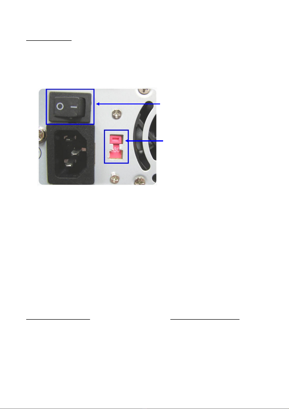
Power supply 115V / 230V 47/63Hz
Power consume 40W (without HDD)
Working temperature -10℃~ + 55℃
Working humidity 10% ~ 90%
Barometric pressure 86kpa ~ 106kpa
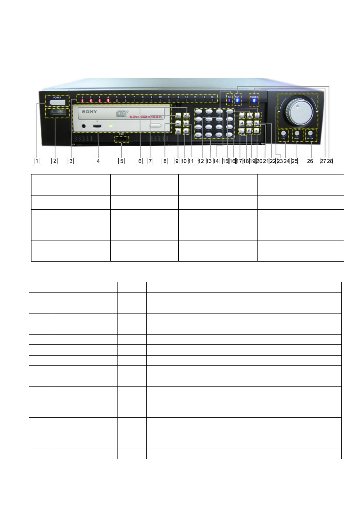
Dimension 2U standard industrial case, 441mm(W) x 430mm(L) x 89mm(H)
Weight Approx 11KG without HDD weight

30450712 MPEG-4 Hi-Resolution DVR
5
Installation Shelf installation , flat installation
1.2 Product Features
Real-time Monitor
lVideo output port and VGA port, able to realize monitoring on the monitor or PC type monitor
lSingle window / Four windows
lMulti window / Single window patrol sequentially on pre-determined intervals
lReal-time display bit stream and HDD space occupied per hour
lDisplay channel status such as recording motion detection, video loss, monitoring covered
Compression Method
lMultiple video compression mode : MPEG-4, H.264
l4 Channel audio/video real-time compression, independent hardware compression for each channel,
stable synchronization of sound and image
Storage
l4 IDE port support up to 8 large capacity built-in HDDs
lAlternate HDD working method, Hard disks con be put into idle mode if not accessed for a period of
time Greatly reduces the power consuming and heat emission, hard disks can be used for much
longer time
lChoose overwrite or stop modes when hard drive is full
lUse special format to save recording keep the data from being juggled and ensure the secure
storage
Back-up
lSupport CD-RW drive to back up records onto CD through USB port
lUSB port support multi-backup device include removable HDD, flash disk
lDownload the file from DVR to local PC through network
lPreserve the file on HDD by setting the HDD read-only
Play and record
lSupport multiplex operation : Real-time display/record in all channels, one channel play-back,
remote operations search for downloading, simultaneously while recordings are in progress
lMultiple recording mode : manual, schedule, alarm, motion detection, alarm recording and motion
detection recording are with pre-recording function
lPlayback : PIP or multi-channel function realize real-time monitoring during playback, playback
also available using
Network connection
lFast search and playback for schedule recording and alarm recording
lPlayback at adjustable speeds : X2 , forward, 15fps, 5fps slow play or view frame by frame, pause
and revise
lDisplay the original event time/date during playback

MPEG-4 Hi-Resolution Digital Video Recorder
6
Alarm relay
l8channel external alarm input, video lost alarm and motion detection alarm
lMulti channel alarm output switch realize quick alarm relay and on-spot light control
lProtection circuit for alarm input and output assure the intactness of the main device
Pan-Tilt-Zoom Control
lSupport Pan-Tilt-Zoom (PTZ) Functions using RS485 communication protocol
lAble to integrate multiple decoding protocol so as to control various pan-tilt and speed dome
Communication connection port
lRS-485 (25pin port) connection realize alarm input and PTZ control
lRS-232 port support multiplex function –connecting a modem for the dial-up to the net , with
keyboard for central control connect to the computer serial port for system upgrading and
debugging or link to different matrix
lStandard Ethernet port for remote viewing and control
Network function
lRemote real-time monitor and operate
lPan-Tilt-Zoom control
lRecording search and real-time playback ( The image quality depends on the network condition),
downloading records through network
lSystem setting modification and system software upgrading online
lRemote alarm processing and system log reviewing
lTalkback between administrator and the DVR
lEmbedded TCP/IP protocol and RTOS ( Real-Time Operating System) supports web server direct
visit to realize all the function above
lAdministration mode : support 3 levels user password protection, to prevent any unauthorized use
of product

30450712 MPEG-4 Hi-Resolution DVR
7
2. Dismantle the HDD
bracket
Chapter 2 Installation
2.1 Hard disk installation
please install HDD first refer to the below installation instructions. Up to eight 10G-infinite capacity hard
disk can be installed internally. The installed HDD number can be decided according to the required image
quality, recording time and HDD capacity.
2.1.1 Steps of HDD Installation
Structure of CD-RW bracket with 4HDD, and 8HDD without CD-RW
Note : It is not necessary to dismantle the HD bracket if less than 4 HDDs are installed
2.1.2 Steps of CD-RW installation
1. Dismantle the top
cover, open the cabinet 4. Set the master-slave
jumper on the same IDE
port ( refer to the clue on
the back of the HDD)
5. Fix the HD bracket 6. Connect the IDE cable
and plug in the power
cable
7. Close the cover and
install the screws
1. Dismantle the CD-RW
bracket inside the casing
2. Remove the baffle of
CD driver from inside.
4. Reinstall the CD-RW
bracket in the casing.
3. Fix the CD-RW on the
CD-RW bracket
Fixture with CD-RW and
less than 4 HDDs
Fixture without CD-RW
but maximum 8 HDDs
4 IDE ports
1
234
Master
Slave
3. Install HD

MPEG-4 Hi-Resolution Digital Video Recorder
8
2.2 Front panel introduction
1. Power 2. Remote receiver 3. Record indicator light
4. CD-RW
5. USB port 6. Play / Pause 7. Slow play 8. Rewind
9. Play last section 10. Play next section
11. Forward 12. Function indicator light
13. Number key 14. Single window
display 15. Up direction key 16. Exit
17. Left direction key 18. Function 19. Down direction key 20. Record
21. Right direction key 22. Enter 23. Outer Jog Shuttle 24. Exit
25. Multi-window display
26. Enter 27. Standby 28. Power indication light
Key Functions
No. Name Sign Function
1Power switch POWER Power on/off (press for 3 sec. to turn off the DVR)
2Remote receiver To receive the remote signal
3Record indicator light
The light turn on red means the certain channel is on recording
4CD-RW Backup records
5USB port To connect with the USB device
6Play / Pause „/;Play/ Pause
7Slow Play3 levels of slow play speed adjustable ( 15fps ~ 5fps)
9Play last section I|Play the last recording file before the current file
10 Play next section Play the next recording file after the current file
11 Forward 8Forward at 5 adjustable speed x 1 (normal)
12 Function indicator
light The light on during function assistant key in using
13 Number key Manual password number input, window shift or number input
15,19
Up/Down direction
key Up and down on screen cursor control; change setup; change number,
PTZ control
16,24
Exit Come back to previous menu

30450712 MPEG-4 Hi-Resolution DVR
9
Escape or cancel
17, 21
Left/Right direction
key Left and Right on screen cursor control; shifting level 1 and level2
menus; Pan control
Click to display the PTZ and the image menu under full screen mode.
Shift the PTZ function menu in Pan-Tilt
To enable cursor field selection with the arrow keys when set MD area
To display the playback state bar during playback
18 Function Fn
Choose/ channel the backup file when backup
20 Record Start / stop recording , work with arrow keys or number keys
Enter cursor selection
22 Enter ENTER Enter main menu
Equal to Left/Right direction key
23 Outer Jog Shuttle Clockwise realize forward and counter clockwise realize revise when
playback
25 Multi-window display
The shift the screen between full and multi-window display
26 Enter Confirm the menu operation
27 Standby The light on during the DVR is in standby mode
28 Power indication light
Indication light
lConnect the mouse to the USB port at the back panel
lFunction (take the right hander for example)
Click the left key and the menu pop up for choosing
Click the right key to enter the menu
Double-click the left key to save the settings and exit the menu
Click the right key to cancel the setting and exit the menu
2.3 Remote controller
1. Remote address 2. Multi-window shifting 3. Number 4. Record
5. Function assistant 6. Enter/Menu 7. Cancel 8. Direction
(1)
(5) (16)
(11)
(9)
(14)
(12)
(15)
(7)(8)
(2)
(3)
(4)
(6)
(10)(13)

MPEG-4 Hi-Resolution Digital Video Recorder
10
9. Jump forward 10. Play last section 11. Jump backwards 12. Pause
13. Play next section 14. Slow play 15. Play/ Pause 16. Fast play
2.4 Back panel introduction
Number Function Number Function
1Alarm –RS485 connection 2Audio output
3Audio input 4Power switch
5Power plug 6RS232 connection
7VGA connection 8USB connection
9NET network connection (RJ45) 10 Video output
11 Video input
Network connection note : When connecting directly to the network card of the computer, please use CAT-5
crossover cable, when connecting to a LAN or Router use CAT-5e cable.

30450712 MPEG-4 Hi-Resolution DVR
11
screw
terminal
2.4.1 25 Pin alarm transfer box user illustration
lApplication areas
Suitable for 3045076,3045077,30450711,30450712 series 4 channel, 8channel MPEG-4 DVR with 25
pin alarm input .
lUsage method
A. Connect 25 pins of the transfer box directly with the 25 pins alarm input output connection of the
DVR
B. Fasten the transfer box on the back panel of DVR with two screws
C. Pull out 6 connection terminals of the transfer box, corresponding connection marks can be clearly
noticed
D. Connect function line according to connection marks
uLoosen the screws on the connection terminal ( connection diagram 1)
uInsert lines needed to corresponding terminals ( connection diagram 2)
uFasten the screws on the terminals after insertion of the lines (connection diagram 3)
1. Connection diagram 2. Connection diagram 3. Connection diagram
lRemark
E. “Ground”: ground line;
F. “+12V”: Provide the power to alarm device with
current less than 2 A
G. “Out 1,2”is two alarm output switch normal open
H. “485 A, B”is communication connection, used to
connect such recorder control device such as control
decoder
I. “+12©”is control power output –the third alarm
output , is used for standby power for smoke sensor
alarm device. Dismiss of the alarm needs the device to turn off the power
J. “ALARM 1….8”is alarm input. High level voltage input. Input voltage
is 5-12V (12V is recommended)

MPEG-4 Hi-Resolution Digital Video Recorder
12
Chapter 3 System operation
*Please confirm the HDD to be installed and the proper connection before turning on the DVR*
*For the correction method, refer to Chapter 2 –Installation*
3.1 Turn on/off the recorder
3.1.1 Turn on the recorder
Plug in the power cable, switch on the power button at the back of the recorder, power indicator light
on; DVR on; default 9 windows for the video output display. If the starting time is within the
programmed recording time, the system will start recording function automatically. Corresponding
channel indicator light on and system work in a normal manner.
Note: if the system stops during HDD boot detection, the HDD many not be installed right and please
check the HDD connections (Ribbon and power connections).
3.1.2 Enter the setting menu
Press Enter the login screen appears on monitor before you enter the menu, you must input the
password. There are two level of password –user password and administrator password
User password 666666
Administrator password 888888
With user password, you are also not allowed to enter system setting and admin setting.
Note: For the consideration of security, please change the setting in admin setting refer Chapter4
3.1.3 Turn off the recorder *please unplug the 220VAC power supply during HDD installation*
Press the POWER key on the front panel for 3 seconds to stop the current operations. Then switch off
the power button at the back panel of the DVR to turn off the power.
3.1.4 Power off recovery
When the power is cut off abnormally, the recorder will recall its last state and continue where it left off
The state indicator light is the same as it was before the power off
3.1.5 Change the battery of the DVR
Change the battery of the DVR, recommend to the same type of Lithium fastener batteries
Note: Please check the system time in time and generally change the battery each year toe ensure the
veracity time.
3.2 Recording operation
The default recording mode after the starting of DVR is 24 hours continuous recording user can choose the
suitable recording mode due to the necessity. Instructions for the difference or ding modes as follows:
lSchedule recording
nEnter the menu, and set the timing period for the recording see details at Menu -> system setting
-> schedule

30450712 MPEG-4 Hi-Resolution DVR
13
lManual recording
nPress “ REC” button on the remote controller or “?” on the front panel (need input the
administrator password)
nCheck the status of each channel in the recording menu; “■” channel are in recording. while “?”
means the channel1 is not in recording
nSelect the channel to be recorded, please press the related number key (or use “pq” key/jog
shuttle choosing) make the channel “■” on the screen then press Enter to start recording
nRepeat above steps and make the channel “?” to stop the camera from recording
nPress ESC to return.
lAlarm recording
nConnect the alarm input according to the device connection and the instructions
nSet the related item in the menu to start alarm recording See details at Menu -> Setting-> Alarm
setting
lMotion detection recording
nRecord the channel only in need of motion detection first confirm whether this channel is on
schedule recording if it is, please close the schedule recording
nSet the related items in the menu to start motion detection recording see details at Menu ->
System setting -> Motion detection.
3.3 Alarm connection operation
lConnect the alarm input according to the device connection and the instructions
lConnect the related alarm output according to the necessity ( Example : light, beeper, etc..)
lSet the related item in the menu. See details at Menu -> System setting -> Alarm setting
3.4 Pan-Tilt-Zoom control operation
lConfirm the right connect of PTZ and the decoder and set the proper decoder address
lConfirm the right connection of decoder’s A,B line and the 15-pin port’s A,B line of DVR
lSet the related items in the menu. See details at Menu -> System setting -> Pan-Tilt control
lShift the monitor image to the single window monitor of the channel in need of Pan-Tilt control
lcontinuously press “ Assistant” on the remote controller or“Fn” on the front panel to shift the items on
the screen
lUse direction key to move and control the selections on the screen
3.5 Network connection operation
lConfirm the correct network connection between DVR and computer
lSet the IP address, subnet mask and gateway of the computer and DVR separately ( if there is no router
among the network, only the IP address, if there is routers in the network, please set the related
gateway and subnet mask)
lUse ping ***.***.***.*** (IP address of DVR) to check the link of the network, replied TTL values less
the 64 is normal
lOpen IE Browser and input the IP address of the DVR you want to log in
lNetwork operation see details at Chapter 5 operation through network.

MPEG-4 Hi-Resolution Digital Video Recorder
14
Chapter 4 Front panel and remote controller operation
4.1 Operation menu introduction *The green item is the current selectable one*
4.1.1 Menu shifting and setting
Operation
step
Button-pressing
order
Instruction Screen display
1. Confirm Enter
During real-time monitor, press Enter
(or click the left key of the mouse ) to
open the login interface, key in the
correct password (default six 6 or six 8)
to enter the menu
2. Direction (jog
shuttle) pqut
Use arrows (or mouse pointer) to
select the main menu select
Enter main
menu and
level 1
submenu
3. Confirm Enter Enter the selected level 1 submenu (or
click the left key of the mouse)
4. Direction (joy
shuttle) pqut
Use arrows (or mouse pointer) again to
select level 2 submenu selection
Enter level 2
submenu 5. Confirm Enter Press to enter selected level 2
submenu (or click the left key of the
mouse)
1. Direction (jog
shuttle) u
Select the revised option, the green
item is the current selection, use pq
(or click the left key of the mouse) to
revise and u( or mouse pointer) to
select the next menu selection
2. Direction pq Use up/down arrows (or click the left
key of the mouse to chose ) to revise
the settings
Set menu
contents
3. Confirm Enter Press Enter ( or click the left key of the
of the mouse ) to save the revised item
Exit the
current
menu
Direction (Joy
shuttle) t
Return to the last option of the current
menu
Cancel ESC Exit to the previous menu (or click the
right key of the mouse)
lYou can set multiple channels and save all the setting together before exiting the current menu

30450712 MPEG-4 Hi-Resolution DVR
15
4.1.2 Menu Overview
Main menu Menu level 1
Menu level 2 Remarks
FAST SEARCH
CHANNEL 1
TIME 24-07-2005
02:20:00
For accurate search and playback
according to the channel and
time
SEARCH
Realize fast
search list search
and playback
function
LIST SEARCH
TYPE ALL CHANNEL 1
TIME 24-07-2005 02:20 00 SEARCH
0 TYPE START TIME END TIME
SIZE(KB)
Search records according to the
type ( All, General, Alarm, MD),
channel and time List the results
for choosing the wanted file and
playback
HDD INFO IDE 1 2 3 4
MASTER 0 ----------
SLAVE ------------
1 TYPE TOTALSPACE FREESPACE
STATUS
ALL -- 78162M 64208M
1 Read/Write 78162M 64208M Normal
Displayed the IDE parts’ state,
the total and free space for all
and per HDD, the record starting
and ending time
With “*” follow the HDD number
means the current working HDD
Press Fn to check the recording
time of the HDD
BPS
CHANNEL Kb/s MB/H WAVE
1 1195 525
2 1185 521
Display the current BPS and the
estimate for HDD space occupy
per hour, and the wave graphics
display the BPS visualized
LOG
493 LOGTIME EVENT
494 05-07-24 09:26:25
495 05-07-24 09:27:40
ltpage up ulPage down clear
Display the important system
events’ log
INFORMATION
Display the HDD
information,
BPS, Alarm
state, System
log version and
etc..
Version CHANNELS 4
ALARM IN 4
ALARM OUT 3
SYSTEM XDVR 6.0
BUILD DATE 2004-11-2
WEB SERVER
Display the information about
operation system version, issue
date and so on

MPEG-4 Hi-Resolution Digital Video Recorder
16
SYSTEM
SETTING
Set the system
parameter,
image settings,
alarm settings
serial
port(RS232) and
PTZ settings
GENERAL
SYS TIME 2004-11-2 11:11:00
LANGUAGE ENGLISH
DATEFORMAT YYMMDD
TIME FORMAT 24
HDDFULL OVERWRITE
REC-LEN 60min
DVR NO. 008
VIDEO PAL
SHUTPSW DISABLE
DEFAULT SAVE CANCEL
Set system time, recording
parameter, the machine No.,
video format and so on
If change the language, system
will prompt need reboot to effect
Main menu Menu level 1
Menu level 2 Remarks
Encode
CHANNEL 1
COMPRESSION MPEG-4
RESOLUTION D1
BITRATE VBR
QUALITY 4
FRAMERATE 25
VIDEOLOSS
ALARMOUT CLOSE
DEFAULT SAVE CANCEL
Coding format and so on
SCHEDULE TYPE SCHEDULE CHANNEL 1
WEEK TIME1 TIME2
SUN 00:00~20:00¦00:00~24:00?
MON 00:00~20:00¦00:00~24:00?
TUE 00:00~20:00¦00:00~24:00?
WEN 00:00~20:00¦00:00~24:00?
THR 00:00~20:00¦00:00~24:00?
FRI 00:00~20:00¦00:00~24:00?
SAT 00:00~20:00¦00:00~24:00?
ALL 00:00~20:00?00:00~24:00?
DEFAULT SAVE CANCEL
Set schedule for schedule, Motion
Detection, Alarm recording.
Be able to set 2 different period
everyday in a week separately
RS232
COM FUNC HYPERTERM
BAUDRATE 115200
DATABIT 8
STOPBIT 1
VERIFY NONE
DEFAULT SAVE CANCEL
Set the RS232 function and the
BaudRate parameter
SYSTEM
SETTING
Set the system
parameter,
image settings,
alarm settings
serial
port(RS232) and
PTZ settings
NETWORK
IP ADDRESS 192.168.000.111
SUBNETMASK 255.255.255.000
GATEWAY 192.168.000.001
HTTP 80
TCP 37777
Set network parameter

30450712 MPEG-4 Hi-Resolution DVR
17
PROTOCOL TCP
DEFAULT SAVE CANCEL
ALARM
ALARMIN 1
TYPE NO
NO. 1 2 3 4 5 6 7 8
REC CHANNEL ■□□□□□□□
ALARM OUT ■□□
DELAY 30
PRE-RECORD ■
TIP □
Set alarm output and the relay
parameter
Main menu Menu level 1
Menu level 2 Remarks
PAN-TILT
CHANNEL 1
PROTOCOL NONE
ADDRESS 8
BAUDRATE 4800
DATARATE 8 bit
STOPBIT 1 bit
VERIFY NONE
DEFAULT SAVE CANCEL
See sensitivity, region, alarm
output and recording channel,
etc.
MONITOR
MENU OUTPUT
MENU COLOR
BLACKTRANSPARENCY224
MENU TOUR
INTERVAL 5 SEC
No. 1 2 3 4
SPLIT 1 □□□□
SPLIT 4 □□
SPLIT 9 □□
DEFAULT SAVE CANCEL
Set parameters of menu output
and monitor tour
SYSTEM
SETTING
Set the system
parameter,
image settings,
alarm settings
serial
port(RS232) and
PTZ settings
MOTION
DETECTION
CHANNEL 1
NO. 1 2 3 4 5 6 7 8
REC CHANNEL ■???? ? ? ?
ALMOUT ■??
DELAY 30
PRE-RECORD ■
TIP ?
SENS MIDDLE
REGION SET
DEFAULT SAVE CANCEL
See sensitivity, region, alarm
output and recording channel,
etc.

MPEG-4 Hi-Resolution Digital Video Recorder
18
DEFAULT
Sure to restore all default setting
OK CANCEL Restore all default setting
ADVANCED
HDD
MANAGE
IDE 1 2 3 4
MASTER 0 ---
SALVE ----
HDD No. 1 SET TO Read/Write EXECUTE
TYPE READ/WRITE
STALUS NORMAL
CAPABILITY 238464mb
RECORD TIME
Set HDD attributes, clear data in
HDD. The attributes can only be
changed after restarting the
system
Main menu Menu level 1
Menu level 2 Remarks
PASSWORD
USER
NEW * * * * * *
CONFIRM * * * * * *
SAVE CANCEL
ADMIN
OLD * * * * * *
NEW * * * * * *
CONFIRM * * * * * *
MANAGE * * * * * *
SAVE CANCEL
Use advanced password to log in
change password
ALARM
OUTPUT
1 2 3
□□□
SAVE CANCEL Manually produce output signal
ALARM
INPUT
12 3 4 5 6 7 8
□□□□□□□□
SAVE CANCEL
Enable alarm input
MANUAL
RECORD
12 3 4 5 6 7 8
□□□□□□□□
SAVE CANCEL
Manually start or end recording
ADVANCED
NET USER
Sure to restore net user ?
SAVE CANCEL Restore net user

30450712 MPEG-4 Hi-Resolution DVR
19
4.2 Menu Operation
4.2.1 Recording operation
Button-pressing order Instruction Display
1. Record ¢Press to enter screen display
2. Direction pq or the
related number key
Press to shift the recording state on/off.
The highlighted means on
3. Direction tuPress to shift recording channels
4. OK Press OK to save the setting
4.2.2 Playback operation
Button-pressing order
Instruction Display
1. Play/Pause
Press the button to enter screen display. After
setting time, press play/Pause or Enter begin
the playback directly ( if the current state is
logout, please enter password)
2. Playback status bar The bar displays channel No. , date, time,
playback speed, playback progress. Can
control playback speed, sound volume, etc.
You can hide the bar by pressing £on the
front panel or hide icon on the top right corner
of the playback status bar
Table of contents