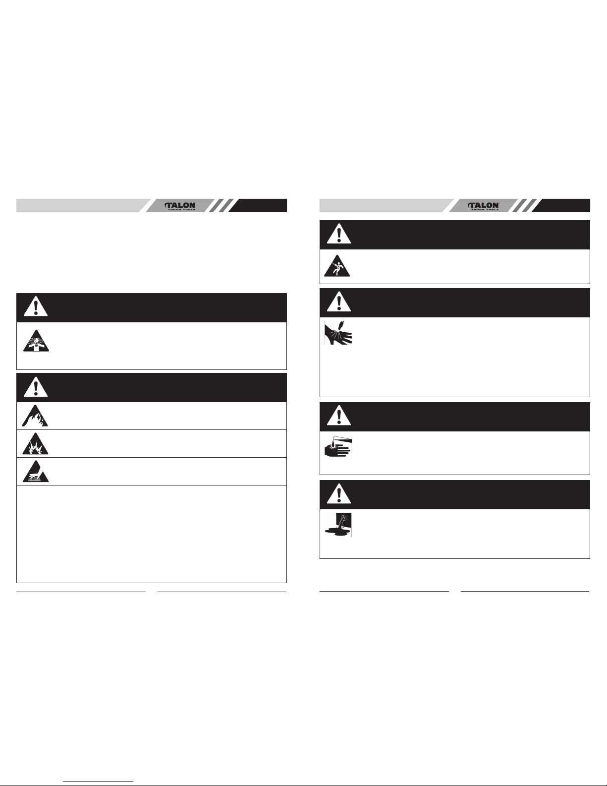
Talon Tools FH2700 User manual

7096-270003
WARNING • PLEASE READ
For your own safety please read this manual before attempting to operate your new unit. Failure to follow instructions
can result in serious personal injury. Spend a few moments to familiarize yourself with your petrol high pressure
cleaner before each use.
PETROL HIGH PRESSURE CLEANER WARRANTY
The benefits conferred by this warranty are in addition to all other conditions and warranties in respect of this
product which the consumer may have taken under the Trade Practices Act 1974 or by any legislation of a
State or Territory of Australia. This product is warranted for home use by Talon Tools Australia (ABN 12 099
520 939)(the “Company”) to be free from defects in material and workmanship for a period of 24 months from
the date of original purchase. The Company during the period of the warranty, will at its option, and subject
to the conditions stated herein, repair or replace without charge this product or any component part, which
upon examination by an Authorised Service Agent or by the Company is found to be defective.
Warranty conditions
This warranty will not apply:
(i) where this product has been subjected to misuse, abuse, accident or want of care;
(ii) where this product has been used for a purpose for which it was not designed or is not suited;
(iii) where the service of this product has been undertaken by a person not authorised by the Company
to carry out such work or where parts that have not been approved by the Company have been used;
(iv) where this product has been used for industrial or commercial purposes.
Should service become necessary during the warranty period, the purchaser should contact an Authorised
Service Agent or the Company. In order to obtain warranty service, the purchaser must present the store
receipt showing the name of the retailer and the date of purchase together with a completed Warranty
Card. The period of the warranty begins from the original date of purchase, notwithstanding any subse-
quent repair or parts replacement. No additional warranty or guarantee other than set out in this document,
whether written or verbal, is authorised to be made on the Company's behalf. The purchaser shall be
responsible for delivery or causing the product to be delivered to the Company or the Authorised Service
Agent and the purchaser shall be responsible for all charges in connection with re-delivery of the product
and/or the delivery of parts. Damage in transit is not covered by this warranty and purchasers should
remove from the product any liquids (if applicable) before sending and pack the product securely to pre-
vent damage.
Warranty exclusions
Normal wear parts or components are subject to separate terms as follows: Normal wear parts, compo-
nents or service required when performing normal and regular maintenance of this product are not covered
by warranty unless it is found to be defective by an Authorised Service Agent or by the Company. Normal
wear parts include, but are not limited to:
Returns based on the above listed normal wear parts will not be accepted under this warranty as they
are considered consumable items and are at the expense of the purchaser.
Nozzles
Hose
Failure caused by mineral or other deposits in
the Pump, Hose, Spraygun or Nozzles
1
Model. FH2700
Model. FH2701
USER MANUAL
Petrol High Pressure Cleaner
MODEL NO. FH2700/FH2701
WARRANTY INFORMATION AU

This manual covers the operation and maintenance of Talon High Pressure Cleaner. Please read and
understand this manual before using your new High Pressure Cleaner. If assistance is required, please
contact Talon Tools Australia or any Talon Tools Authorised Servicing Dealer.
To emphasise special information the DANGER, WARNING and CAUTION icons are used, please
observe these carefully.
Congratulations on your purchase of a quality Talon product.
WARRANTY...................................................................................................................... 1
INTRODUCTION............................................................................................................... 2
GENERAL SAFETY RULES............................................................................................ 4-6
TECHNICAL SPECIFICATIONS...................................................................................... 7
GENERAL IDENTIFICATION........................................................................................... 8
ASSEMBLY INSTRUCTIONS........................................................................................... 9-13
STARTING THE ENGINE................................................................................................. 14
PRE-OPERATION............................................................................................................. 15-16
OPERATION..................................................................................................................... 17-21
SPRAY LANCE................................................................................................................. 21-23
CHEMICALS & CLEANING SOLVENTS......................................................................... 23
TROUBLE SHOOTING..................................................................................................... 24
INDEX
NEVER fill fuel tank when engine is running or hot. Do not smoke when filling fuel tank.
NEVER fill fuel tank completely. Fill tank to 13mm below bottom of filler neck to provide space for fuel
expansion. Wipe any fuel spillage from engine and equipment before starting engine.
NEVER run engine indoors or in enclosed, poorly ventilated areas. Engine exhaust contains carbon
monoxide, an odorless and deadly gas.
DO NOT let hoses come in contact with very hot engine muffler during or immediately after use of
your pressure washer.
Damage to hoses from contact with hot engine surfaces will NOT be covered by warranty.
NEVER pull water supply hose to move pressure washer. This could damage hose and/or pump inlet.
DO NOT use hot water, use cold water only.
NEVER turn water supply off while pressure washer engine is running or damage to pump will result.
DO NOT stop spraying water for more than one minute at a time. Pump operates in bypass mode
when spray gun trigger is not pressed. If pump is left in bypass mode for more than one minute
internal components of the pump can be damaged.
WARNING
CAUTION
2
When using the high pressure setting, DO NOT allow the high pressure spray to come in contact with
unprotected skin, eyes, or with any pets or animals. Serious injuries can occur.Your washer operates
at fluid pressures and velocities high enough to penetrate human and animal flesh, which could result
in amputation or other serious in juries. Leaks caused by loose fittings or worn or damaged hoses can
result in injection injuries. DO NOT TREAT FLUID INJECTION AS A SIMPLE CUT! See a physician
immediately!
DANGER
3
INTRODUCTION AU INDEX AU

4
Talon High Pressure Cleaners are designed to give safe and dependable service if operated according to
instructions. Read and understand this user manual before operating your High Pressure Cleaner. You
can help prevent accidents by being familiar with your machines controls, and by observing safe
operating procedures.
PLEASE READ AND SAVE THESE
INSTRUCTIONS
Safety Information
DANGER - TOXIC FUMES
1. Operate pressure washer in a well ventilated area. Avoid enclosed areas such as
garages, basements etc.
2. Never operate unit in a location occupied by humans or animals.
3. Use only cleaning fluids specifically recommended for high pressure washers.
Follow manufacturers recommendations. Do not use chlorine bleach or any other
corrosive compound.
RISK OF EXPLOSION OR FIRE
EXPLOSIONS CAN CAUSE SEVERE BURNS
HOT SURFACES
1. Shut off engine and allow it to cool before adding fuel to the tank.
2. Use care in filling tank to avoid spilling fuel. Move pressure washer away from fueling area before
starting engine.
3. Keep maximum fuel level 13mm below top of tank to allow for expansion.
4. Operate and fuel equipment in well ventilated areas free from obstructions. Equip areas with fire
extinguisher suitable for gasoline fires.
5. Never operate pressure washer in an area containing dry brush or weeds.
6. Always keep pressure washer a minimum of four feet away from surfaces (such as houses, auto
mobiles, or live plants) that could be damaged from muffler exhaust heat.
7. Store fuel in an approved container, in a secure location away from work area.
8. Do not spray flammable liquids.
9. During operation, touch only the control surfaces of the pressure washer. Keep children away from
the pressure washer at all times. They may not be able to recognise the hazards of this product.
WARNING - FIRE AND BURN HAZARDS
GENERAL SAFETY RULES AU GENERAL SAFETY RULES AU
DANGER - RISK OF ELECTRIC SHOCK
• Unplug any electrically operated product before attempting to clean it. Direct spray
away from electric outlets and switches.
DANGER - RISK OF FLUID INJECTION
1. Never place hands in front of nozzle.
2. Direct spray away from self and others.
3. Make sure hose and fittings are tightened and in good condition. Never hold onto
the hose or fittings during operation.
4. Do not allow hose to contact muffler.
5. Never attach or remove wand or hose fittings while system is pressurised.
6. To relieve system pressure, shut off engine, turn off water supply, and pull gun
trigger until water stops flowing.
7. Use only hoses and accessories rated for pressure higher than your pressure
washer's PSI.
WARNING - RISK OF CHEMICAL BURN
1. Do not use acids, petrol, kerosene, or any other flammable materials in this product.
Use only household detergents, cleaners and degreasers recommended for use in
pressure washers.
2. Wear protective clothing to protect eyes and skin from contact with
sprayed materials.
DANGER - RISK OF INJURY OR PROPERTY DAMAGE WHEN
TRANSPORTING OR STORING
• If pressure washer is equipped with a fuel shut-off valve, turn the valve to the off
position before transporting to avoid fuel leaks. If pressure washer is not equipped
with a fuel shut-off valve, drain the fuel from tank before transporting. Always place
pressure washer on a protective mat when transporting to protect against damage to
vehicle from leaks. Remove pressure washer from vehicle immediately upon arrival at
your destination.
5

6 7
DANGER - RISK OF UNSAFE OPERATION
1. Do not use chlorine bleach or any other corrosive compound.
2. Become familiar with the operation and controls of the pressure washer.
3. Keep operating area clear of all persons, pets, and obstacles.
4. Do not operate the product when fatigued or under the influence of alcohol or drugs.
Stay alert at all times.
5. Never defeat the safety features of this product.
6. Do not operate machine with missing, broken, or unauthorised parts.
7. Never leave the spray lance unattended while unit is running.
8. If engine does not start after two pulls, squeeze trigger of gun to relieve
pump pressure. Pull starter cord slowly until resistance is felt. Then pull cord rapidly to
avoid kickback and prevent hand or arm injury.
9. Keep children away from the pressure washer at all times.
10. Do not overreach or stand on an unstable support.
11. Do not use pressure washer while standing on a ladder.
12. Grip gun/wand firmly with both hands. Expect the gun to kickback when triggered.
DANGER - RISK OF INJURY FROM SPRAY
1. Always wear approved safety glasses.Wear protective clothing to protect against
accidental spraying.
2. Never point spray lance at, or spray people or animals.
3. Always secure trigger lock when wand is not in service to prevent accidental
operation.
4. Never permanently secure trigger in pull back (open) position.
GENERAL SAFETY RULES AU TECHNICAL SPECIFICATIONS AU
TECHNICAL INFORMATION
SPECIFICATION FH2700/FH2701
ENGINE TYPE Air cooled, 4-cycle, Chrome Cylinder
ENGINE/MOTOR 6.5HP OHV
PUMP TYPE Annovi (RMV 25G27)
RATED PRESSURE 186 Bar (2700 PSI)
MAX. NOZZLE PRESSURE 220 Bar (3200 PSI)
FUEL TANK CAPACITY 3.6 Litres
OIL CAPACITY 0.6 Litres
WATER FLOW 9.3 L/M
WHEELS 8 inch rubber wheels
HOSE LENGTH 7.5 metres
SPRAY NOZZLES 5 Quick Connect Tips (Max 0O, High 15O, General 25O,
Delicate 40O, Detergent 65O)
SPRAY GUN Stainless Steel
QUICK CONNECT Yes
WEIGHT 36.5kg / 38kg

98
KNOW YOUR PETROL HIGH PRESSURE CLEANER
GENERAL IDENTIFICATION AU
1
2
4
11
3
5
6
7
8
9
24
22
21
20
13
19
10
16
18
17
23
1. High Pressure Gun
2. High Pressure Hose
3. Air Filter
4. Throttle Lever
5. Choke Lever
6. Fuel Lever
7. Spray Wand
8. Quick Connect Fitting
9. 8î Wheels
10. Starter Handle
11. Oil Fill Cap
12. ON/OFF Switch
13. Chemical Injection Siphon/Filter
14. Fuel Tank
15. Fuel Filler Cap
16. Knob Assembly
17. 5 Quick Connect Spray Nozzles
18. Gun/Hose Storage Handle (Frame)
19. High Pressure Outlet
20. Water Inlet with Filter
21. Thermal Relief Valve
22. Hose Reel (FH2701)
23. Detergent Tank (FH2701)
24. Hose Through Slot (FH2701)
3-1. PREPARING PRESSURE WASHER FOR USE
To prepare your pressure washer for operation, you will need to perform these tasks:
• Attach accessory tray to handle, then attach handle to main unit.
• Add oil to engine crankcase.
• Add fuel to fuel tank.
• Connect high pressure hose to spray gun and pump.
• Connect water supply to pump.
• Attach nozzle extension to spray gun.
• Select/attach quick connect nozzle to nozzle extension.
3-2. ATTACH HANDLE AND ACCESSORY TRAY-FH2700
NOTE: All assembly operations given in this section will be described from the perspective of
assembling the pressure washer from the rear.
1. Place the handle assembly (A) onto the handle supports (B) connected to the main unit. Make sure
the holes in the handle align with the holes on the handle supports (Fig. 3-2A).
NOTE: It may be necessary to move the handle supports from side to side in order to align the handle
so it will slide over the handle supports.
2. Insert the "J" bolt (C) through the hole on the right side of the handle (viewing from rear of unit) and
attach the plastic knob. Tighten the knob by hand (Fig. 3-2B).
3. Insert the carriage bolt (D) through the right side hole from the outside of the unit and attach a screw
from the inside of the unit (viewing unit from the rear). Tighten by hand or wrench. (Fig. 3-2C)
4. Insert “U” bolt (E) through the hole adjacent to the accessory tray on the right side of the handle. Fit
nut to the inside and tighten with spanner (not provided) Fig 3-2D & Fig 3-2E.
Fig 3-2A
Fig 3-2B
A
B
Fig 3-2C
3. ASSEMBLY INSTRUCTIONS
12 C
DE
CD
Fig 3-2D
E
Fig 3-2E
ASSEMBLY INSTRUCTIONS AU

10
3-4. CONNECT HOSE AND WATER SUPPLY TO PUMP-FH2700
IMPORTANT
You must assemble the nozzle extension and attach all hoses before you start the engine. Starting
engine without all hoses connected and water supplied will damage the pump.
1. Connect high pressure hose to pump outlet. (Fig. 3-4A).
2. Connect quick coupler male to water inlet. NOTE:Water source must provide a minimum of 1.3L per minute at 20
PSI. (Fig. 3-4B).
3. Attach the other female end of the hose to the base of the spray gun (Fig. 3-4C).
4. Place the nozzle holder onto the accessory tray (located on the handle assembly) and push each nozzle holder
into place (Fig. 3-4D).
5. Before you connect your garden hose to the water inlet, inspect the inlet screen (Fig. 3-4E). Clean the screen if it
contains debris, replace it if it is damaged. DO NOT RUN THE PRESSURE WASHER IF THE SCREEN IS DAM-
AGED. NEVER SIPHON INLETWATER.
6. Run water through the garden hose for 30 seconds to clean out any debris. Turn off water.
7. Disassemble the coupler female by turning nut anticlockwise (Fig. 3-4F).
8. Have the garden hose get through the nut, then attach it to the quick coupler female . Turn the nut clockwise to
assemble with the coupler (Fig. 3-4G).
9. Connect the quick coupler female and male (Fig. 3-4H).
11
ASSEMBLY INSTRUCTIONS AU
A
B
Fig 3-3A
Fig 3-3B
C
D
3-3. ATTACH HANDLE AND ACCESSORY TRAY-FH2701
NOTE: All assembly operations given in this section will be described from the perspective of assembling the pressure
washer from the rear.
1. Place the handle assembly (A) onto the handle supports (B) connected to the main unit. Make sure the holes in the
handle align with the holes on the handle supports (Fig. 3-3A).
NOTE: It may be necessary to move the handle supports from side to side in order to align the handle so it will slide
over the handle supports.
2. Insert the bolt (C) through the hole on the both side of the handle (D) and attach the plastic knob. Tighten the knob
by hand (Fig. 3-3B).
ASSEMBLY INSTRUCTIONS AU
Fig 3-4A Fig 3-4B Fig 3-4C
Fig 3-4D Fig 3-4E
Fig 3-4F Fig 3-4G Fig 3-4H

CAUTION
There MUST be at least ten feet of unrestricted garden hose between the pressure washer inlet and
any flow shut-off device, such as a 'Y' shut-off connector or other convenience-type water shut-off
valves. Damage to pressure washer resulting from disregarding this caution will not be covered by the
warranty. Turn ON the water and squeeze the trigger on the spray gun to purge the pump system of
air and impurities. Before starting the pressure washer, be sure you are wearing adequate eye protec-
tion.
3-6. CHECKLIST BEFORE STARTING ENGINE
Review the unit's assembly to confirm you have performed all of the following:
1. Make sure the handle is in place and secure.
2. Check that oil has been added to the proper level in the engine crankcase.
3. Add proper petrol to fuel tank.
4. Check for properly attached hose connections.
5. Check to make sure that there are no kinks, cuts, or damage to the high pressure hose.
6. Provide a proper water supply at an adequate flow.
7. Be sure to read "Safety Rules" and "How To Use Your Pressure Washer" before using the
pressure washer.
12
3-5. CONNECT HOSE AND WATER SUPPLY TO PUMP-FH2701
ASSEMBLY INSTRUCTIONS AU
1. Connect high pressure hose (B) to pump outlet. (A) (Fig. 3-5A).
2. Connect the pump high pressure hose (C) with the winding wheel. (D) (Fig. 3-5B).
3. Attach the other female end of the hose to the base of the spray gun (Fig. 3-5C).
4. Run water through the garden hose for 30 seconds to clean out any debris. Turn off water.
5. Disassemble the coupler female by turning nut anticlockwise (Fig. 3-5D).
6. Have the garden hose get through the nut, then attach it to the quick coupler female .
Turn the nut clockwise to assemble with the coupler (Fig. 3-5E).
7. Connect the quick coupler female and male (Fig. 3-5F).
B
ACD
Fig 3-5C
Fig 3-5D Fig 3-5E Fig 3-5F
Fig 3-5A Fig 3-5B
ASSEMBLY INSTRUCTIONS AU
3-7. WORKING WITH DETERGENTS-FH2701
1. Open the Upper tank cap (A). (Fig. 3-7A)
2. Refill directly cleaning (C) solution to chemical tanks (B). (Fig. 3-7B)
3. Close the Upper tank (A) after refill. (Fig. 3-7C)
4. Before loading cleaning solutions, make sure the chemical hose (D) is onto
barbed fitting (E). (Fig. 3-7D)
NOTE: For every 7 gallons of water pumped 1 gallon of chemical/cleaning solu-
tion will be used.
Fig. 3-7A Fig. 3-7B Fig. 3-7C
A
B
A
C
Fig. 3-7D
Fig. 3-8A Fig. 3-8B Fig. 3-8C
3-8. HOSE REEL OPERATION-FH2701
1. Pull out the hose reel handle (A).You will feel it spring into place when correctly positioned
(Fig. 3-8A).
Use the handle to roll the high pressure hose onto or off the reel. Ensure hose does not become twisted or kinked
when rolling.
AA
13
D
E

OFF
ON
OPEN
CLOSE
FAST
SLOW
1. Move the fuel valve (A) to the ON position. (Fig. 4-1A)
2. Move choke lever (B) to CLOSE position for cold engine starting. Turn choke lever (B) to OPEN
position for warm engine starting.(Fig. 4-1B)
3. Move the throttle lever (C) fully to the left (fast).(Fig. 4-1C)
4. Start engine
(a) Turn the engine switch (D) to the ON position. (Fig. 4-1D)
(b) Grasp starter handle (E). Pull slowly until you can feel drag against you, and then pull rapidly.
( Fig. 4-1E)
5. Set the throttle lever (C) at the desired speed.(Fig. 4-1C)
CAUTION
Do not suddenly release starter handle and let it snap back. The correct way is to slowly let the handle
return to engine. When engine warms up, gradually move the choke lever to the OPEN position.
NOTE: If the recoil start is hard to pull, it may be necessary to squeeze the spray gun trigger to relieve
internal pump pressure.
4.1 TO STOP ENGINE
In an emergency, stop the engine by turning the engine switch to the OFF position. Generally, use the
following procedure:
1. Move the throttle lever (C) fully to the right. (Fig. 4-1C)
2. Turn the engine switch (D) to the OFF position. (Fig. 4-1D)
3. Turn fuel valve (A) to the OFF position.(Fig. 4-1A)
Low oil Shutdown System
The Low oil Shutdown system is designed to prevent engine damage caused by an insufficient amount of
oil in the crankcase. Before the oil level in the crankcase can fall below a safe limit, the Low Oil Shutdown
system will automatically shut down the engine (the engine switch will remain in the ON position). If the
Low Oil Shutdown system shuts down the engine, add engine oil.
4. STARTING THE ENGINE
14
Fig 4-1A Fig 4-1B Fig 4-1C
Fig 4-1D Fig 4-1E
C
FAST
SLOW
AB
E
STARTING THE ENGINE AU
5.1 ENGINE OIL
5. PRE-OPERATION
CAUTION
• Engine oil is a major factor affecting engine performance and service life. Non-detergent and 2-
stroke engine oil are not recommended.
• Be sure to check the engine on a level surface with the engine stopped.
SAE 15W-40 is recommended for general, all-temperature use.
1.Remove the oil filler cap/dipstick and wipe it clean (Fig. 5-1A).
2.Check the oil level by inserting the dipstick in the filler neck without
screwing it in.
3.If the level is low, fill to the top of oil filler neck (B) with the
recommended oil (Fig 5-1B).
NOTE
The low oil shutdown system will automatically stop the engine before
the oil level falls below the safe limit. However, to avoid the
inconvenience of an unexpected shutdown, it is advisable to visually
inspect the oil level regularly.
5.2 FUEL
Unscrew the fuel cap. Check the fuel level. Your engine is designed to
use any petrol that has a pump octane number of 91 or higher. Petrol
pumps at service stations normally display the pump octane
number. We recommend that you use unleaded fuel because it pro-
duces fewer engine and spark plug deposits and extends the life of
exhaust system components. Never use stale or contaminated gasoline
or an oil/gasoline mixture.
Avoid getting dirt, dust or water in the fuel tank. Use of a lower octane
gasoline can cause persistent "pinging" or heavy "spark knock" (a
metallic rapping noise) which, if severe, can lead to engine damage.
CAUTION
If "spark knock" or "pinging" occurs at a steady engine speed under normal load, change brands of
petrol. If spark knock or pinging persists, consult your authorised Talon dealer.
Failure to do so is considered misuse, and damage caused by misuse is not covered by Warranty.
Occasionally you may experience light spark knock while operating under heavy loads. This is no
cause for concern, it simply means your engine is operating efficiently. After refueling, be sure to
tighten the fuel tank cap firmly.
FUEL TANK CAPACITY: FH2700/FH2701 3.6 L
30
10W-30
5W-30
Fig 5-1A
Fig 5-1B
PRE-OPERATION AU
15
D

WARNING
• Petrol is explosive under certain conditions.
• Refuel in a well-ventilated area with the engine stopped. Do not smoke or allow flames or sparks in
the area where the engine is refueled or where gasoline is stored.
• Do not overfill the fuel tank (there should be no fuel in the filler neck.) After refueling, make sure the
tank cap is closed properly and securely.
• Be careful not to spill fuel when refueling. Spilled fuel or fuel vapor may ignite. If any fuel is spilled,
make sure the area is dry before starting the engine.
• Avoid repeated or prolonged contact with skin or vapor.
PETROL CONTAINING ALCOHOL
If you decide to use a gasoline containing alcohol (gasohol), be sure it's
octane rating is at least as high as that recommended by Talon. There
are two types of gasohol :one containing ethanol, and the other
containing methanol. Do not use gasohol that contains more than 10%
ethanol. Do not use gasoline containing methanol (methyl or wood
alcohol) that does not also contain cosolvents and corrosion inhibitors
for methanol. Never use gasoline containing more than 5% methanol,
even if it has cosolvents and corrosion inhibitors.
NOTE
• Fuel system damage or engine performance problems resulting from the use of fuels that contain
alcohol is not covered under warranty. Talon cannot endorse the use of fuels containing methanol
since evidence of their suitability is as yet incomplete.
• Before buying fuel from an unfamiliar station, try to find out if the fuel
contains alcohol, if it does, confirm the type and percentage of alcohol
used. If you notice any undesirable operating symptoms while using a
gasoline that contains alcohol, or one that you think contains alcohol,
switch to a gasoline that you know does not contain alcohol.
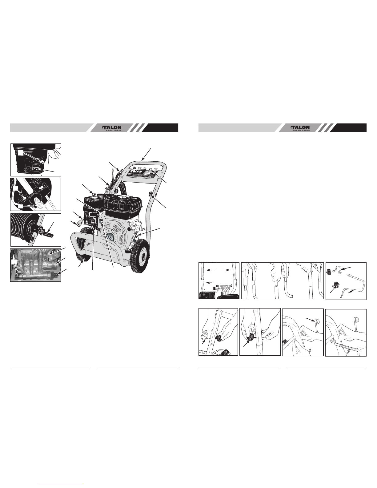
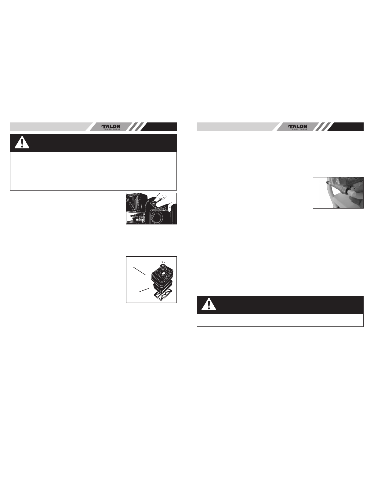
5.3 AIR CLEANER SERVICE (Fig 5-3A)
Remove the knob, washer and air cleaner cover. Check the element for
dirt or obstruction. Clean the element if necessary.
1. Unscrew the wing nut, remove the air cleaner cover and remove
the air cleaner element.
2. Wash the air cleaner element in a solution of household detergent
and warm water, or wash in
nonflammable or high flashpoint solvent. Allow the element to dry thoroughly.
3. Soak the element in clean engine oil, and squeeze out the excess oil. The engine will smoke during
initial start-up if too much oil is left in the foam.
4. Reinstall the air cleaner element and the cover.
16 17
Fig 5-2A
Fig 5-3A
Air Cleaner
Element
Air Cleaner
Cover
PRE-OPERATION AU
6. OPERATION
6.1 STARTING
Prior to starting, refer to your engine manual for proper starting procedure.
1. In a well ventilated outdoor area add fresh, high quality, unleaded gasoline with a pump octane rating
of 91 or higher. Do not overfill. Wipe up spilled fuel before starting the engine. Refer to Engine Owners
Manual for correct procedure.
2. Check engine oil level. See Engine Owners Manual for correct procedure.
NOTE: There will be a slight amount of oil in the engine from factory testing.
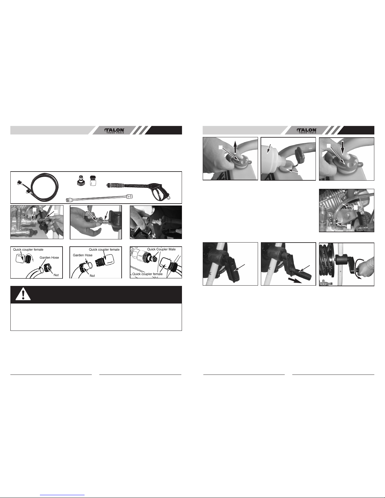
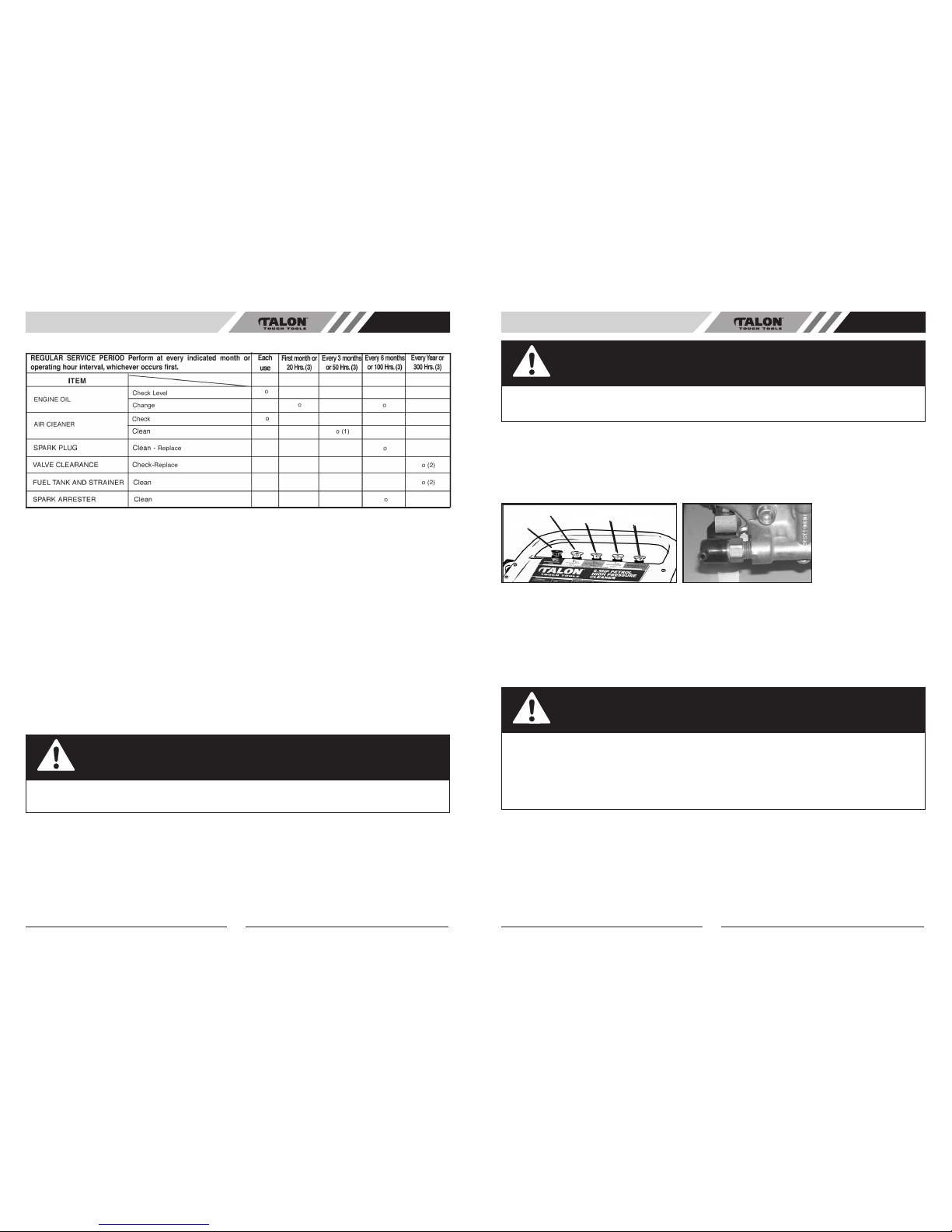
3. Verify the filter screen (Fig. 6-1A) is in water inlet of pump. NOTE: Cone side faces out.
4. Connect water source to pump inlet.
NOTE: Water source must provide a minimum of 1.3L per minute at 20
PSI.
5. Connect high pressure hose to pump outlet.
6. If applying a chemical or cleaning solution, see How To Apply
Chemicals/Cleaning Solvents instructions in this section.
7. Turn water source on.
NOTE: Failure to do so could cause damage to the pump.
8. Start engine. See Engine Owners Manual for correct procedure.
NOTE: When engine rope is pulled, pressure starts building in the gun.
If the engine does not start after two pulls, pull the gun trigger to relieve this pressure.
9. Depress trigger on gun to start water flow.
NOTE: Stand on a stable surface and grip gun/spray wand firmly with both hands. Expect the gun to
kick when triggered.
10. Release trigger to stop water flow.
11. Adjust spray for the task being performed by changing quick connect nozzle. See How To Use Spray
Wand instructions in this section.
WARNING
Once the engine is running, never let the spray gun stop spraying water for more than 2 minutes.
The circulating water in the pump can accumulate heat and cause internal damage to the pump.
6.2 SHUTTING DOWN
1. After each use, if you have applied chemicals, place chemical hose into container of clean water and
draw clean water through chemical injection system to rinse system thoroughly. NOTE: Failure to do so
could cause damage to the pump.
2. Turn engine off. See Engine Owner’s Manual. NOTE: NEVER turn the water off with the engine
running.
3. Turn water source off.
4. Pull trigger on spray gun to relieve any water pressure in hose or spray gun.
5. See Storage section in this manual for proper storage procedures.
Fig 6-1A
OPERATION AU

18
OPERATION AU
6.3MAINTENANCESCHEDULE
NOTE
(1)Servicemorefrequentlywhenusedindustyareas.
(2)TheseitemsshouldbeservicedbyanauthorizedTalondealer.
6.4BASICELEMENTSOFA PRESSUREWASHER
•HighPressurePump:Increasesthepressureofthewatersupply.
•Engine:Drivesthehighpressurepump.
•HighPressureHose:Carriesthepressurisedwaterfromthepumptothegunandspraywand.
•SprayGun:Connectswithspraywandtocontrolwaterflowrate,direction,andpressure.
•QuickConnectSprayWand:Allowstheusertoquicklychangehigh-pressurenozzles.SeeHowTo
UseSprayLanceinstructionsinthissection.
•ChemicalHose(notshown):Feedscleaningagentsintothepumptomixwiththewater.SeeHowTo
ApplyChemicals/CleaningSolventsinstructionsinthissection.
6.5PRESSUREWASHERTERMINOLOGY
•PSI:PoundsperSquareInch.Theunitofmeasureforwaterpressure.Alsousedforairpressure,
hydraulicpressureetc.
•L/M:LitersPerMinute.Theunitofmeasurefortheflowrateofwater.
•BypassMode:Allowswatertore-circulatewithinpumpwhentheguntriggerisnotpulled.
CAUTION
Allowingtheunittorunformorethanoneminutewithouttheguntriggerpulledcouldcause
overheatinganddamagetothepump.
6.6PRESSUREWASHEROPERATINGFEATURESPRESSUREADJUSTMENTS
Thepressuresettingispresetatthefactorytoachieveoptimumpressureandcleaning.Ifyouneedto
lowerthepressure,itcanbeaccomplishedbythesemethods.
1.Backawayfromthesurfacetobecleaned.Thefurtherawayyouare,thelessthepressurewillbeon
thesurfacetobecleaned.
2.Changetothe40°nozzle-(white)thisnozzledeliversalesspowerfulstreamofwaterandawider
spraypattern(Fig6-6A).
3.Reducethespeedofthegasolineengine(RPM).Slowtheenginedownandthewaterpressurewill
godownwithit.
19
CAUTION
DONOT attempttoincreasepumppressure.A higherpressuresettingthanthefactorysetpressure
maydamagepump.
THERMAL RELIEFVALVE
Whenthetemperatureinsidethepumprisestoohighthevalvewillopenandreleaseagushofwaterin
anefforttolowerthetemperatureinsidethepump.Thevalvewillthenclose(Fig.6-6B).
Fig6-6BFig6-6A
Black
White Green Yellow Red
6.7OIL CHANGE
Draintheoilwhileengineisstillwarmtoassurerapidandcompletedraining.
1.Removethedrainplug,thendraintheoil.
2.Refillwiththerecommendedoiltothespecifiedlevel.
3.Reinstallthedrainplugandtightensecurely.
OIL CAPACITY:0.6Litres
CAUTION
Usedmotoroilmaycauseskincancerifrepeatedlyleftincontactwiththeskinforprolongedperiods.
Althoughthisisunlikelyunlessyouhandleusedoilonadailybasis,itisstilladvisabletothoroughly
washyourhandswithsoapandwaterassoonaspossibleafterhandlingusedoil.
NOTE: Pleasedisposeofusedmotoroilinamannerthatiscompatiblewiththeenvironment.We
suggestyoutankitinasealedcontainertoyourlocalservicestationforreclamantion.Donotthrowit
inthetrashorpouritontheground.
OPERATION AU

20 21
OPERATION AU
OIL FILLER CAP /
DIPSTICK
DRAIN
PLUG
6.8 SPARK PLUG SERVICE
To ensure proper engine operation, the spark plug must be properly gapped and free of deposits.
1. Remove the spark plug
If the engine has been running, the muffler will be very hot. Be careful not to touch the muffler (A).
(Fig. 6-8A)
2. Visually inspect the spark plug. Discard it if the insulator is cracked or chipped. Clean the spark plug
with a wire brush if it is to be reused.
3. Measure the plug gap with a feeler gauge. The gap should be 0.7-0.8mm (0.028-0.031 in). Correct as
necessary be bending the side electrode (Fig 6-8B).
4. Check that the spark plug washer is in good condition, and thread the spark plug in by hand to pre-
vent crossthreading.
5. After the spark plug is seated, tighten with a spark plug wrench to compress the washer.
NOTE: If installing a new spark plug, tighten 1/2 turn after the spark plug seats to compress the washer.
If reinstalling a used spark plug, tighten 1/2-1/4 turn after the spark plug seats to compress the washer
(Fig 6-8C).
CAUTION
The spark plug must be securely tightened. An improperly tightened plug can become very hot and
damage the engine. Never use a spark plug with an improper heat range.
OFF
ON
Fig 6-7A Fig 6-7B Fig 6-7C
Fig 6-8A Fig 6-8B
Fig 6-8C Fig 6-8D Fig 6-8E
A
B
C
6.9 STORAGE
1. Drain the fuel
a. With the fuel valve in the ON position, remove the carburetor drain screw (B) (side of carburettor
bowl), and drain all the petrol from the fuel tank into a suitable container. (Fig. 6-8D)
b. Reinstall the carburetor drain screw (B) (Fig. 6-8D).
Gasoline is extremely flammable and is explosive under certain conditions. Perform this task in a well
ventilated area. Do not smoke or allow flames or sparks in the area during this procedure.
2. Change the engine oil.
3. Remove the spark plug and pour about a tablespoon of clean engine oil into the cylinder. Crank the
engine several revolutions to distribute the oil, then reinstall the spark plug.
4. Pull the starter rope slowly until resistance is felt. Continue pulling until the notch on the starter pulley
aligns with the hole on the recoil starter (see illustration below). At this point, the intake and exhaust
valves are closed, and this will help to protect the engine from internal corrosion (Fig. 6-8E).
5. Cover the unit to keep out dust.
7. HOW TO USE SPRAY LANCE
The nozzles for the spray wand are stored in nozzle holder on the panel assembly. Colors on the panel
identify nozzle location and spray pattern. See chart to choose the correct nozzle for the job to be
performed.
OPERATION/SPRAY LANCE AU

22 23
SPRAY LANCE AU
7.1 CHANGING NOZZLES ON SPRAY WAND
CAUTION
The high pressure spray from your pressure washer is capable of causing damage to surfaces such
as wood, glass, automobile paint, auto striping and trim, and delicate objects such as flowers and
shrubs. Before spraying, check the item to be cleaned to assure yourself that it is strong enough to
resist
damage from the force of the spray.
WARNING
Risk of Flying Object could cause risk of serious injury. DO NOT
attempt to change nozzles while pressure washer is running. Turn
engine off before changing nozzles.
1. Pull quick connect coupler back and insert nozzle.
2. Release quick connect coupler and twist nozzle to make sure it is
secure in coupler.
WARNING
Risk of Flying Object could cause risk of
serious injury. Ensure nozzle is completely
inserted in QC socket, and QC snap ring
is fully engaged (forward) before squeezing
gun trigger.
WARNING
Risk of injection or injury to person. Do not directly discharge stream toward persons, unprotected
skins, eyes, or any pets or animals. Serious injuries can occur.
7.2 SPRAY GUN TRIGGER
1. Release the lever (B) before press switch trigger. (Fig. 7-2A)
2. Trigger the gun to eliminate trapped air, wait for a steady flow of water to emerge from the
spray nozzle.
3. For safety use the trigger lock lever to prevent accidental operation. (Fig 7-2B)
Fig 7-1A
Fig 7-2A Fig 7-2B
B
7.4 HOW TO CLEAN THE WATER INLET FILTER
7.3 NOZZLE CLEANING
If the nozzle becomes clogged with foreign materials, such as dirt,
excessive pressure may develop.
If the nozzle becomes partially clogged or restricted, the pump
pressure will pulsate.
Clean the nozzle immediately using the nozzle kit supplied and the
following instructions:
1. Shut off the pressure washer and turn off the water supply.
2. Pull trigger on gun handle to relieve any water pressure.
3. Remove the high-pressure nozzle from the spray lance. Remove
any obstructions with the nozzle cleaning tool provided and backflush
with clean water.
4. Direct water supply into spray lance to backflush loosened
particles for 30 seconds.
5. Reassemble the nozzle to the lance.
6. Start pressure washer and place spray wand into high pressure
setting to test.
This screen filter should be checked periodically and cleaned if
necessary.
1. Remove filter by grasping end and removing it from water inlet of
pump as shown.
2. Clean filter by flushing it with water on both sides.
3. Re-insert filter into water inlet of pump. NOTE: Cone side faces
out.
NOTE: Do not operate pressure washer without filter properly
installed.
8. HOW TO APPLY CHEMICALS AND CLEANING SOLVENTS
Applying chemicals or cleaning solvents is a low pressure operation.
NOTE: Use only soaps and chemicals designed for pressure washer
use. Do not use bleach.
8.1 TO APPLY CHEMICALS
1. Press chemical hose onto barbed fitting (Fig. 8-1A)located near
high pressure hose connection of pump as shown.
2. Place other end of chemical hose with filter on it into container
holding chemical/cleaning solution.
NOTE: For every 7 litres of water pumped, 1 litre of chemical/cleaning
solution will be used.
3. Install low pressure (black) nozzle into quick connect fitting of
spray wand.
4. After use of chemicals, place chemical hose into container of clean
water and draw clean water through chemical injection system to
rinse system thoroughly. If chemicals remain in the pump it could be
damaged. Pumps damaged due to chemicals will not be covered
under warranty.
NOTE: Chemicals and soaps will not siphon when spray wand is in
the high pressure setting.
Fig 7-3A
Fig 7-4A
Fig 8-1A
Fig 8-1B
SPRAY LANCE/CHEMICALS AU

24
TROUBLESHOOTING AU
9. TROUBLESHOOTING THE PRESSURE WASHER
PROBLEM PROBABLE CAUSE CORRECTIVE ACTION
Pump has following problems: failure
to produce pressure, erratic pressure,
chattering, loss of pressure, low
water volume.
1. Low pressure nozzle installed.
2. Water inlet is blocked.
3. Inadequate water supply.
4. Inlet hose is kinked or leaking.
5. Clogged inlet hose.
6. Water supply is over 38oc
7. High pressure hose is blocked or
leaks.
8. Gun leaks.
9. Nozzle is obstructed.
10. Pump is faulty.
1. Replace nozzle with high pressure
nozzle.
2. Clear inlet.
3. Provide adequate water flow.
4. Straighten inlet hose patch leak.
5. Check and clean inlet hose.
6. Provide cooler water supply.
7. Clear blocks in outlet.
8. Replace gun.
9. Clean nozzle.
10. Contact Talon service facility.
Detergent fails to mix with spray. 1. Detergent siphoning tube is not
submergend.
2. Chemical filter is clogged.
3. Low pressure nozzle installed.
1. Insert detergent siphoning tube
into detergent.
2. Clean or replace filter/detergent
siphoning tube.
3. Replace nozzle with low pressure
nozzle.
Engine runs good at no-load but
“bogs” when load is added.
Engine speed is too slow. Move throttle control to FAST posi-
tion. If engine still “bogs down”,
contact Talon service facility.
Engine wil not start; or starts and
runs rough.
1. Low oil level.
2. Dirty air cleaner.
3. Out of gasoline.
4. Stale gasoline.
5. Spark plug wire not connected to
spark plug.
6. Bad spark plug.
7. Water in gasoline.
8. Over choking.
9. Excessively rich fuel mixture.
10. Intake valve stuck open or
closed.
11. Engine has lost compression.
1. Fill crankcase to proper level.
2. Clean or replace air cleaner.
3. Fill fuel tank.
4. Drain gas tank; fill with fresh fuel.
5. connect wire to spark plug.
6. Replace spark plug.
7. Drain gas tank; fill with fresh fuel.
8. Open choke fully and crank
engine.
9. Contact Talon service facility.
Engine shuts down during operation. 1. Out of gasoline.
2. Low oil level.
1. Fill fuel tank.
2. Fill crankcase to proper level.
Engine lacks power. Dirty air filter. Clean/Replace air filter.
Engine “hunts” or falters. Choke is opened too soon. Move choke to halfway position until
engine runs smoothly.
This manual suits for next models
1
Table of contents