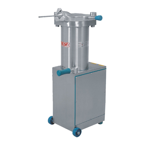
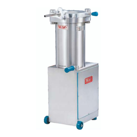
Talsa F14s Operating instructions

Version 1.3 • Revised 07/2018
ENGLISH
FRANÇAIS
DEUTSCH
ESPAÑOL
Your service distributor: ______________________________________ Tel: ________________________
Machine model: ________________________ Serial No.: ______________________________________
Fillers / Stuffers
OPERATING INSTRUCTIONS AND EU DECLARATION OF CONFORMITY
Before operating the unit read this manual thoroughly.
This manual should be retained for future reference.
Poussoirs
MODE D’EMPLOI ET DÉCLARATION DE CONFORMITÉ C E
Avant la mise en service de cette unité, prière de lire attentivement cette
notice d’utilisation que vous conserverez pour toute référence ultérieure.
Kolbenfüllmaschinen
BETRIEBSANLEITUNG UND EU-KONFORMITÄTSERKLÄRUNG
Vor Inbetriebnahme des Gerätes lesen Sie bitte diese Gebrauchsanleitung
gründlich durch und bewahren Sie sie für später auf.
Stopmachines
GEBRUIKSAANWIJZING EN EU-VERKLARING VAN OVEREENSTEMMING
Alvorens dit toestel in werking te stellen lees deze gebruiksaanwijzing
aandachtig door. Bewaar deze handleiding als naslagwerk.
Embutidoras
MANUAL DE INSTRUCCIONES Y DECLARACIÓN DE CONFORMIDAD C E
Antes de utilizar la unidad lea este manual detenidamente y consérvelo para
futuras consultas.
F14s • F25s • F35s • F50s
O
M
D
8
E
1
L
0
2
NEDERLANDS

F14s • F25s • F35s • F50s
Installation and Operating Manual .............................................................................................................. EN 1
Please read and comply with these original instructions priorto the initial operationof your machine and store them forlater use or subsequent owners.
Notice d’Installation et Utilisation .............................................................................................................. FR 1
Lire cette notice originale avant lapremière utilisation de votre appareil, se comporter selon ce qu’elle requiert et la conserver pour une utilisation ultérieure ou pour lepropriétaire futur.
Installations- und Betriebsanleitung........................................................................................................... DE 1
Lesen Sie vor der ersten Inbetriebnahme Ihres Gerätes bitte diese Originalbetriebsanleitung, handeln Siedanach und bewahren sie für späteren Gebrauch oder für Nachbesitzer auf.
Handleiding voor Installatie en Gebruik..................................................................................................... NL 1
Lees deze originele gebruiksaanwijzing door voordat u uw apparaat voor de eerste keer gebruikt, handel ernaar en bewaar het voor later gebruik of voor volgende eigenaars.
Manual de instalación y utilización............................................................................................................. ES 1
Antes del primer uso de su máquina, lea este manualoriginal,actúede acuerdo a sus indicaciones y guárdelo para un usoposterioro paraotro propietario posterior.

HYDRAULIC PISTON FILLERS F14/25/35/50 INSTALLATION AND OPERATING MANUAL
© Talsabell s.a. All rights reserved. EN - 1 V-1.3 last revision: 07/2018
Installation and Operating Manual
Hydraulic Piston Fillers / Stuffers
F14s • F25s • F35s • F50s
Talsa Products are designed and manufactured to the highest European standards. Proper installation, operation and maintenance are essential for best performance and years of trouble-free use.
This manual should be retained for future reference.
Read, understand and follow the instructions and warnings contained in this manual.
The information contained in this document isknown to be current and accurate at the timeof printing. Talsa isnot responsible for inaccuracies contained herein attributable to printing or transcription
errors. In line with our policy of continually improving our products, Talsa reserves the right to change materials and specifications without notice.
This manual contains proprietary information protected by intellectual property law. All rights reserved. No part of it may be photocopied, reproduced or translated into another language without the
prior written consent of the author.
Talsabell s.a.
Polígono Industrial V. Salud
Rambleta 8
46950 Xirivella (Valencia) - Spain
EORI: ESA46428025
www.talsanet.com

HYDRAULIC PISTON FILLERS F14/25/35/50 INSTALLATION AND OPERATING MANUAL
© Talsabell s.a. All rights reserved. EN - 2 V-1.3 last revision: 07/2018
Table of contents
1. For your safety..............................................................................................2
1.1 Definition of warnings and signal words..........................................................2
1.1.1 Safety warnings and signal words used in this manual...................................2
1.1.2 Safety warnings attached to the machines.....................................................2
1.2 Intended use of the machine...........................................................................2
1.3 Modifications...................................................................................................3
1.4 Important warnings..........................................................................................3
1.5 Operating Hazards..........................................................................................3
1.6 Electrical hazards............................................................................................4
1.7 Disposal..........................................................................................................4
1.8 Tips and useful information.............................................................................4
2. Description and characteristics of the machine........................................5
2.1 Content of delivery..........................................................................................5
2.2 Main elements.................................................................................................6
2.3 Standard and optional accessories.................................................................7
3. Technical specifications...............................................................................8
3.1 Capacities and weights...................................................................................8
3.2 Operating invironment.....................................................................................8
3.3 Noise level.......................................................................................................8
3.4 Hydraulic oil.....................................................................................................8
3.5 Power and connection values.........................................................................8
3.6 Dimensiones...................................................................................................9
4. Storage, delivery and unpacking...............................................................10
5. Installation...................................................................................................10
5.1 Placement.....................................................................................................10
5.2 Installation of the lid lock nuts and knee lever...............................................11
5.3 Installing casters (Option) .............................................................................12
5.4 Transport cap of the oil tank (machines sent lying).......................................13
5.5 Connecting to the power source ...................................................................14
5.6 Voltage change.............................................................................................14
6. Operating instructions................................................................................15
6.1 Steps to follow...............................................................................................15
6.2 Useful tips .....................................................................................................17
7. Cleaning.......................................................................................................18
7.1 Cleaning instructions.....................................................................................18
7.2 General cleaning recommendations .............................................................20
7.3 Recommended cleaning intervals.................................................................20
7.4 Stainless steel care.......................................................................................20
8. Maintenance ................................................................................................21
8.1 Maintenance and inspection intervals...........................................................21
8.2 Maintenance and inspection tips...................................................................21
8.3 Hydraulic oil...................................................................................................22
9. Trouble shooting.........................................................................................23
10. Declaration of conformity...........................................................................24
11. Labelled diagram and spare parts list.......................................................25
11.1 Labelled diagram of the machine..................................................................25
11.2 Parts list ........................................................................................................27
12. Electric diagrams........................................................................................29
12.1 Electric diagram 3-phase motors ..................................................................29
12.2 Electric diagram single-phase motors...........................................................30
12.3 Electric diagram 3-phase motor voltage change...........................................31

HYDRAULIC PISTON FILLERS F14/25/35/50 INSTALLATION AND OPERATING MANUAL
© Talsabell s.a. All rights reserved. EN - 2 V-1.3 last revision: 07/2018
1. For your safety
The following instructions limit the liability of the manufacturer and his representatives.
1.1 Definition of warnings and signal words
1.1.1 Safety warnings and signal words used in this manual
The safety instructions serve as indications and precautionary measures that must be taken into account or adopted to avoid a dangerous situation.
This is the safety alert symbol. It is used to alert you to personal injury hazards. Obey all safety messages that follow this symbol to avoid possible injury or death.
Warnings can be classified according to the severity of the hazardous situation. The classification is based on an assumption of probability of being exposed to a dangerous situation and what
could happen in such a case. There are four kinds of warnings:
indicates a hazardous situation which, if not avoided, will result in death or serious injury.
indicates a hazardous situation which, if not avoided, could result in death or serious injury.
indicates a hazardous situation which, if not avoided, may result in minor or moderate injury.
is used to address practices not related to personal injury.
Important information:
NOTE: provides additional information to clarify or simplify a procedure.
1.1.2 Safety warnings attached to the machines
The safety symbols warn of special hazards and are placed in the relevant places on the machine. Check warning symbols daily:
■Are all security symbols present?
■Are all safety symbols recognizable and readable?
Ensure that the safety plates / adhesives are firmly attached to the machine, are easily readable and are not erased during the cleaning process. Disconnect the machine and secure the main
switch against reconnection if a warning symbol is missing or no longer recognizable. Do not reconnect the machine until they are in place and all safety symbols are recognizable. If they become
damaged or lost, contact your authorized dealer.
1.2 Intended use of the machine
In general, the hydraulic piston fillers/stuffers are used to prepare sausages made of minced meat. Other applications include dough or paste of any type that can flow through a nozzle/horn of Ø
10mm. Never use hard masses or pastes that do not flow and could cause dangerous overpressure.
The temperature of the dough to be stuffed should be higher than 2ºC (35ºF).Do not process frozen or semi-frozen doughs.
Working environment conditions: temperature +5 to + 40ºC (+40 to + 100ºF), relative humidity: 20 to 90%.
The maximum operating pressure must not exceed 120 bar.
Any other use would conflict with the machine’s characteristics, the manufacturer is not liable for any damages that may occur as a result of improper use.

HYDRAULIC PISTON FILLERS F14/25/35/50 INSTALLATION AND OPERATING MANUAL
© Talsabell s.a. All rights reserved. EN - 3 V-1.3 last revision: 07/2018
1.3 Modifications
Disclaimer of liability
It isnot allowedto modify themachine without theprior express authorization of Talsa,neither in itsdesign norin its securitysystems. Talsa willnot be liable fordamages causedby arbitrary changes.
When auser makesessential modifications tothe machine,he assumesthe manufacturer status. Insuch acase, he shallbeobliged totake allthe measures incumbenton itlegallyas amanufacturer.
The original manufacturer is therefore released from its responsibility.
Genuine parts
ThemachineisonlyallowedtobeusedwithoriginalTalsaaccessoriesandspareparts. Talsawillnotbeliablefordamagescausedbyusingtools,accessoriesorsparepartsfromothermanufacturers.
1.4 Important warnings
Since the WARNINGS, CAUTIONS and INSTRUCTIONS in this manual cannot address all possible conditions and situations that may arise, the operator MUST ALWAYS exercise common sense
and due caution when using this machine!
DO NOT DISCARD THIS MANUAL; KEEP IT FOR FUTURE REFERENCE BY ALL USERS AND MAINTENANCE PERSONNEL. PLEASE THOROUGHLY READ AND FULLY
UNDERSTAND ALL THE INSTRUCTIONS BEFORE SERVICING OR USING THE MACHINE.
THIS MACHINE HAS MOVING PARTS AND USES VOLTAGES THAT ARE POTENTIALLY HAZARDOUS. FAILURE TO FOLLOW THE INSTRUCTIONS CONTAINED IN THIS
MANUAL COULD RESULT IN SEVERE, POSSIBLY LIFE-THREATENING, PERSONAL INJURY.
THIS MACHINE HAS BEEN DESIGNED EXCLUSIVELY FOR MEAT PROCESSING. USE OF THIS MACHINE FOR ANYTHING OTHER THAN MEAT PROCESSING DOES NOT
CONFORM TO ITS INTENDED FUNCTION, IS STRICTLY PROHIBITED AND SHALL VOID Talsa’s WARRANTY. Talsa ASSUMES NO RESPONSIBILITY FOR ANY DAMAGE
OR INJURY RESULTING FROM IMPROPER USE OF THIS MACHINE.
DO NOT ALTER OR MODIFY THE MACHINE’S ORIGINAL DESIGN IN ANY WAY; DOING SO WILL VOID Talsa’s WARRANTY AND MAY RESULT IN PERSONAL INJURY OR
DAMAGE TO THE MACHINE.
This machine MUST be installed ONLY by a qualified electrician in accordance with the instructions in this manual and in compliance with all applicable national, regional and local
electrical, safety and hygiene standards and codes. Compliance with said standards and codes is the sole responsibility of the owner and installer.
DO NOT open the machine or tamper with its internal parts; none of the internal components requires adjustment or maintenance by the user.
DO NOT tamper with the machine’s mechanical or electrical safeguards.
Use ONLY genuine Talsa parts or accessories and have them installed only by a qualified technician. Use of unapproved parts and accessories voids Talsa’s warranty and may
result in personal injury or damage to the machine.
NEVER attempt to repair the machine on your own. Should the machine require service, contact the authorized dealer from whom you purchased the machine.
Modifications to the machine that raise noise emission levels above 85 dB(A) may result in hearing damage. ALWAYS wear appropriate hearing protection.
1.5 Operating Hazards
PLEASE READ THIS MANUAL CAREFULLY AND FULLY UNDERSTAND ALL THE INSTRUCTIONS BEFORE USING THE MACHINE.
DONOT OPERATE THEMACHINEWITHOUTHAVINGFIRSTBEENINSTRUCTEDON ITS USE,MAINTENANCEANDSAFEGUARDSFROM ANEXPERIENCEDOPERATOR.

HYDRAULIC PISTON FILLERS F14/25/35/50 INSTALLATION AND OPERATING MANUAL
© Talsabell s.a. All rights reserved. EN - 4 V-1.3 last revision: 07/2018
ALWAYS keep hands and hair away from moving parts when the machine is in use. There is the danger of crushing hands, fingers, etc. when closing the lid or when the piston is
raised while the lid is not completely open.
NEVER wear loose clothing or jewellery that could get caught on moving parts when the machine is in use.
DO NOT use the machine without wearing the protective gear required by law.
DO NOT leave the machine unattended while it is switched on or plugged to an electrical outlet. ALWAYS unplug the machine when it is not in use.
ALWAYS keep your work area well-lit and free of obstacles.
ALWAYS keep children, visitors and bystanders away from the machine while it is in use or plugged to an electrical outlet. NEVER allow children to operate the machine.
SHOULD THE MACHINE MALFUNCTION, PROMPTLY TURN IT OFF AND NOTIFY THE APPROPRIATE PERSONNEL.
ALWAYS follow the hygiene and cleaning instructions in this manual and the local sanitary codes in order to avoid contaminating the food mixture.
ALWAYS firmly grip both the transport handle (located at the machine’s base) and the lid handle when moving the machine. DO NOT tilt the machine too far while it is balanced on
its wheels since it is heavy and there is a risk of personal injury or property damage if it tips over.
1.6 Electrical hazards
DO NOT TAMPER WITH THE MACHINE’S ELECTRIC SYSTEM. THIS MACHINE MUST BE INSTALLED ONLY BY A QUALIFIED ELECTRICIAN AND IN COMPLIANCE WITH
APPLICABLE NATIONAL, REGIONAL AND LOCAL ELECTRICAL CODES.
ALWAYS USE CAUTION WHEN WORKING ON THE MACHINE’S ELECTRICAL SYSTEM SINCE THERE IS A RISK OF ELECTRIC SHOCK DUE TO:
DIRECT OR INDIRECT CONTACT WITH ELECTRIC CURRENT.
IMPROPERLY INSTALLED DEFECTIVE OR DAMAGED ELECTRICAL PARTS.
BEFORE operating the machine, make sure that all phases are connected properly and that the machine is properly grounded and/or connected to a circuit leakage breaker and
thermal switch. Failure to do so could result in electric shock!
DO NOT tamper with the machine’s electrical wiring or components after installation.
ALWAYS disconnect the machine from the electrical outlet before proceeding with cleaning, maintenance, or repairs.
To avoid damaging the power cord and possible injury, keep it away from areas where it may be stepped on or tripped over. DO NOT pull on the power cord to disconnect the plug
from the electrical outlet; always pull on the plug.
1.7 Disposal
Risk of damage to people and environmental hazards
The machine is composed of different materials. Observe local regulations on waste disposal. Instruct an authorized waste disposal company to dispose of waste correctly.
1.8 Tips and useful information
Additional operating instruction manuals may be obtained from your dealer. Your local dealer will gladly answer any questions you may have that are not addressed in this manual.

HYDRAULIC PISTON FILLERS F14/25/35/50 INSTALLATION AND OPERATING MANUAL
© Talsabell s.a. All rights reserved. EN - 5 V-1.3 last revision: 07/2018
2. Description and characteristics of the machine
Thank youfor theconfidence you havedemonstrated in Talsaby purchasing oneof our hydraulic pistonfillers/stuffers. Youwill notbe disappointed.The machine you haveacquired is theculmination
ofTalsa’s decades of experience manufacturing food processing equipment. We design all our machines to include advanced technologiesandfeatures;constructthemofthebestquality components
and materials; assemble them with meticulous attention to detail; and submit them to rigorous quality controls. Talsa hydraulic piston fillers/stuffers provide years of trouble-free service, simple
operation and easy maintenance.
2.1 Content of delivery
The total contents of the packaging are as follows:
■Hydraulic piston filler/stuffer F.
■This instruction manual.
■EC declaration of conformity in units sent to EU countries or adhered to CEN.
■Three nozzles/horns ø12, 20, 30 mm.
■Piston extraction key.
■Knee lever with Allen wrench for assembly
■Hydraulic oil.
■Oil tank cap (machines sent lying).
■Swivel casters with brake (optional).

HYDRAULIC PISTON FILLERS F14/25/35/50 INSTALLATION AND OPERATING MANUAL
© Talsabell s.a. All rights reserved. EN - 6 V-1.3 last revision: 07/2018
2.2 Main elements
Nozzle/horn
Pressure valve /
speed control
Swivel casters with brake
(option)
Transport handle
Wheel
Lid lever
Piston
Nozzle/horn nut
Rubber anti-vibration foot
Lid
Lid lock nuts
Knee lever
Pressure gauge

HYDRAULIC PISTON FILLERS F14/25/35/50 INSTALLATION AND OPERATING MANUAL
© Talsabell s.a. All rights reserved. EN - 7 V-1.3 last revision: 07/2018
2.3 Standard and optional accessories
Robust construction with a strong, perfectly rectified stainless steel tank.
Specially reinforced hydraulic system generating ample pressure for easy processing of the most compact and cold
masses (but NEVER frozen!).
The motor and pump automatically start and stop (via internal contactor and microswitch) when the knee lever is used.
The benefits of not having the motor constantly running are reduced energy consumption, less wear on components, a
lower operating temperature and quieter operation.
All models are equipped with an internal waterproof low-voltage electric box.
Workingcomfort withtheergonomicpositioningoftheknee lever,allowingtheoperator'shandsarefree.Youcanrequest
a knee lever with different height. (optional)
Possibility to reverse the working direction of the knee lever.
Pushing the knee lever control forward or pulling it back causes the piston to rise or descend, respectively.
Release of the knee lever causes piston decompression and instantly stops the product flow, regardless of
nozzle/horn size or product density.
The hydraulic oil reservoir is completely enclosed.
The speed/pressure control knob is located near the operator for quick and precise adjustment. A pressure gauge is
standard on all machines.
Easy piston removal for cleaning and maintenance.
The piston is equipped with a gasket preventing food dough from seeping between the piston and interior barrel wall.
Thoughtfully designed for easy dismantling, allowing quick access to all components for maintenance and cleaning.
Two fixed wheels and a handle to facilitate moving the machine.
Two adjustable rubber anti-vibration feet that allow the machine to be easily levelled.
All machines are made to comply with C E and USDA standards.
All machines may be used with any kind of natural or artificial casings.
Options (available through your authorized dealer)
2 swivel caster wheels (instead of anti-vibration feet) for easy displacement.
Single-phase motor.
Portioning device PH500.
Curved nozzle/horn valve.
The following special diameter or length nozzles:
Model
A
B
C
D
E
F
G
H
I
External diameter, mm Ø
10
12
15
18
20
25
30
38
43
Internal diameter, mm Ø
8
10
12
15
17
22
27
35
40
Standard tube length, mm
160
160
195
195
195
195
195
220
235
Total standard nozzle/horn length, mm
210
210
245
245
233
220
220
245
260
EXTRA long nozzle/horn length, mm
280
280
280
280
280
280
280
280
280
Adjustable lock nuts with handle
Removable piston
Ergonomic knee lever
Speed control brake, E models
Easy access to all components
Transparent oil tank
Adjustable anti-vibration feet
Swivel caster with brake
Portioning device PH500
Curved nozzle dispenser

HYDRAULIC PISTON FILLERS F14/25/35/50 INSTALLATION AND OPERATING MANUAL
© Talsabell s.a. All rights reserved. EN - 8 V-1.3 last revision: 07/2018
3. Technical specifications
F14s
F25s
F35s
F50s
3.1 Capacities and weights
Barrelcapacity
Liter
14.2
25.2
35.1
51
gal
3.7
6.6
9.2
13
Approx. meat capacity
kg
11
20
28
40
lbs
26
48
65
95
Net weight
kg
120
140
160
260
lbs
265
310
350
580
Weight incl. packaging
kg
140
160
180
300
lbs
310
350
400
660
3.2 Operating invironment
Operating temperature
+5to +40C (40to 100F)
Operating relative humidity
20 to 90 %
3.3 Noise level
Noise level
dB(A) LEQ at 1 m
3-Ph.
1-Ph
58
61
61
64
61
64
64
67
3.4 Hydraulic oil
Reservoir capacity
Liter
Gal.
6.5
1.7
7.5
2.0
7.5
2.0
12
3.2
Recommended hydraulic oil
viscosity
ISO VG 46 / ISO 6743-4:2015 HM o DIN 51524-2:2006-04 HLP
3.5 Power and connection values
3-Phase motors, available with 50/60Hz
Power
HP
0.75
1.5
1.5
2.5
kW
0.55
1.1
1.1
1.8
Consumption 380/400V, max.
A
1.9
3.1
3.1
4.2
Consumption 220/230V, max.
A
3.3
5.3
5.3
7.5
Single phase motors, available with 50/60Hz
Power
HP
1.00
1.75
1.75
2.5
kW
0.75
1.3
1.3
1.8
Consumption 220/230V, max.
A
9
9
9
9.8

HYDRAULIC PISTON FILLERS F14/25/35/50 INSTALLATION AND OPERATING MANUAL
© Talsabell s.a. All rights reserved. EN - 9 V-1.3 last revision: 07/2018
3.6 Dimensiones
cm (inch)
F14s
F25s
F35s
F50s
A
47 (19”)
53 (21”)
53 (21”)
64 (26”)
B
54 (21”)
57 (23”)
57 (23”)
63 (25”)
C
124 (49”)
124 (49”)
124 (49”)
136 (64”)
D
115 (45”)
115 (45”)
115 (45”)
127 (50”)
E
68 (27”)
68 (27”)
68 (27”)
69 (27”)
Packaging
43x68x137
53x68x137
53x68x137
(17”x27”x54”)
(21”x27”x54”)
(21”x27”x54”)
m3
0.4
0.5
0.5

HYDRAULIC PISTON FILLERS F14/25/35/50 INSTALLATION AND OPERATING MANUAL
© Talsabell s.a. All rights reserved. EN - 10 V-1.3 last revision: 07/2018
4. Storage, delivery and unpacking
The machine is delivered on a pallet protected either by cardboard packaging (F14/25/35) or
wooden crate (F50). We use only recyclable packaging and ask that you please recycle these
materials.
Remove the packaging andthoroughly inspectthe machine upondelivery. Shouldyou noteany
damage to the machine, retain all packing materials and promptly notify the carrier. The
transport company is solely responsible for any damage to the machine during transit.
If the machine is found to be in satisfactory condition, follow the instructions in section 5.1
(POSITIONING THEMACHINE) in orderto safely convey itto a suitable workarea. Your needs
will determine the most appropriate location for the machine.
5. Installation
5.1 Placement
The machine should be placed in the most appropriate place, according to the demands and
needs of use. For a good, prolonged operation, the machine should be placed in a sufficiently
ventilated area, avoiding lack of air circulation. The workplace should be clean, free from
obstacles and have a horizontal and anti-slip surface. Observe a passage area around the
machine of 1 meter to proceed to use, clean and maintenance thereof.
To move the machine to the desired location:
■ALWAYS firmly hold the carrying handle and the lid handle to move the machine. NEVER
use the knee lever to move the machine!
■Tilt the machine so that it is balanced on its wheels and may be rolled into place.
■ALWAYS place the machine on a flat, level surface. Should the machine wobble, adjust the
anti-vibration legs until it is perfectly level and stable.
■The machine should be positioned so that the power plug is easily accessible to the operator.
Do not store the machine in cold places (i.e. refrigerated storage house). Persistent low temperatures can cause damages in the machine.
Unpacking
ALWAYS keep the machine upright, even
while in its packaging.
NEVER
stack machines even if they are in
their original packaging.
NEVER
place heavy objects on top of the
machines or its packaging.
Electrical Hazard!
The electrical installation of the enclosure
must provide a thermal protection device
(MCB) and leakage (differential),
conforming to the specifications of each
machine. A qualified electrician must adjust
these safety devices to the specifications of
your particular machine. (see section
3:
(Technical Specifications)
Do not use the machine in wet locations.
Do not lift the machine more than
necessary, it could collapse.
InordertomovetheF50model,twopeople
are required.
(Aprox. duration: 30 minutes)
Easy moving

HYDRAULIC PISTON FILLERS F14/25/35/50 INSTALLATION AND OPERATING MANUAL
© Talsabell s.a. All rights reserved. EN - 11 V-1.3 last revision: 07/2018
5.2 Installation of the lid lock nuts and knee lever
Before using the stuffer it is necessary to assemble the lid lock nuts and knee lever delivered with the machine.
■ Screw the lid lock nuts on the threads projecting from the lid. Do not overtighten, as this would hinder the opening and closing of
the lid.
■ Place the knee lever at the anchor point.
■ Attach thetwo screws with Allen wrench supplied with themachine. Check the operation of theknee lever. It should move with little
effort and return to the center position when released (in the lifting drive the piston).
■ Place the two gray caps on the heads of the screws.
Knee lever position and action of the piston:
■ When you push the toggle to the left, the piston must rise. The knee lever automatically returns to the center position when no
pressure is applied thereon.
■ Whenpushing thelever rightward thepiston mustdescend. In thisposition, thelever isautomatically locked untilthe piston reaches
the lower position. The piston can be stopped at any time by pushing the lever to the center position.
It is possible to reverse the direction of drive knee lever / piston. Consult your dealer where you purchased the stuffer.
Fitting the lid lock nuts
Mounting the knee lever

HYDRAULIC PISTON FILLERS F14/25/35/50 INSTALLATION AND OPERATING MANUAL
© Talsabell s.a. All rights reserved. EN - 12 V-1.3 last revision: 07/2018
5.3 Installing casters (Option)
Optionally the stuffer is provided with two pivoting wheels with brakes that
facilitate the movement of the stuffer.
To install these wheels follow the instructions below:
■Unscrewandremove the screws thatholdthepaneltothe machinebase,
then withdraw it.
■Remove the evaporator cap (red) and replace it with the transport cap
(yellow). This cap closes the oil reservoir hermetically, avoiding leakage
of hydraulic oil for the following steps.
■Lay the machine to the side of the knee lever, on a suitable support to
prevent damagingthelever. To lay downand lift the machineat least two
people are needed.
■Removetheanti-vibratoryrubberfeetunscrewingthemfrom themachine
body.
■Attach the extensions and casters with the screw and washers provided.
■Lift the machine (at least two people are required).
■Very important! Before operating the machine, replace the evaporator
cap (red) in the oil tank.
■Check the operation of the machine and close machine body cover.
Before putting the machine into operation, make sure to replace the transport cap (yellow) with the
cap of the oil tank (red). Operating the machine with the yellow transport cap will damage the
hydraulic system!
Replace oil tank cap
Place on suitable support
Unscrew rubber feet
Mount casters
Tolaydown andlift themachineat leasttwo
people are needed.
ALWAYS
secure the position of the
machine setting the brakes on the castors
(optional).

HYDRAULIC PISTON FILLERS F14/25/35/50 INSTALLATION AND OPERATING MANUAL
© Talsabell s.a. All rights reserved. EN - 13 V-1.3 last revision: 07/2018
5.4 Transport cap of the oil tank (machines sent lying)
Machines sent lying on a pallet (air shipment), have a transport oil cap (yellow) closing the oil tank hermetically, to prevent oil leakage
during transport. Before operating the machine, replace the transport oil cap by the depressurized oil cap (red) delivered with the
machine.
■ Unscrew and remove the screws that hold the panel to the machine base, then withdraw it.
■ On the oil reservoir, replace the transport oil cap (yellow) by the depressurized oil cap (red).
■ Check the oil level in the tank. It must be between the MAX and MIN marks on the tank. If necessary, add enough oil to bring
the level upto the maximum mark. Do not fill the tank completely, as a certainvolume of air for expansion of the oil isnecessary.
See also section 8.3 Maintenance for more information on hydraulic oil.
■ Replace the panel at the end of operations.
■Before putting the machine into operation, make sure to replace the transport cap (yellow) with the cap of the oil tank (red). Operating the machine with the
yellow transport cap will damage the hydraulic system!
■The fillers are supplied from factory with the appropriate hydraulic oil level. Therefore, it is usually not necessary to refill it. In the exceptional event that the
new machine is delivered with a lack of hydraulic oil, DO NOT connect it. Proceed to fill it before operation.
Replace oil tank cap

HYDRAULIC PISTON FILLERS F14/25/35/50 INSTALLATION AND OPERATING MANUAL
© Talsabell s.a. All rights reserved. EN - 14 V-1.3 last revision: 07/2018
5.5 Connecting to the power source
CHECK THE WIRING BEFORE CONNECTING THE MACHINE! Call a qualified electrician if the electrical specifications do not correspond with
your power source: the wiring in the electrical cord is normally assigned as follows: PHASE(S): Black, Brown or Gray. NEUTRAL: Blue (or White
in some non CE/CEN/UE countries). GROUND: Bi-coloured Yellow / Green (or Green in some non CE/CEN/UE countries).
■Ensure that the electrical characteristics of the stuffer, detailed in the plate fixed to the machine (voltage, frequency, Hz, phases), coincide
with those of the mains. A tolerance of ± 10% in voltage and frequency ± 2% is accepted.
■If they match those of the network, have a qualified electrician connect a plug to the power cord.
■If the voltage of the machine does not match the network, and if dual voltage three-phase motor, it appropriate to adjust the voltage
thereof, as described in paragraph 5.6 Voltage change and then have a qualified electrician connect a plug to the power cord.
■It is mandatory the use of a standard plug for connecting the machine.
Once connected machine check the proper operation of the stuffer: push the brace firmly to the left (rising piston).
If the phases are correctly connected, the piston will rise and lower correctly when operating the knee lever.
If the phases are not well connected, the pump will operate in reverse, the motor will make noise but the piston will not move. Stop the machine immediately and switch
it from the mains. Have a qualified technician permute two of the three phases in the plug; NEVER inside the machine.
5.6 Voltage change
Only dual voltage three-phase machines powered 380 / 220V (400 / 230V EU)
Unscrew and remove the screws that hold the panel to the machine base, then withdraw it.
Make the following changes in the components:
■Open the terminal box by removing the screws 4 thereof.
■Release 6 locknuts small terminals.
■Put the plates in the correct position.
■Reseal the motor terminal box.
■Replace the panel at the end of operations.
The images are provided as visual reference only.
The Qualified electrician in charge of changing the voltage of the machine should refer to the corresponding wiring diagrams in this manual.
Electrical Hazard!
This machine must be installed only by a
qualified technician
and in compliance
with applicable national, regional and local
electrical codes.
The machine MUST
remain disconnected
from the power supply throughout this
procedure.
Electrical Hazard!
This operation must only
be carried out by
a qualified electrician!
The machine MUST
remain disconnected
from the power supply throughout this
procedure.
3x400 / 3x230 380V / 220V

HYDRAULIC PISTON FILLERS F14/25/35/50 INSTALLATION AND OPERATING MANUAL
© Talsabell s.a. All rights reserved. EN - 15 V-1.3 last revision: 07/2018
6. Operating instructions
■BEFORE STARTING WORK, PLEASE READ AND UNDERSTAND THIS ENTIRE MANUAL AND SAFETY.
■DO NOT use the machine without having been instructed by an advanced user.
■Practice using the machine in vacuum before contacting mass.
■This machine is not designed to run in continuous operation uninterrupted at high pressures, but intermittent operation stops dissipating the heat generated
varies depending on the consistency of the product.
6.1 Steps to follow
1. Fully open the lid. Reduce friction by unscrewing the lid locking nuts.
2. Before the first use, and regularly thereafter, wash the tank, lid and nozzles/horns with
hot water.
3. Decrease working pressure of the machine to minimum, by turning the pressure valve
knob to the left (counter-clockwise).
4. Plug the machine to the mains.
5. Lower the piston pushing the knee lever to the right up to the required volume to
accommodate the desired meat mass.
6. Place meat dough in the tank while pressing each load to prevent the presence of air
pockets that can break the casing in the working process.
7. Place the lid seal in its housing with the lip upwards. The lid seal has a unique position
with the protruding lip upwards.
Remember: Do not close the lid without the gasket or mounted backwards, because
doing so would harm the gasket or lid.
8. Raise the piston using the knee lever until the mass reaches the top of the tank.
9. Lubricate with edible fat, orother USDA approved for food, the top of the lidseal andthe
bottom of the lid.
10. Close the lid gently. Be careful not to pinch your hand in the closing process.
Important: Do not use the nozzle/horn to close the cover, as it could be twisted;
exclusively use the lever for opening and closing lid.
Tighten the lid lock nuts close enough so the pressure cannot raise the lid.
Open lid
Piston up / down
Place gasket
Observe all hygiene measures in food
processing, using the necessary protection
material (washing, gloves, hat, apron, etc.).
If the phases are not well connected, power
up the pump will operate in reverse, the
engine make noise but will not move the
piston.
Inthis casestopimmediately anddisconnect
the machine from the mains.
Have a qualified electrician permute two of
the three phases in the plug.
up
down

HYDRAULIC PISTON FILLERS F14/25/35/50 INSTALLATION AND OPERATING MANUAL
© Talsabell s.a. All rights reserved. EN - 16 V-1.3 last revision: 07/2018
11. Attachthe appropriatenozzle/horn(as wideandshortaspossible) to the nozzle/horn holder
on the lid, securing it with the nozzle/horn nut.
12. Prepare enough casings.
13. Press the leg against the knee lever up to its limit. It is not recommended to use the knee
lever only halfway as an accelerator, always push it until its limit.
14. Cautiously increase the working pressure by slowly rotating pressure valve knob clockwise
(in the direction of clock). Avoid high pressure, as it may be excessive and the meat would
practically spurt out of the nozzle/horn.
15. When meat mass starts to gush out of the nozzle/horn, reduce the pressure and place the
casings. Adjust the pressure to the ideal speed.
Remember:Theairtrappedbetweenthemeatmassandthelidwillbeexpelledfirstthrough
the nozzle/horn before the mass begins to flow.
16. Once the work is finished, push the knee lever to the right. It is not necessary to keep
pushing the lever, since the machine has an automatic lock until the piston reaches the
lower position. To stop the hydraulic unit at any time, leave the knee lever at the center
position.
17. When finished using the machine, proceed to clean it thoroughly. Always turn down the
piston to the bottom of the tank, disconnect the electric plug from the base and make sure
the machine’s brakes are tightened, thus avoiding any involuntary displacement in your
absence.
Remember: clean the filler according to the instructions on the cleaning section when
finished using the machine at the end of the day.
Attach nozzle/horn
Piston up
Pressure valve knob
DO NOT leave the machine unattended
while it is powered on or in operation.
ALWAYS
firmly grip both the transport
handle (located at the machine’s base) and
the lid handle when moving the machine.
DO NOT
tilt the machine too far while it is
balanced on its wheels since it is heavy and
there is a risk of personal injury or property
damage if it tips over).
ALWAYS
keep hands away from any
moving parts while the machine is in
operation. There is the danger of crushing
hands, fingers, etc. when closing the lid or
when the piston is raised while the lid is not
completely open.
To prevent mechanical hazards and
personal injury, do not open or close the
cover if the machine is operating.
Be careful when removing the lid
.
Because of its weight it could fall and cause
injury.
-
+

HYDRAULIC PISTON FILLERS F14/25/35/50 INSTALLATION AND OPERATING MANUAL
© Talsabell s.a. All rights reserved. EN - 17 V-1.3 last revision: 07/2018
6.2 Useful tips
■The minimum operating temperature for the filler is 5° C. Therefore never store the machine in cold rooms, freezers, etc.
■This machine is not designed to operate in continuous uninterrupted service, but to work on an intermittent regime with stops to dissipate the heat generated
which varies depending on product consistency.
■Given the pressure transmitted to pump hydraulic oil, it is normal that the temperature can raise above 60° C and the machine body is hot after a prolonged
operating period.
■For a better presentation of the sausage filling process, smoother and less effort and heating of the machine the following is recommend:
Select nozzle/horn with the largest diameter and shortest length possible.
Meat mass should be minced/chopped as fine as possible and as warm as possible.
■During operation of the machine with dough, you cannot open the lid until lowering the piston a bit, since the compressed meat mass would prevent it.
■Approach the filler to the worktable as much as possible to avoid meat falling to the ground or on the operator.
■Try to work at a reasonable speed and pressure, thus avoiding constant starts and stops the hydraulic unit.
This manual suits for next models
3
Table of contents
Languages:
Other Talsa Commercial Food Equipment manuals
Popular Commercial Food Equipment manuals by other brands

American Eagle
American Eagle AE-MC12N Operation manual

APW Wyott
APW Wyott FDC-18 Installation and operating instructions

Diamond
Diamond MD15/A7-R2 Technical instructions

Keysight Technologies
Keysight Technologies 11636C Operating and service manual

Chocolate World
Chocolate World M1282 manual

Fimar
Fimar AGR Use and maintenance