Tamarack Solar UNI-GR/90 User manual

Installation Manual
Ground Roof
Mount Series
Installation
M
anual
2022 Edition
UNI-GR-MAN v3
Formodels:
Panel Support length
UNI-GR/90 90”
UNI-GR/130 130”
The picture at rtight shows the rear view of 2 of the UNI-
GR mounts connected with the optional intertie kit.

Installation Manual
Ground Roof
Mount Series
support@tamaracksolar.com 1-800-819-7236 Ext 556 Page 1
Bolt Size Dry Lubricated
1/4-20 6 /(75) 5 /(64)
5/16-18 11 /(132) 9 /(112)
18-8 Stainless
Torque Values in Ft Lbs \ (In Lb)
Table of Contents
Introduction
...................................................................................................................................................1
Customer Support
..........................................................................................................................................1
Tools Required
...............................................................................................................................................1
Pre Assembly
.................................................................................................................................................3
Step 1: Connect Panel Support Channels
......................................................................................................3
Step 2: Determine foot spacing
......................................................................................................................4
General specification chart..............................................................................................................................5
Step 3: Foot attaching options
......................................................................................................................5
Step 4 Attaching PV modules to panel supports
............................................................................................7
Final Assembly
...............................................................................................................................................8
Step : 1
Attach U-foot to footings ......................................................................................................................8
Step 2: Attach Preassembled rear braces to footings.
..................................................................................8
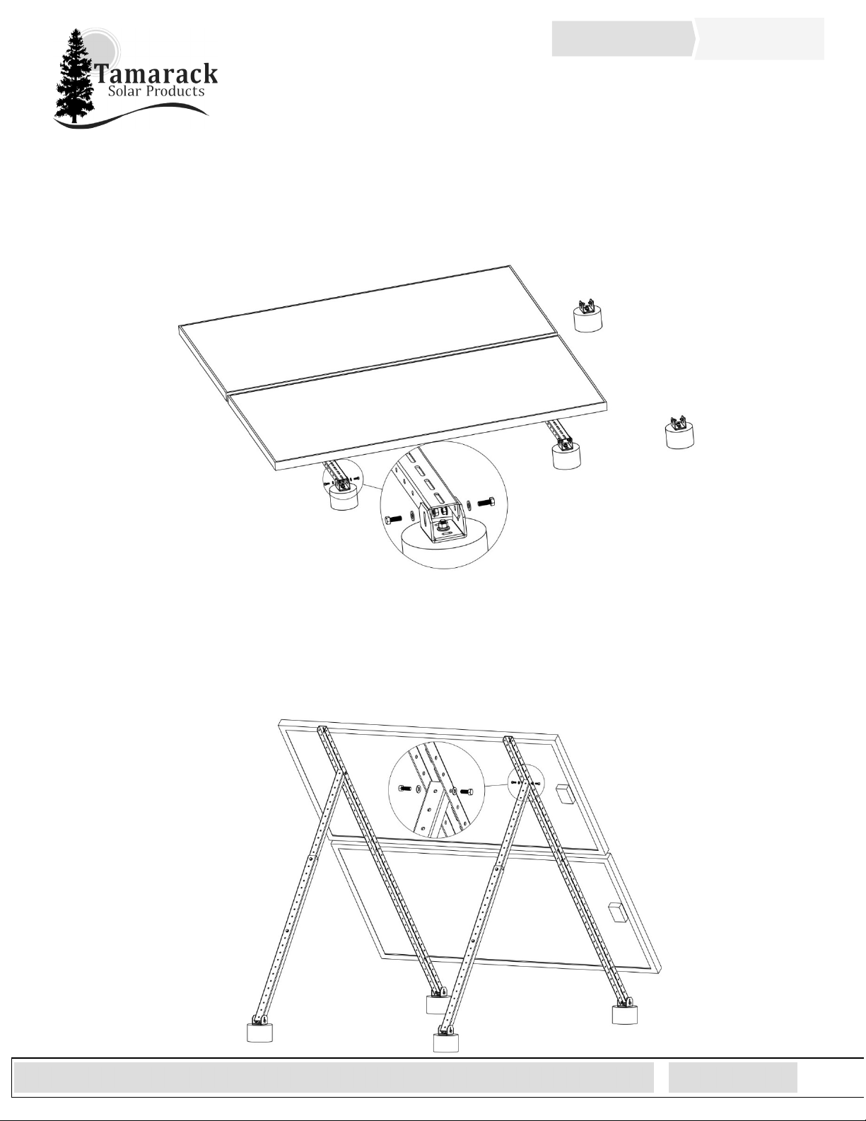
Step 2: Attach Pre Assembled Panel array to footings.
................................................................................9
Step 3: Attach rear braces to panel supports
...............................................................................................9
Step 4: Multi-Mount Intertie Installation
...................................................................................................10
InstallerResponsibility
.................................................................................................................................11
Warranty Information...................................................................................................................................11
Introduction
The Universal Ground/Roof Mount is a simple and universal mounting solution up to 3 solar panels.
With its user-adjustable angle settings, the Ground/Roof Mount can support installations in a wide
range of locations, as a standalone or multiple mounts intertied in rows. Quantities of panels
supported vary by panel widths.
Customer Support
Tamarack Solar makes every effort to ensure your
m
ounting kit is easy to install. If you need
assistance at any point in your installation or have suggestions on how we can improve your
experience, call customer support at 1-800-819-7236 ext 556 or email us at
support@tamaracksolar.com.
Tools Required
Tools that support the following size Hex heads: Torque values listed in the
manual are “dry”, the use of anti-seize lubricant on Stainless hardware is
Recommended (see the torque chart).
1. 7/16” Socket
2. 1/2" Socket

Installation Manual
Ground Roof
Mount Series
su
pp
ort
@
tamaracksolar.com 1-800-819-7236 Ext 556 Pa
g
e 2
Components List
The following parts are included with the GR mounts
Part # Description UNI-GR/90 UNI-GR/130
51-0627-003 Channel Connector 2 2
51-0545-001 Panel Support Channel - 45-inch 4
51-0565-001 Panel Support Channel - 65-inch 4
51-0546-000 Inner Brace Channel - 46-inch 2 2
51-0546-001 Outer Brace Channel - 46-inch 2 2
51-6000-003 U-Foot 4 4
51-6000-004 Backing Plate 4 4
29-5001-100 Mount Assembly Hardware – 5/16-inch 1 1
29-5001-0GR Module Mounting Hardware – ¼-inch 4 4
Inner\Outer Brace channels Channel Connector
Panel support Channel
U-Foot and Backing Plate

Installation Manual
Ground Roof
Mount Series
su
pp
ort
@
tamaracksolar.com 1-800-819-7236 Ext 556 Pa
g
e 3
Pre Assembly
Step 1: Connect Panel Support Channels
A. Slide the 10” connector halfway into the end of the one of the panel support and install the 5/16”
hardware, Torque to 132 in-lbs. repeat with the second panel support to achieve the overall panel
support length
B. UNI-GR/90 uses two 45” panel support channels. UNI-GR/130 uses two 65” panel support channels

Installation Manual
Ground Roof
Mount Series
su
pp
ort
@
tamaracksolar.com 1-800-819-7236 Ext 556 Pa
g
e 4
Step 2: Determine foot spacing
There are many combinations of bolting locations and brace overlap configurations to achieve foot
spacing’s for the angle(s) desired for your location, the following is a process to make that
determination to fit your requirements, or use the general specification chart on page 5.
A.
For the front to rear distance, loosely assemble the A frame section as shown below, adjust the rear leg
brace maintaining the minimum 6” overlap or more (“C”) to support the panels at the desired angle to
the sun and keeping the rear leg within 60° to 90° to the panel supports. With the “A” frame laying on
a flat surface measure the center to center distance between the U-feet to determine the front to rear
spacing for the footing.
B.
Keep the rear brace assembled at the overlap determined in prior operation, preassemble the second
pair and set aside.
C.
For the side-to-side footing of both “A” frames, the center to center spacing is equal to the center-to-
center distance of the mounting holes on the PV module you are using, See mount spacing diagram on
PAGE 5.
D.
If you are installing multiple UNI-GR mounts side-by-side, leave a 1” space between the edges of the
modules on each mount. To determine the spacing between mounting feet, measure the distance from
the short edge of the modules to the mounting hole you are using. The recommended spacing
between mounting feet on adjacent mounts is two times the distance from the edge of the panel to
center of the mounting hole plus 1”. See the diagram in Step 1 of Final Assembly on page 8

Installation Manual
Ground Roof
Mount Series
su
pp
ort
@
tamaracksolar.com 1-800-819-7236 Ext 556 Pa
g
e 5
General specification chart
The tables below are suggested front to back foot spacing “E” with the tilt angles that can set at that
spacing. “A” is module tilt angle from the horizontal, “C” is the overlap of the back leg sections and “D” is the
distance from the top of the module mounting rail to the hole used to connect the back leg. See the
diagrams on Page 4.
UNI-GR/90 UNI-GR/130
"A" ANGLE Û Û Û 36 "A" ANGLE Û Û Û 32
"C" OVERLAP 16" 28 40 44" "C" OVERLAP 10" 22 34 44
"D" DISTANCE 15 15 15 15 "D" DISTANCE 41 41 41 41
"E" FOOT SPACING 78 78 78 78 "E" FOOT SPACING 75 75 75 75
UNI-GR/90 UNI-GR/130
"A" ANGLE 55 Û Û Û 25 "A" ANGLE 45 Û Û 20
"C" OVERLAP 6 12 24 38 44 "C" OVERLAP 8 16 30 44
"D" DISTANCE 15 15 15 15 15 "D" DISTANCE 41 41 41 41
"E" FOOT SPACING 104 104 104 104 104 "E" FOOT SPACING 120 120 120 120

Installation Manual
Ground Roof
Mount Series
su
pp
ort
@
tamaracksolar.com 1-800-819-7236 Ext 556 Pa
g
e 6
Step 3: Foot attaching options
Use Galvanized or Stainless-Steel Hardware
See Suggestions below:

Installation Manual
Ground Roof
Mount Series
su
pp
ort
@
tamaracksolar.com 1-800-819-7236 Ext 556 Pa
g
e 7
Step 4 Attaching PV modules to panel supports
A. Lay the PV Modules face-down on a protected flat surface mounting hole side up.
B. Lay the flat side of the panel support channels across the panels keeping panels and supports
parallel.
C. Align mounting holes on the panels with the slots on the panel supports, allow
Approximately 1/4" to 1” in between PV modules and leave any available left-over support length at
the bottom of the array for ground clearance to allow for vegetation management.
D. Secure with 5/16” hardware and torque to 132 in-lbs. if the mounting holes on the solar panels are
large enough. If the panels have 1/4” or 6 mm holes, use the ¼” hardware in the 29-5000-0GR
mounting hardware kits and torque them to 75 in-lbs.

Installation Manual
Ground Roof
Mount Series
su
pp
ort
@
tamaracksolar.com 1-800-819-7236 Ext 556 Pa
g
e 8
Final Assembly
Step: 1
Attach U-foot to footings
A. Attach the U-foot and backing plate to your footings, align the feet east\west and north\south
and torque 3/8-16 galvanized hardware to 16 ft-Lbs. (Concrete footings shown)
Space between
mounts
Step 2: Attach Preassembled rear braces to footings.
A. Loosely attach the pre-assembled rear brace to the rear footings (pre-assembled from the
prior angle determination step). The “outer leg” is attached to the foot. Lay back away from
the front for next step.

Installation Manual
Ground Roof
Mount Series
su
pp
ort
@
tamaracksolar.com 1-800-819-7236 Ext 556 Pa
g
e 9
Step 3: Attach Pre-Assembled Panel array to footings.
A. Loosely attach one end of the Panel assembly to the U-feet on the footings.
Step 4: Attach rear braces to panel supports
A. Tilt up the array, and the rear braces, and bolt the rear leg into the hole chosen at the distance on
step 2 of “Determine
foot spacing
” operation, or the general spec chart.
B. Torque all locations to 132 in-lbs.

Installation Manual
Ground Roof
Mount Series
su
pp
ort
@
tamaracksolar.com 1-800-819-7236 Ext 556 Pa
g
e 10
OPTIONAL UNI-GR Intertie Installation 51-0520-005
If you are installing 2 or more UNI-GR mounts, you can tie them together to increase stability by
putting one of the UNI-GR intertie kits between each mount. This brace is adjustable from 18.25” to
32” and can be used with solar panels that have mounting holes that at between 7” and 15” from the
end of the modules.
A.
Loosely connect the inner and outer intertie channels with the 5/16” bolt, lock washer, flat
washer, and hex nut.
B.
Place the intertie as shown about midway between the rear brace connection and the end of the
panel support channels, slide the channels out to meet the panel support channels, connect with
the 5/16” hardware, torque to 132 In Lbs 6 places.

Installation Manual
Ground Roof
Mount Series
su
pp
ort
@
tamaracksolar.com 1-800-819-7236 Ext 556 Pa
g
e 11
InstallerResponsibility
The installer is solely responsible for:
i. Complying with all applicable local or national building codes, including any that may supersede this manual.
ii. Ensuring that Tamarack Solar and other products are appropriate for the installation and the installation
environment.
iii. Using only Tamarack Solar parts and installer-supplied parts as specified by Tamarack Solar. Substitution
parts may void the warranty.
iv. Ensuring safe installation of all electrical aspects of the PV array.
v. Ensuring correct and appropriate des.gn parameters are used in determining the design loading used for the
specific installation. Parameters, such as snow loading, wind speed, exposure and topographic factor should
be confirmed with the local building official or a licensed professional engineer.
Warranty Information
Tamarack Solar warrants each Mounting Structure to be free from defects in materials and workmanship for ten (10)
years from the date of first purchase (“Warranty Period”), when installed properly and used for the purpose for which it is
designed, except for the finish, which shall be free from visible peeling, or cracking or chalking under normal atmospheric
conditions for a period of three (3) years, from the earlier of 1) the date the installation of the Product is completed, or 2)
30 days after the purchase of the Product by the original Purchaser (“Finish Warranty”). The Finish Warranty does not
apply to any foreign residue deposited on the finish.
All installations in corrosive atmospheric conditions are excluded. The Finish Warranty is VOID if the practices specified
by AAMA 609 & 610-02 – “Cleaning and Maintenance for Architecturally Finished Aluminum” (www.aamanet.org) are not
followed by Purchaser for Tamarack Solar’s aluminum-based products.
The warranty covers the replacement cost of parts to repair the product to proper working condition. Transportation and
incidental costs associated with warranty items are not reimbursable. The warranty does not cover normal wear, or
damage resulting from misuse, abuse, improper installation, negligence, or accident, or typographical errors in instruction
manuals. The Warranty does not cover any defect that has not been reported in writing to Tamarack Solar within ten (10)
days after discovery of such defect. Furthermore, it does not cover units that have been altered, modified, or repaired
without written authorization from the manufacturer or its authorized representative, or units used in a manner or for a
purpose other than that specified by the manufacturer. Tamarack Solar’s entire liability and Purchaser exclusive remedy,
whether in contract, tort or otherwise, for any claim related to or arising out of breach of the warranty covering the
Mounting Structures shall be correction of defects by repair, replacement, or credit, at Tamarack Solar’s discretion.
Refurbished Mounting Structures may be used to repair or replace the Mounting Structures
Tamarack Solar shall have no liability for any injuries or damages to persons or property resulting from any cause,
whatsoever, or any claims or demands brought against Tamarack Solar by Purchaser, any employee of Purchaser, client of
Purchaser, end-user of the Product or other party, even if Tamarack Solar has been advised of the possibility of such claims
or demands (collectively, “Third Party Claims”). This limitation applies to all materials provided by Tamarack Solar during
and after the Warranty Period.
This manual suits for next models
1
Table of contents
Other Tamarack Solar Solar Panel manuals