4516 112 Ave S.E. Calgary, Alberta • Tel: (403) 279 0020 • Fax: (403) 279 0747
www.tamashydronic.com Page 2
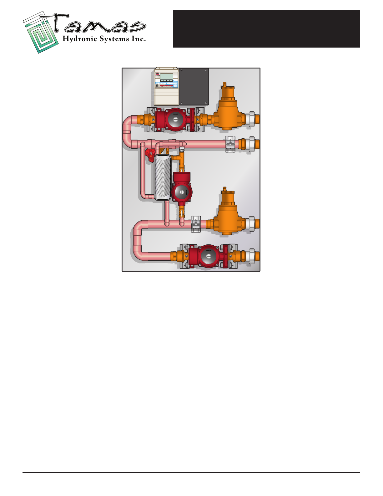
Tamas Hydronic Panels
Snow Melt Series
Table of Contents
Introduction................................................................................................................................ 3
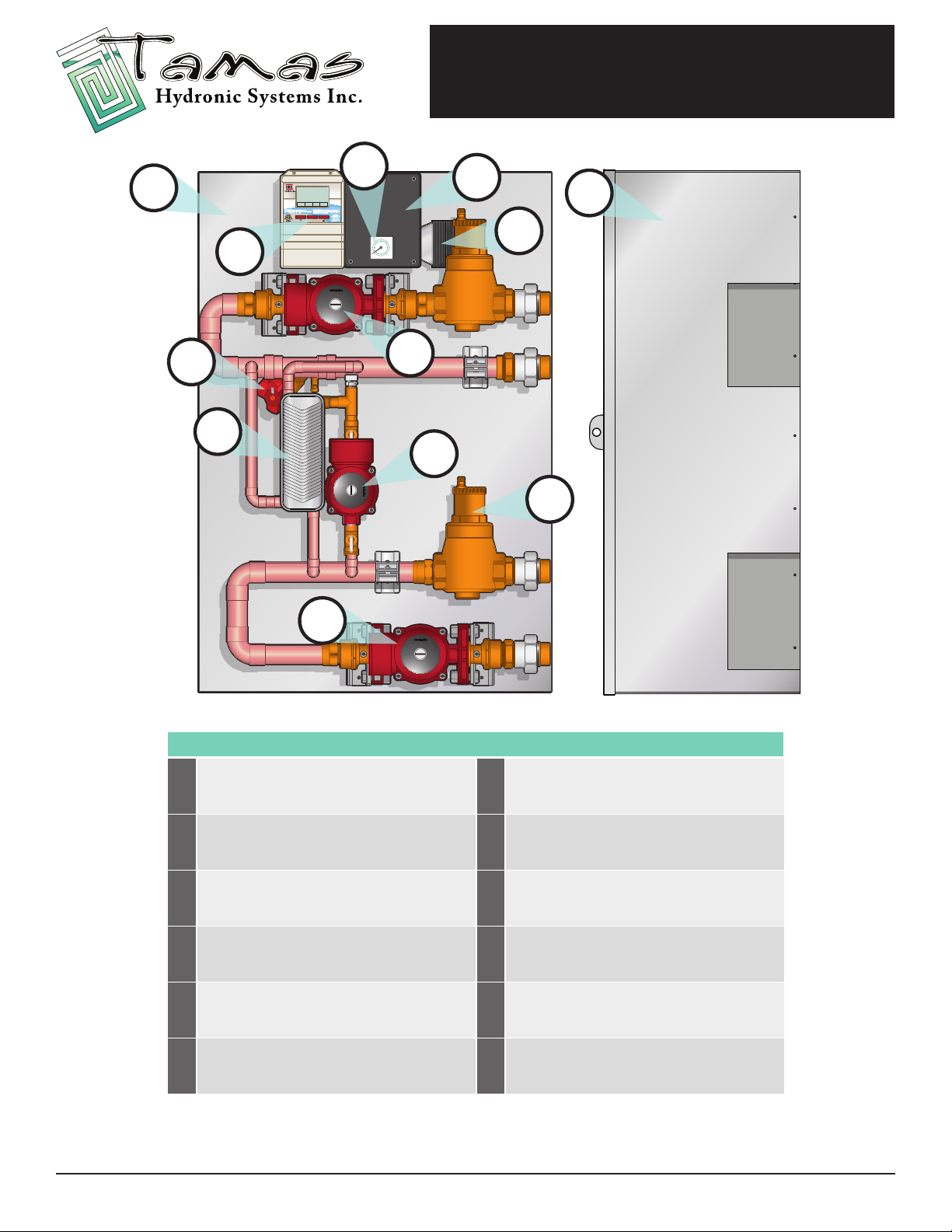
Components................................................................................................................................4
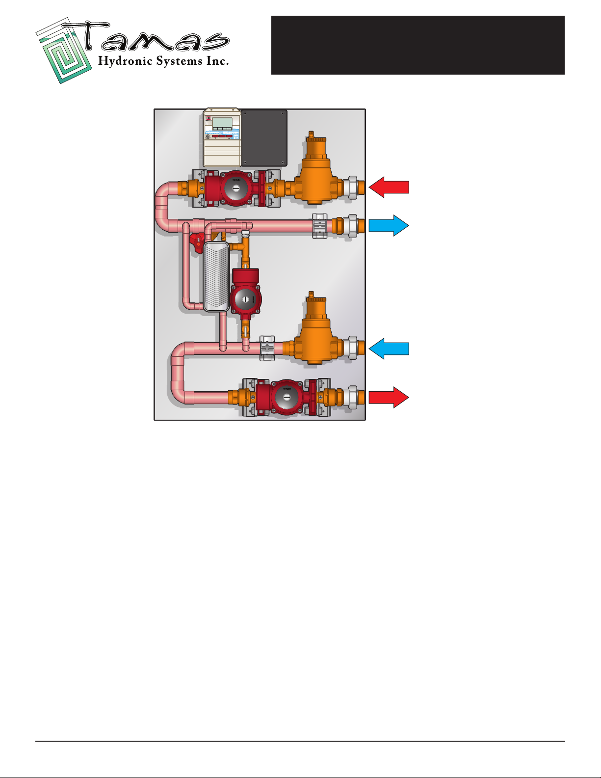
Operation.................................................................................................................................... 5
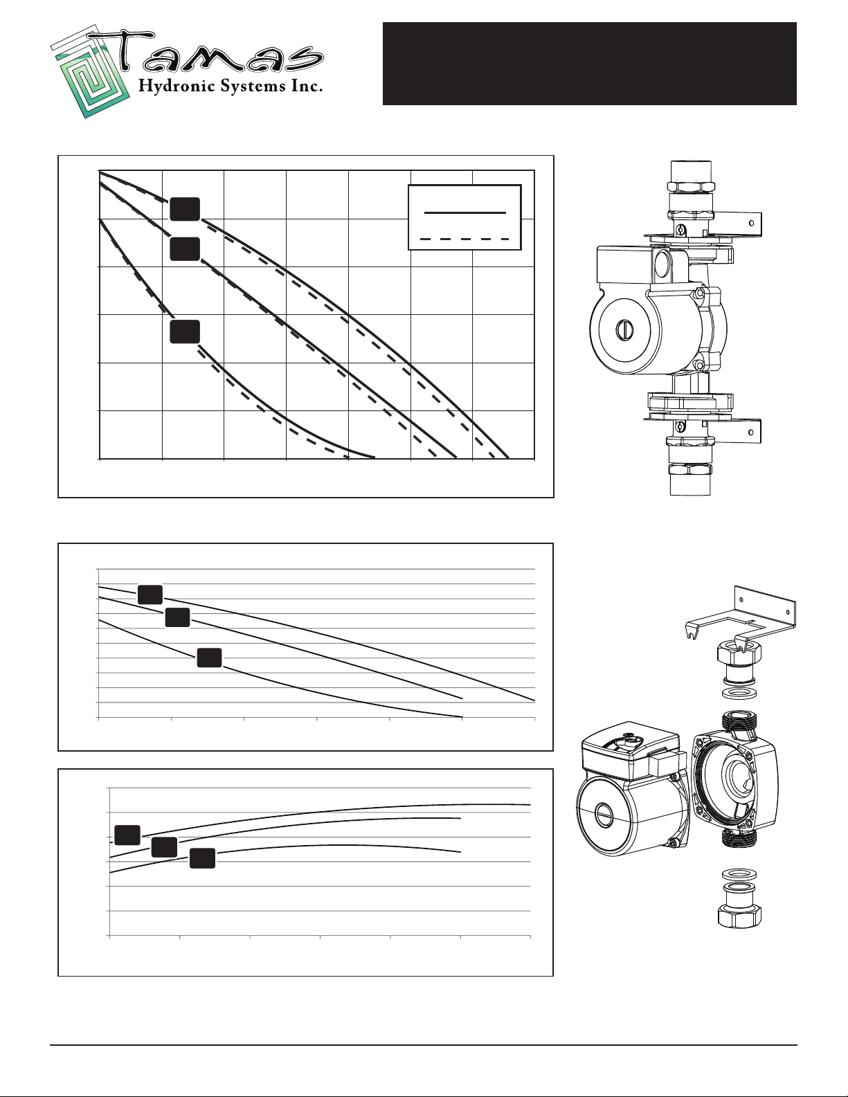
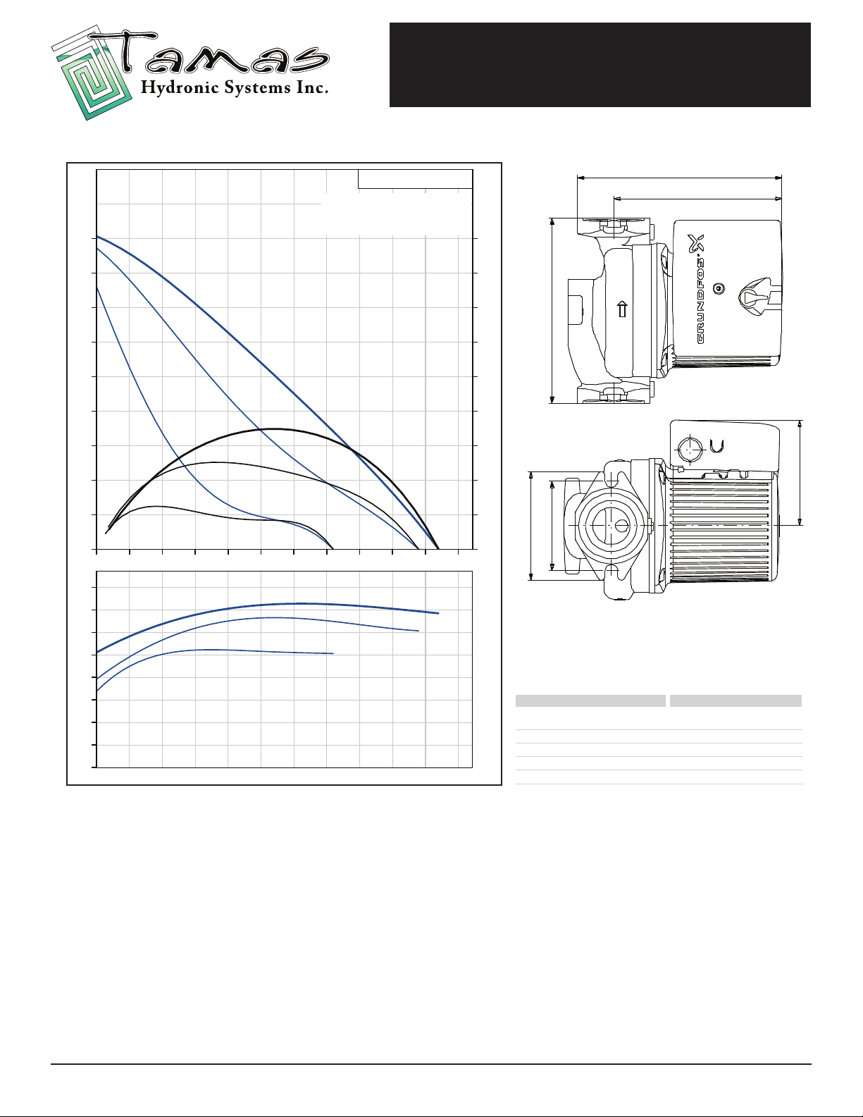
Technical Data............................................................................................................................ 6-9
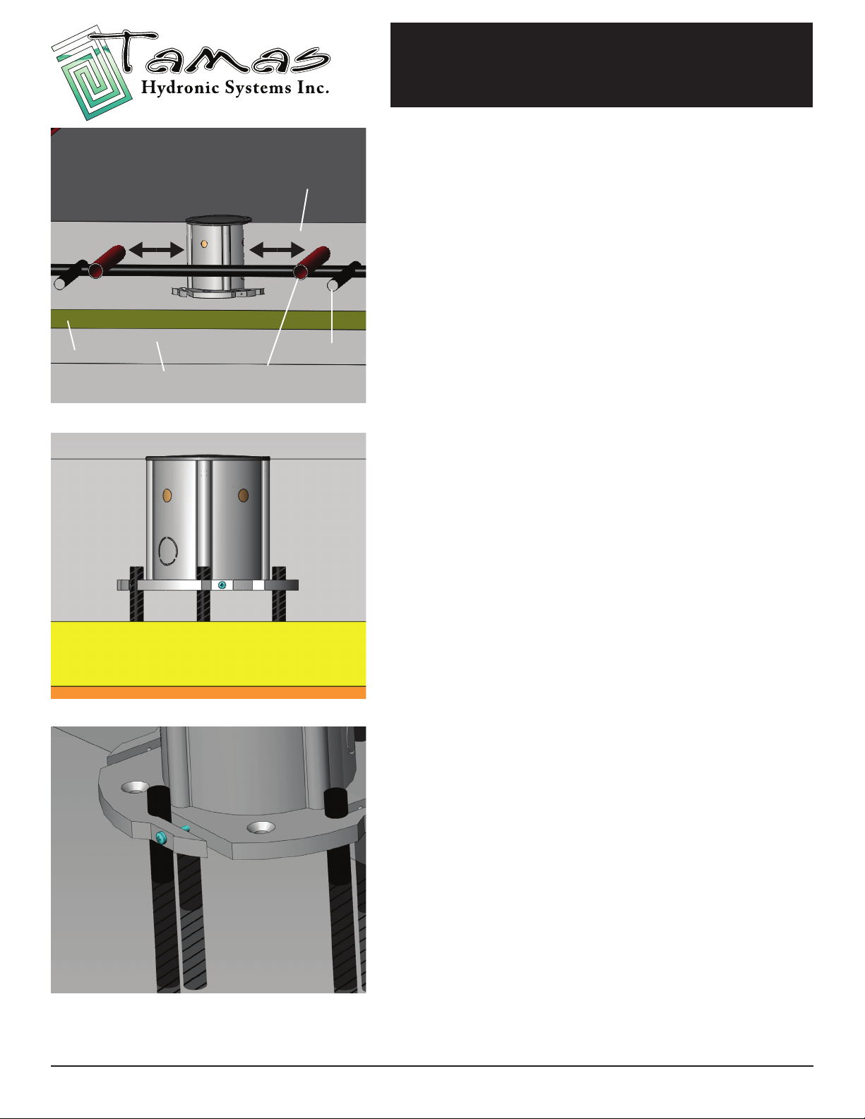
Snow Sensor Installation.......................................................................................................... 10-11
Wiring...........................................................................................................................................12
Modular Expansion Panels.......................................................................................................13
Warranty......................................................................................................................................14
* Note:
The following parts lists and applicaon drawings are general samplings. Each panel conguraon dictates the required components, including
pump type. See the Technical Data secon of the manual for specic informaon on each part in your parcular variaon of the Tamas I.B.C. Boiler
Board.
This User Guide is Applicable to:
Tamas Snow Melt Panels
T-SM-HBX-50HX 50, 000 BTU Snow Melt Panel with HBX SNO-0550, SNO-0110, SNO-0111
T-SM-HBX-100HX 100, 000 BTU Snow Melt Panel with HBX SNO-0550, SNO-0110, SNO-0111
T-SM-HBX-150HX 150, 000 BTU Snow Melt Panel with HBX SNO-0550, SNO-0110, SNO-0111
T-SM-HBX-200HX 200, 000 BTU Snow Melt Panel with HBX SNO-0550, SNO-0110, SNO-0111
T-SM-HBX-250HX 250, 000 BTU Snow Melt Panel with HBX SNO-0550, SNO-0110, SNO-0111
T-SM-HBX-300HX 300, 000 BTU Snow Melt Panel with HBX SNO-0550, SNO-0110, SNO-0111
T-SM-HBX-350HX 350, 000 BTU Snow Melt Panel with HBX SNO-0550, SNO-0110, SNO-0111
Safety Procautions
Only suitably qualied individuals with formal training in electrical controls and hydronic systems
should aempt the installaon of this panel. Incorrect installaon will aect the warranty provided
with this panel.
During installaon and operaon, avoid injury from touching the hot surface of the pipe.
Please follow all warning signs on the panel for your own safety while dealing with the installaon
and service of this panel.