tams elektronik WIB-33.2 User manual

tams elektronik
Manual
WIB-33.2
Carriage lighting
with integrated function decoder
Colour of lighting: warm white
Item no. 53-01340
tam elektronik
n n n
Verion 2016
with OSRAM LED
Duri E5

tams elektronik
Engli h WIB-33.2
Table of content
1. Getting tarted............................................................................3
2. Safety in truction .......................................................................4
3. Safe and correct oldering...........................................................5
4. Operation overview.....................................................................6
5. Technical pecification ...............................................................9
6. Mounting the carriage lighting....................................................10
6.1. Overall view......................................................................10
6.2. Connection to the power upply.........................................11
6.3. Connecting bridging capacitor ...........................................11
6.4. Connecting a light depending re i tor.................................11
6.5. Connecting LED to the output AUX2..................................12
6.6. Connecting auxiliary device to the output AUX1 and AUX3 12
6.7. Connecting PCB ection 2...................................................12
6.8. Setting the LED ´ brightne ..............................................13
6.9. Fixing the carriage lighting.................................................13
7. Programming the function decoder.............................................13
8. Configuration variable and regi ter ..........................................14
9. Pre et .....................................................................................19
10. Check li t for trouble hooting.....................................................20
11. Guarantee bond........................................................................21
12. EU declaration of conformity.....................................................21
13. Declaration conforming to the WEEE directive...........................21
© 11/2016 Tam Elektronik GmbH
All right re erved. No part of thi publication may be reproduced or
tran mitted in any form or by any mean , electronic or mechanical,
including photocopying, without prior permi ion in writing from Tam
Elektronik GmbH.
Subject to technical modification.
Remark: RailCom® i the regi tered trademark of the Lenz Elektronik
GmbH, Hüttenberg traße 29, D-35398 Gießen. To increa e the text´
readability we have refrained from refering to thi point in each
in tance.
The asterisks **
Thi manual mention the following companie :
Gebr. MÄRKLIN** & Cie. GmbH | Po tfach 8 60 | D-73008 Göppingen
Page 2

tams elektronik
!
WIB-33.2 Engli h
1. Getting tarted
How to use this manual
Thi manual give tep-by- tep in truction for afe and correct fitting and
connecting of the module, and operation. Before you tart, we advi e you
to read the whole manual, particularly the chapter on afety in truction
and the checkli t for trouble hooting. You will then know where to take
care and how to prevent mi take which take a lot of effort to correct.
Keep thi manual afely o that you can olve problem in the future. If
you pa the module on to another per on, plea e pa on the manual
with it.
Intended use
The carriage ligthing are de igned to be operated according to the
in truction in thi manual in model building and with model railway .
Any other u e i inappropriate and invalidate any guarantee .
The carriage ligthing hould not be mounted by children under the age
of 14.
Reading, under tanding and following the in truction in thi manual
are mandatory for the u er.
Caution:
Integrated circuit (IC ) are in erted on the module. They are
en itive to tatic electricity. Do not touch component without fir t
di charging your elf. Touching a radiator or other grounded metal part
will di charge you.
Checking the package contents
Plea e make ure that your package contain :
one or ix carriage lighting
one or ix light dependent re i tor
two or twelve red LED
a CD (containing the manual and further information)
Required materials
For connecting the carriage ligthing you need:
an electronic oldering iron (max. 30 Watt) or a regulated oldering
iron with a fine tip and a oldering iron tand,
a tip-cleaning ponge,
a heat-re i tant mat,
a mall ide cutter and wire tripper,
a nece ary a pair of tweezer and long no e plier ,
electronic tin older (0,5 mm. Diameter),
wire (diameter: > 0,05 mm² for all connection ).
If you intend to horten the module: a mall metal aw.
If nece ary, for the external power upply of the LED :
an electrolytic capacitor with a voltage u taining capability of > 16 V or
two goldcap with a voltage u taining capability of > 5,5 V.
If nece ary, for the external power upply of the decoder´ function
output : an electrolytic capacitor with a voltage u taining capability of
> 25 V or > 35 V (when connecting it to analogue a.c. voltage).
If nece ary, a rectifier ( ee ection 6, connecting part 2).
Page 3

tams elektronik
!
Engli h WIB-33.2
2. Safety in truction
Mechanical hazards
Cut wire can have harp end and can cau e eriou injurie . Watch
out for harp edge when you pick up the PCB.
Vi ibly damaged part can cau e unpredictable danger. Do not u e
damaged part : recycle and replace them with new one .
Electrical hazards
Touching powered, live component ,
touching conducting component which are live due to malfunction,
hort circuit and connecting the circuit to another voltage than
pecified,
impermi ibly high humidity and conden ation build up
can cau e eriou injury due to electrical hock. Take the following
precaution to prevent thi danger:
Never perform wiring on a powered module.
Mounting hould only be done in clo ed, clean, dry room . Beware of
humidity.
Only u e low power for thi module a de cribed in thi manual and
only u e certified tran former .
Connect tran former and oldering iron only in approved main
ocket in talled by an authori ed electrician.
Ob erve cable diameter requirement .
After conden ation build up, allow a minimum of 2 hour for
di per ion.
U e only original pare part if you have to repair the kit or the
ready-built module.
ire risk
Touching flammable material with a hot oldering iron can cau e fire,
which can re ult in injury or death through burn or uffocation.
Connect your oldering iron or oldering tation only when actually
needed. Alway keep the oldering iron away from inflammable
material . U e a uitable oldering iron tand. Never leave a hot
oldering iron or tation unattended.
Thermal danger
A hot oldering iron or liquid older accidentally touching your kin can
cau e kin burn . A a precaution:
u e a heat-re i tant mat during oldering,
alway put the hot oldering iron in the oldering iron tand,
point the oldering iron tip carefully when oldering, and
remove liquid older with a thick wet rag or wet ponge from the
oldering tip.
Dangerous environments
A working area that i too mall or cramped i un uitable and can cau e
accident , fire and injury. Prevent thi by working in a clean, dry room
with enough freedom of movement.
Other dangers
Children can cau e any of the accident mentioned above becau e they
are inattentive and not re pon ible enough. Children under the age of
14 hould not be allowed to mount the module .
Caution:
Little children can wallow mall component with harp edge , with
fatal re ult ! Do not allow component to reach mall children.
In chool , training centre , club and work hop , mounting and
operation mu t be upervi ed by qualified per onnel.
In indu trial in titution , health and afety regulation applying to
electronic work mu t be adhered to.
Page 4

tams elektronik
!
WIB-33.2 Engli h
3. Safe and correct oldering
Caution:
Incorrect oldering can cau e danger through fire and heat. Avoid
the e danger by reading and following the direction given in the
chapter Safety instructions.
U e a mall oldering iron with max. 30 Watt. Keep the oldering tip
clean o the heat of the oldering iron i applied to the older point
effectively.
Only u e electronic tin older with flux.
When oldering electronic circuit never u e oldering-water or
oldering grea e. They contain acid that can corrode component
and copper track .
Solder quickly: holding the iron on the joint longer than nece ary can
de troy component and can damage copper track or oldering eye .
Apply the oldering tip to the oldering pot in uch a way that the
wire and the oldering eye are heated at the ame time.
Simultaneou ly add older (not too much). A oon a the older
become liquid take it away. Hold the oldering tip at the pot for a
few econd o that the older flow into the joint, then remove the
oldering iron.
The joint hould be held till for about 5 econd after oldering.
To make a good oldering joint you hould u e a clean and
unoxidi ed oldering tip. Clean the oldering tip with a damp piece of
cloth, a damp ponge or a piece of ilicon cloth.
After oldering check (preferably with a magnifying gla ) track for
accidental older bridge and hort circuit . Thi would cau e faulty
operation or, in the wor t ca e, permanent damage. You can remove
exce older by putting a clean oldering tip on the pot. The older
will become liquid again and flow from the oldering pot to the
oldering tip.
Page 5

tams elektronik
Engli h WIB-33.2
4. Operation overview
Possibilities of use
The carriage lighting WIB-33.2 can be u ed in digital layout driven in
DCC or Motorola format a well a in analogue model railroad layout .
For the power upply digital boo ter or analogue a.c. or d.c.
tran former can be u ed.
Design of the PCB
The carriage lighting WIB-33.2 have in erted 8 warm white LED . On
the PCB (or after hortening the PCB, on the remaining ection 1) are
apart from the LED :
RailCom compatible function decoder for DCC and Motorola format,
three witchable output for upplementary load (e.g. back lighting,
additional lighting, electric coupling ),
integrated moothing capacitor a a flickering protection,
connecting point for two external bridging capacitor to upply the
LED and the function output of the decoder.
Section 1
with function decoder
Section 2
without function decoder
length [mm]
appr.
number of
LED
length [mm]
appr.
number of
LED
240 8 0 0
210 7 30 1
176 6 64 2
142 5 98 3
117 4 123 4
75 3 165 5
The length of the PCB a well a number and layout of the LED
corre pond to the carriage lighting WIB-13.2. Thu the (analogue)
carriage lighting WIB-13.2 i uitable e pecially for combining with the
lighting of the 30 erie in a block train.
Driving in digital Operation
There i a function decoder integrated on the PCB, that can operate
with and automatically recogni e both DCC or Motorola format .
The number of addre e i dependant on the format being u ed.
Motorola-Format: 255 addre e
DCC- Format: 127 Ba i -addre e or 10.239 extended addre e .
In the DCC format the decoder can be driven in all peed level (14, 28
or 128).
Programming the decoder i done in DCC format by etting the
configuration variable and in Motorola format through the regi ter .
Switching the functions in digital mode
The LED on the PCB, the three function output of the decoder and
further function are witched via the function F0 to F15 in DCC format.
In Motorola format the function key F0 to F4 are available. The
function F5 to F9 can be witched via the function key F1 to F4 and
F0 by a igning them to a econd addre . The function F10 to F15
are not available in Motorola format.
The a ignment of the function key to
the LED ,
the function output of the decoder,
further function ( witching on and off the orientation light and the
dimmer witch)
can be done freely. It i po ible to a ign everal function key to one
LED, one function output or one function.
Page 6

tams elektronik
WIB-33.2 Engli h
Operation in analogue mode
The carriage lighting WIB-33.2 can al o be u ed in analogue model
railway layout . When putting the vehicle on the rail the decoder
recognize automatically if it i run in analogue or digital mode and et
the corre ponding operation mode. The automatic recognition of the
analogue mode can be witched off.
Switching the LED and the function output on or off i not po ible in
analogue mode. They can be programmed o that they are either
witched on or off in analogue mode. The effect et for the output
are active in analogue mode a well.
In analogue layout upplied with d.c. voltage, the function output
witched with F0 are witched on and off according to the direction of
travel. Thi i not po ible in analogue a.c. layout a the decoder doe
not recognize the impul e for changing the direction of travel.
Activating the LEDs
The eight LED can be witched on and off individually, in group or
corporately. By programming the decoder accordingly you can
et the LED ´ brightne individually for each LED,
witch the LED according to the direction of travel,
imulate fluore cent tube when witching on the LED ,
et the duration of the witching on of the fluore cent tube
imulation until reaching a con tant light and a defective fluore cent
tube individually for each LED.
You can witch from tandard lighting to orientation light with a
function key (e.g. for holded carriage or leeping car ). The orientation
light´ brightne i et corporately for all LED .
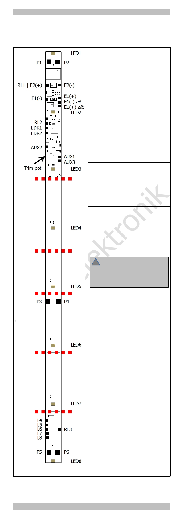
In tead of programming the LED ´ brightne with a digital control unit
you can et it with a trim-pot (corporately for all LED ). The brightne
programmed via CV or regi ter remain active, the etting at the trim-
pot only alter the brightne with a factor valid for all LED .
Activating the addtional function outputs
There are three output for external load on the PCB controlled by the
integrated decoder. The output AUX2 i de igned for the connection of
LED for the back lighting. The nece ary erie re i tor are integrated
on the PCB.
The two output AUX1 and AUX3 are available e.g. for the connection
of additional lighting (e.g. in the driver´ cabin or in the toilet cabin) or
electric coupling . Their maximum current i 300 mA.
It i po iblie to witch all output dependent on the direction of travel
and to dim them.
Be ide , the two output AUX 1 and AUX 3 provide:
Kick function for pecial type of electric coupling needing a
reduction of the connected voltage after the witching operation in
order to protect the coupling.
Random witch witching on and off the output in irregular interval
(e.g. for the lighting of a toilet cabin).
Connecting a light dependent resistor
When a light dependent re i tor i connected, the LED and the
decoder´ function output can be witched on and off automatically
depending on the urrounding lighting. The en ivity i et via CV or
regi ter . You can activate the dim witch with a function key.
The dim witch effect only tho e output witched on. A oon a the
output have been witched off by the dim witch they cannot be
witched on with a function key. In thi ca e the dim witch ha to be
deactivated fir t.
With the initial etting the LED are witched on a oon a the
urrounding lighting under-run the et limit value. It i po ible to
invert thi functionality, e.g. in order to automatically witch off the
lighting in a hadow tation.
lickering protection
An integrated moothing capacitor upplie the LED when hort
current interruption occur, which prevent the lighting from flickering
when point or mudge on the rail are cro ed. In ca e the integrated
moothing capacitor i not ufficient, you can connect an additional
external bridging capacitor with a minimal voltage u taining capability
Page 7

tams elektronik
Engli h WIB-33.2
of 16 V or two goldcap with a minimal voltage u taining capability of
5,5 V.
In order to upply the three function output of the decoder you can
connect a econd additional external bridging capacitor. It i not
po ible to u e goldcap here, a the minimal voltage u taining
capability i 25 V or 35 V (when connecting the PCB to analogue a.c.
voltage).
eedback with RailCom
RailCom i a log for bi-directional communication in digital model
railway layout controlled in DCC-format. It allow e.g. the feedback of
the addre and the CV value from the decoder to the digital control
unit or to pecial receiver ( o-called detector ). The decoder mu t be
de igned to end the RailCom me age .
When o programmed, the integrated function decoder end
(continuou ly) the (ba ic, extended or con i t) addre to the detector
( o-called RailCom broadca t datagramm) and tran fer a CV me age
after a DCC CV read-out command.
Sending RailCom me age i only po ible in layout with a DCC ignal
on the rail . That i the rea on why it i not po ible to u e the
RailCom-function in a pure Motorola environment, but only when at
lea t one other locomotive or function decoder on the layout i
controlled in DCC format.
Page 8

tams elektronik
WIB-33.2 Engli h
5. Technical pecification
Data format DCC, Motorola
Adre range MM: 1020
DCC: 2040
Hint: The adre range to be u ed al o
depend from the control unit.
Speed level (DCC-
Format)
14, 28 or 128
Feedback log RailCom
Supply voltage Digital voltage of the central unit
or analogue d.c. or a.c. voltage
Minimum upply voltage
approx.
7 V (yellow LED )
8 V (white LED )
Maximum upply voltage 24 Volt
Current con umption at
maximum brightne
(without connected load
approx.
50 mA
Number of output 3
Maximum current of the
function output :
AUX 1 and 3
AUX 2
300 mA each
20 mA
Connection for bridging
capacitor / gold cap
for the upply of the
LED
1
electrolytic capacitor > 100 µF / > 16 V
or
gold cap > 5,5 V
Connection for bridging
capacitor
for the upply of the
integrated decoder´
output
1
electrolytic capacitor > 100 µF / > 25 V
with connection to analogue a.c. voltage:
electrolytic capacitor > 100 µF / > 35 V
LED 8 x OSRAM Duri E5 (warm white)
dimen ion : 5,6 x 3,0 x 0,6 mm
colour temperature: 3.000 K
luminou inten ity: 15.000... 19.400 mcd
angle of reflected beam: 120°
Protected to IP 00
Ambient temperature in
u e
0 ... +60 °C
Ambient temperature in
torage
-10 ... +80 °C
Comparative humidity
allowed
max. 85 %
Dimen ion of the PCB
approx.
9 x 240 mm
Weight of the PCB
approx.
6 g
Page 9

tams elektronik
!
!
Engli h WIB-33.2
6. Mounting the carriage lighting
6.1. Overall view
P1 …
P6
power upply
E(+)
E(-)
external bridging
capacitor
AUX1
AUX3
decoder output
max. current: 300 mA
AUX2 decoder output for
therconnection of LED
(back lighting)
max. current: 20 mA
RL1
RL2
return conductor for
decoder output
AUX1 and AUX3
RL2 return conductor for
decoder output AUX2
LDR1
LDR2
light depending re i tor
L4 ...
L8
wwitching input for
LED4 … LED8
(with eparate connection
of ection 2)
RL3 return conductor for
L4 … L8
Shortening the carriage
lighting
You can divide or horten the print
at the marked pot !
Caution:
Pay attention not to damage the
connection pad or the part on
the PCB when awing.
After hortening the PCB you get :
Section 1
with integrated function
decoder, with integrated
moothing capacitor,
with connecting point for
external bridging capacitor and
light dependent re i tor (LDR)
Section 2
without integrated function
decoder,
without integrated moothing
capacitor,
without connecting point for
external bridging capacitor and
light dependent re i tor (LDR)
Page 10

tams elektronik
!
WIB-33.2 Engli h
6.2. Connection to the power
upply
Solder the connecting wire for the
power upply to the connecting point
P1, P3 or P5 (from the left rail) and the
connecting point P2, P4 or P6 (from
the right rail).
You can loop through the power upply
from one PCB to the next and thu
upply everal carriage lighting from
one current ource.
Caution:
When u ing power tran mi ing
coupling pay attention not to exceed
the maximum current of the coupling !
6.3. Connecting bridging capacitor
In order to bridge currentle ection you can connect external
bridging capacitor to the PCB ( ection 1).
For the upply of
the LED : an electrolytic capacitor with a voltage u taining
capability of > 16 V or two goldcap with a voltage u taining
capability of > 5,5 V. Solder them to the connecting point E1(+)
and E1(-).
Load connected to the output of the integrated function decoder:
an electrolytic capacitor with a voltage u taining capability of
> 25 V or, when connecting it to analogue a.c. voltage, > 35 V.
Solder it to the connecting point E2(+) and E2(-).
Choo e an electrolytic capacitor or a goldcap with a
capacity a high a po ible. A the hou ing of
electrolytic capacitor and goldcap are bigger
when the capacity i higher, the maximum capacity
i limited by the pace available to mount the
capacitor.
6.4. Connecting a light depending
re i tor
You can witch on and off the LED and the
decoder´ function output automatically
depending on the urrounding lighting when
mounting a light depending re i tor to the
connecting point LDR1 and LDR2.
Page 11

tams elektronik
!
!
!
Engli h WIB-33.2
6.5. Connecting LED to the output AUX2
The output AUX2 ha been de igned for the
connection of LED for the back lighting. The
maximum current i 20 mA. The nece ary erie
re i tor are integrated on the PCB. Solder the
LED to the connecting point AUX2 and RL2.
Caution:
Do not connect electric bulb to the output AUX2!
The e have normally a current of more than 20
mA. The output will be damaged when etting-up
operation.
6.6. Connecting auxiliary device to the
output AUX1 and AUX3
Before connecting additional lighting, coupling or
other auxiliary device to the output AUX1 and
AUX3, check if their current i below the maximum
permi ible value of 300 mA. If connecting device
with a higher current to the PCB, the output will be
damaged in the etting-up operation.
Di connect any exi ting diode in the lead to the
lamp . If the lamp or the acce ory i already
connected to vehicle ground, you have to connect it
to the output only. If not, connect the econd ide
of the acce ory to the return conductor of the
decoder (point RL1).
Caution:
If you connect the acce orie to the return conductor for all function
(point RL1), the acce orie mu t be in ulated. The acce orie hould
not make contact with metal part of the vehicle. Po ible hort circuit!
The module will be damaged in operation.
Caution:
The return conductor for all function (point RL1) mu t under no
circum tance be connected to vehicle ground. Po ible hort circuit!
The module will be damaged in operation.
6.7. Connecting PCB ection 2
You can u e ection 2
of the PCB you have
awed off a a LED
PCB. Either connect it
to the output of a
locomotive or function
decoder (e.g. the
integrated function
decoder of ection 1)
and witch the LED
digitally or connect it
directly to an analogue
power upply.
The five connecting point L4 to L8 are a igned to the LED 4 to 8 on
the PCB. When connecting the connecting point eparately to the
output of a decoder you can activate each of the LED eparately in
digital operation.
Connect the connecting point RL3 to the return conductor of the
decoder or to the analogue power upply. When u ing the PCB in
analogue layout you have to mount a rectifier.
Page 12

tams elektronik
WIB-33.2 Engli h
6.8. Setting the LED ´ brightne
In tead of programming with a digital control unit you can et the LED ´
brightne via a trim-pot ( ee digram in ection 6.1). For etting the
trim-pot u e a mall crew-driver.
The brightne programmed via CV or regi ter remain active, the
etting at the trim-pot only alter the brightne with a factor valid for
all LED .
6.9. Fixing the carriage lighting
After completing the connection , ecure the lighting in place (eg. with
double ided adhe ive tape).
7. Programming the function decoder
You can program the integrated function decoder with a digital control
unit.
In DCC format: via configuration variable (CV ) or main track
programming. With DCC control unit allowing only regi ter
programming you can et the regi ter 1 and 5 (corre ponding CV#1
and CV#29) only.
In Motorola format: via regi ter .
Plea e note: When programming the decoder, there hould be
mounted no buffer capacitor or goldcap to E1 or E2, otherwi e
problem can occur (e.g. error me age ).
Programming with DCC central units
See the chapter in the manual of your central unit where the byte wi e
programming of configuration variable (CV ) i explained.
Programming with Motorola central units
Plea e note: If you u e a central unit for both DCC and Motorola format
it i recommended to program the decoder in the DCC format. After
having fini hed programming the decoder it i po ible to control it in
Motorola format a well.
Put the vehicle on a track oval or a track ection connected to the
central unit’ track output (not to the connection for the programming
track). Make ure no other vehicle than the one you intend to program
i et on the track a the decoder in ide thi vehicle might be
programmed a well.
During the programming operation the LED how, which input the
decoder expect :
LED fla h LED top to fla h
Number of the regi ter to be
programmed
Value of the regi ter to be
programmed
Starting
the programming mode Programming the decoder
1. Switch on the central unit or
perform a re et at the central
unit (pu hing " top" and "go").
2. Set the current decoder
addre (default value: 3) or the
addre "80".
3. Set all function to "off".
4. Pu h button " top"
à witch off the track voltage.
5. Operate the direction witch
and hold it in that po ition.
Pu h the button "go" at once.
6. A oon a the LED fla h,
relea e the direction witch.
1. Enter the number of the
regi ter a a Motorola-addre .
If nece ary: with a leading "0".
2. Operate the direction witch.
à LED top to fla h.
3. Enter the value you want to
et into the regi ter
(a Motorola-addre ).
4. Operate the direction witch.
à LED tart to fla h.
Repeat tep 1 – 4
for all regi ter .
Pu h button " top".
à Programming mode à End of programming mode
Page 13

tams elektronik
Engli h WIB-33.2
Programming with the Central Station and the Mobile Station
With the Central Station or the Mobile Station of Märklin* you can
program the regi ter , but the value to be et i limited to 80. Select
the article no. 29750 from the locomotive databa e and program the
decoder a de cribed for thi article in the Central Station´ or Mobile
Station´ manual.
Programming with the CV-Navi
In tead of programming the configuration variable or regi ter of the
decoder u ing the digital central unit, you can u e the free oftware CV-
Navi. You will find the free download under:
www.tam -online.de
8. Configuration variable and regi ter
The following li t how all configuration variable (for the DCC format)
and regi ter (for the Motorola format), that can be et for the
integrated function decoder.
In the li t you will find in the column "CV-no." the number of the
configuration value for programming in DCC format and in the column
"Reg.-no." the number of the regi ter for programming in Motorola
format. The default are tho e value et in the tate of delivery and
after a re et.
If you do not want to program all configuration variable or regi ter
individually you can fall back on different pre et ( ee CV#130 and
ection 9.)
Plea e note: With variable de tined to et everal parameter , the input
value ha to be calculated by adding the numerical value a igned to the
de ired parameter .
Setting the address
Name of CV /
Regi ter
CV-
no.
Reg.
no.
Input value
(Default)
Remark and Tip
Setting
Ba ic addre 1 01 1 ... 255
(3)
Range of value in
DCC format: 1 ... 127
MM format: 1 ... 255
Tip: If a value higher than 127 i et for the ba ic addre and the u e of extended addre e
in CV#29 i et to off, the decoder doe not react to ignal in DCC format!
Extended
addre
17 06 192 ... 255
(192)
Only for DCC format. Mo t
central unit permit entering
extended addre e directly.
The CV # 17, 18 and 29 are
et automatically to the
proper value .
18 07 0 ... 255
(255)
Con i tadre e 19 08 1 ... 127
(0)
= 2nd adre
In DCC format only!
2nd Motorola
addre
114 39 1 ... 255
(4)
= Addre needed to witch
additional function in
Motorola format. The
function key F5 to F8 are
reached via the function
key F1 to F4, the function
key F9 via the function key
F0.
Information / Read only
Name of CV /
Regi ter
CV-
no.
Reg.
no.
Input value
(Default)
Remark and Tip
Setting
Ver ion 7 --- --- Read only in DCC format!
Manufacturer 8 --- (62) Read only in DCC format!
Page 14

tams elektronik
WIB-33.2 Engli h
Auxiliary functions
Name of CV /
Regi ter
CV-
no.
Reg.
no.
Input value
(Default)
Remark and Tip
Setting
Re et 8
03 0 ... 255 Any input value re tore the
etting in tate of delivery.
Basic settings
Name of CV /
Regi ter
CV-
no.
Reg.
no.
Input value
(Default)
Remark and Tip
Setting
Configuration
data 1
29 10 0 ... 64 (14) Direction "Standard" 0
Rever e direction 1
14 peed level 0
28 or 128 peed level 2
Analogue recognition off 0
Analogue recognition on 4
RailCom off 0
RailCom on 8
Ba ic addre e 0
Not for MM mode: Extended addre e 32
Factory etting : Direction of travel = "Standard". 28 or 128 peed level . Automatic analogue
recognition = "on". RailCom "on". Ba ic addre e .
Example: CV#29 = 0. à Direction = "Standard". 14 peed level . Automatic analogue
recognition = "off". RailCom = "off". Ba ic addre e .
Example: CV#29 = 46. à Direction = "Standard". 28 or 128 peed level in DCC-mode.
RailCom = "on". Automatic analogue recognition = "on". Extended Addre e .
Tip: If the u e of extended addre e i activated in CV#29, the decoder doe not react to
ignal in Motorola format!
Settings for analogue mode
Name of CV /
Regi ter
CV-
no.
Reg.
no.
Input value
(Default)
Remark and Tip
Setting
unction
active in
analogue
mode
(only for F1 to
F8, not for F9
to F12)
13 05 0 ... 255 (15) F1 on 1
F2 on 2
F3 on 4
F4 on 8
F5 on 16
F6 on 32
F7 on 64
F8 on 128
Factory etting : F1, F2, F3 and F4 activated in analogue mode (CV#13 = 1+2+4+8=15)
RailCom settings
Name of CV /
Regi ter
CV-
no.
Reg.
no.
Input value
(Default)
Remark and Tip
Setting
RailCom-
etting
(not for
operation in
Motorola format)
28 –- 0, 1, 2, 3 (3) Broadca t on 0
Broadca t off 1
Me age in channel 2 off 0
Me age in channel 2 on 2
Remark: When u ing the carriage lighting in a block train with other RailCom decoder it i
recommended to witch off the RailCom broadca t. Otherwi e di turbance in tran mitting the
addre may occur.
Page 15

tams elektronik
Engli h WIB-33.2
Basic settings for the LEDs and the outputs
Name of CV /
Regi ter
CV-
no.
Reg.
no.
Input value
(Default)
Remark and Tip
Setting
Configuration
data 2
115 40 1 ... 255 (4) Fluore cent tube
imulation off 0
Fluore cent tube
imulation on 1
Random light for AUX1 off 0
Random light for AUX1 on 2
Random light for AUX3 off 0
Random light for AUX3 on 4
LDR performance
" tandard" 0
LDR performance inverted 8
Factory etting :
Fluore cent tube imulation
= "off". AUX3 = random light.
Dim witch (via LDR) witche the
LED and the device connected to
the output on when the limit
value of the urrounding lighting i
under-run.
Output programmed a random
light cannot be witched via
function key .
function key
for LDR
etting in CV#112 define
F1-F4 and F0 0
etting in CV#112 define
F5-F12 16
function key
for
orientation
light
etting in CV#118 define
F1-F4 and F0 0
etting in CV#118 define
F5-F12 32
function key
for AUX1
etting in CV#121 define
F0-F7 0
etting in CV#121 define
F8-F15 64
function key
for AUX3
etting in CV#123 define
F0-F7 0
etting in CV#123 define
F8-F15 128
unction keys for switching the 8 LEDs
Name of CV /
Regi ter
CV-
no.
Reg.
no.
Input value
(Default)
Remark and Tip
Setting
F0 forward on 33 11 0 ... 255 (0) LED 1 1
F0 backward on 34 12 0 ... 255 (0) LED 2 2
F1 35 13 0 ... 255 (170) LED 3 4
F2 36 14 0 ... 255 (85) LED 4 8
... ... ... 0 ... 255 (0) LED 5 16
F12 46 24 0 ... 255 (0) LED 6 32
LED 7 64
LED 8 128
Factory etting :
F1 witche the LED 2, 4, 6 and 8 (CV#35 = 2 + 8+ 32 + 128),
F2 the LED 1, 3, 5 und 7 (CV#36 = 1 + 4+ 16 + 64).
The other function key do not have any effect on the LED .
unction keys for switching AUX1 and AUX3
Name of CV /
Regi ter
CV-
no.
Reg.
no.
Input value
(Default)
Value in CV#115
0 64 / 128
AUX1 121 43 1 ... 255 (1) F0 F8 1
AUX3 123 44 1 ... 255 (64) F1 F9 2
It i po ible to activate the function with everal function
key .
Remark: If you want to a ign the function key F8 to F15
to thi function you have to et the value "64" in CV#115
for AUX1 or/and the value "128" in in CV#115 for AUX3
fir t.
Factory etting : AUX1 i activated with F0, AUX3 with F6
(if in CV#115 the random light for AUX3 i witched off).
F2 F10 4
F3 F11 8
F4 F12 16
F5 F13 32
F6 F14 64
F7 F15 128
unction keys for switching AUX2
Name of CV /
Regi ter
CV-
no.
Reg.
no.
Input value
(Default)
Remark and Tip
Setting
AUX2 122 45 1 ... 255 (1) F0 1
It i po ible to activate the function with everal
function key .
Factory etting : AUX2 i activated with F0.
F1 2
F2 4
F3 8
F4 16
F5 32
F6 64
F7 128
Page 16

tams elektronik
WIB-33.2 Engli h
Dependant on the direction of motion of the LEDs and the
outputs
Name of CV /
Regi ter
CV-
no.
Reg.
no.
Input value
(Default)
Remark and Tip
Setting
LED1 | LED2 53 25 0, 1, 2, 16,
17, 18, 32,
33, 34 (0)
LED 1, 3, 5 or 7 off
at backward motion 1
LED3 | LED4 54 26 0, 1, 2, 16,
17, 18, 32,
33, 34 (0)
LED 1, 3, 5 or 7 off at
forward motion 2
LED5 | LED6 55 27 0, 1, 2, 16,
17, 18, 32,
33, 34 (0)
LED 2, 4, 6 or 8 off
at backward motion 16
LED7 | LED8 56 28 0, 1, 2, 16,
17, 18, 32,
33, 34 (0)
LED 2, 4, 6 or 8 off
at forward motion 32
AUX1 | AUX2 57 29 0, 1, 2, 16,
17, 18, 32,
33, 34 (18)
AUX1 or AUX3 off
at backward motion 1
AUX3 58 30 0, 1, 2 (0) AUX1 or AUX3 off
at forward motion 2
AUX2 off
at backward motion 16
AUX2 off
at forward motion 32
Factory etting : AUX1 witched off at forward motion, AUX2 witched off at backward motion
(CV#57 = 2 + 16 = 18)
Dimming of the LEDs and the outputs
Name of CV /
Regi ter
CV-
no.
Reg.
no.
Input value
(Default)
Remark and Tip
Setting
LED1 | LED2 59 31 0 ... 255
(255)
= Reducing the voltage
applied to the output A.
1= minimum voltage
255 = maximum voltage
LED3 | LED4 60 32 0 ... 255
(255)
LED5 | LED6 61 33 0 ... 255
(255)
LED7 | LED8 62 34 0 ... 255
(255)
AUX2 | AUX1 63 35 0 ... 255
(255)
AUX3 64 36 0 ... 255
(255)
You can choo e a value between 0 and 15 for each output. Enter the value directly for the odd
LED and output , for the even LED and output multiply the value by 16.
Example: For LED1 value "14" and for LED2 value "2"
à Input value in CV#59: 14 + 2x16 = 46.
With output for which a fluore cent tube imulation or a random light have been
programmed, the etting in CV ##59 to 64 have no effect.
Settings for the dim switch
Name of CV /
Regi ter
CV-
no.
Reg.
no.
Input value
(Default)
Value in CV#115
0 16
Function key
for activating
the dim witch
(via LDR)
112 37 1 ... 255 (8) F1 F5 1
F2 F6 2
F3 F7 4
F4 F8 8
F0 F9 16
F10 32
F11 64
F12 128
It i po ible to activate the function with everal function key . Remark: If you want to a ign
the function key F5 to F12, you have to et the value "16" CV#115 fir t.
Factory etting : The dim witch can be activated with F4.
Name of CV /
Regi ter
CV-
no.
Reg.
no.
Input value
(Default)
Remark and Tip
Setting
Sen ivity of
the LDR (light
depending
re i tor)
113 38 1 ... 255
(176)
= Limit value of the
urrounding lighting, when
the LED and the output are
witched on or off.
A higher value cau e the
witching operation to be
activated at a greater light
inten ity.
Remark: In default etting the LED and the function output are witched on when the
urrounding lighting under-run the limit value. When programmed accordingly (in CV#115) the
performance can be inverted (e.g. to witch the lighting off automatically in a hadow tation).
Page 17

tams elektronik
Engli h WIB-33.2
Settings for the orientation light
Name of CV /
Regi ter
CV-
no.
Reg.
no.
Input value
(Default)
Value in CV#115
0 32
Function key
for activating
the
orientation
light
118 41 1 ... 255 F1 F5 1
F2 F6 2
F3 F7 4
F4 F8 8
F0 F9 16
F10 32
F11 64
F12 128
It i po ible to activate the function with everal function key .
Remark: If you want to a ign the function key F5 to F12 to thi function you have to et the
value "32" in CV#115 fir t.
Factory etting : The orientation light i activated with F3.
Name of CV /
Regi ter
CV-
no.
Reg.
no.
Input value
(Default)
Remark and Tip
Setting
Brightne of
the orientation
light
119 42 1 ... 255
(16)
The lower the input value the
brighter i the orientation
light.
Settings for the fluorescent tubes
Name of CV /
Regi ter
CV-
no.
Reg.
no.
Input value
(Default)
Remark and Tip
Setting
Simulation
of a defective
fluore cent
tube
125 47 0 ... 255 (0) LED1 1
LED2 2
LED3 4
LED4 8
LED5 16
LED6 32
LED7 64
LED8 128
Factory etting : The imulation of a defective fluore cent tube i defined for none of the eight
LED .
Remark: The etting in CV#125 only take effect when in CV#115 the fluore cent tube
imulation ha been activated (factory etting fluore cent tube imulation deactivated).
Duration of witching on the fluore cent tube
LED1 | LED2 126 48 0 ... 255 (52) no flickering 0
LED3 | LED4 127 49 0 ... 255 (35) hort flickering 1
LED5 | LED6 128 50 0 ... 255 (83) ...
LED7 | LED8 129 51 0 ... 255 (71) long flickering 15
You can choo e a value between 0 and 15 for each output. Enter the value directly for the
even LED , for the odd LED multiply the value by 16.
Example: For LED1 value "2" and for LED2 value "14"à Input value: 46 (=2x16 + 14)
Remark: The etting in CV#125 to 129 only take effect when in CV#115 the fluore cent tube
imulation ha been activated (in factory etting : fluore cent tube imulation deactivated).
Setting the kicking time for AUX1 and AUX3
Name of CV /
Regi ter
CV-
no.
Reg.
no.
Input value
(Default)
Remark and Tip
Setting
Kicking time
AUX1 | AUX3
124 46 0 ... 255 (0) = length of time the full
voltage i applied, before
being reduced to the value et
in CV#63 or 64. The max.
time of 10 econd
corre pond to the value "15".
You can choo e a value between 0 and 15 for each output. Enter the value directly for AUX1
and for AUX3 multiply the value by 16.
Example: For AUX1 value "7" and for AUX3 value "3"à Input value: 55 (=7 + 3x16)
Choosing presets
Name of CV /
Regi ter
CV-
no.
Reg.
no.
Input value
(Default)
Remark and Tip
Setting
Choo ing
pre et
130 52 -- Pre et 0 0
Pre et 1 1
Pre et 2 2
Pre et 3 3
Remark: A et value in thi variable can be taken over into operation when you proceed a
follow :
1. Performing a re et (i.e. entering an optional value in CV#8).
2. Supplying the vehicle hortly with power (i.e. etting the vehicle hortly onto the powered layout).
3. Entering in CV#130 the de ired value, afterward altering the addre and making further
modification, if nece ary.
Page 18

tams elektronik
WIB-33.2 Engli h
9. Pre et
Factory etting
(default value )
Pre et 0
Application /
Example
Control car
Switching all function
individually
Switching the
LED
F1: each 2nd LED
F2: remaining LED
all LED individually
with F1 to F8
Dim witch to be witched with F4 to be witched with F10
Fluore cent tube
imulation
off off
Random light for AUX3 for AUX3
Orientation light to be witched with F3 to be witched with F9
AUX1 F0, on at backward
motion
F0, on at backward
motion
AUX2 F0, on at forward
motion
F0, on at forward
motion
AUX3 Random light,
not to be witched
Random light,
not to be witched
Pre et 1 Pre et 2
Application /
Example
Control unit with few
function key
Control unit with few
function key
Switching the
LED
F1: 1 t half of LED
F2: 2nd half of LED
F1: all LED
Dim witch to be witched with F4 to be witched with F3
Fluore cent tube
imulation
off
off
Random light for AUX3 ---
Orientation light to be witched with F3 to be witched with F2
AUX1 F0, on at backward
motion
F0, on at backward
motion
AUX2 F0, on at forward
motion
F0, on at forward
motion
AUX3 Random light,
not to be witched
to be witched with F4
Pre et 3
Application /
Example
Connection of coupling
to AUX1/3
Switching the
LED
F1: 1 t half of LED
F2: 2nd half of LED
Dim witch to be witched with F6
Fluore cent tube
imulation
on
Random light ---
Orientation light to be witched with F5
AUX1 to be witched with F3,
Kick function
AUX2 F0, on at forward
motion
AUX3 to be witched with F4,
Kick funktion
Page 19

tams elektronik
!
Engli h WIB-33.2
10. Check li t for trouble hooting
Part are getting too hot and/or tart to moke.
Di connect the y tem from the main immediately!
Po ible cau e: one or more connection are oldered incorrectly. à
Check the connection .
Po ible cau e: Short circuit. The module i connected to locomotive
or carriage ground. à Check the connection . A hort circuit can
re ult in irreparable damage.
The lighting goe on and off when the peed level are turned up or
the lighting cannot be witched on or off.
Po ible cau e: The peed mode of the decoder and the digital
control unit do not corre pond. Example: The central i et to the
mode 28 peed level , but the decoder to the mode 14 peed level .
à Change the peed mode at the central and / or at the decoder.
The decoder doe not react in analogue mode.
Po ible cau e: The analogue mode i witched off. à Alter the
value for CV #29.
After programming the decoder the function do not match your
idea .
Po ible cau e: The et value for the CV are incon i tent.
à Perform a decoder re et and fir t te t the decoder with the
default value . Program the decoder anew.
The LED do not light and / or the acce orie connected to the
output do not have any function.
Po ible cau e: The connection to the power upply ha been
interrupted. à Check the connection of the module.
Po ible cau e: The dim witch i activated and the limit value i et
the wrong way.
à Check the etting in CV#112, CV#113 and CV#115.
You cannot witch an output.
Po ible cau e: The dim witch i activated and ha witched off the
LED and the output automatically. à Switch off the dim witch.
Po ible cau e: In CV#115 there are other addre range defined to
witch the output than pre umed. à Check the etting in CV#115.
The lighting and / or other acce orie do not corre pond to the
direction of travel.
Po ible cau e: The direction of travel i fal ely defined in CV#29.
Po ible cau e: The etting in CV#33, #34 and / or ##53 - 58 are
fal e. à Check the etting .
Hotline
If problem with your module occur, our hotline i plea ed to help you
(mail addre on the la t page).
Repairs
You can end in a defective module for repair (addre on the la t
page). In ca e of guarantee the repair i free of charge for you. With
damage not covered by guarantee, the maximum fee for the repair i
50 % of the ale price according to our valid price li t. We re erve the
right to reject the repairing of a module when the repair i impo ible
for technical or economic rea on .
Plea e do not end in module for repair charged to u . In ca e of
warranty we will reimbur e the forwarding expen e up to the flat rate
we charge according to our valid price li t for the delivery of the
product. With repair not covered by guarantee you have to bear the
expen e for ending back and forth.
Page 20
Table of contents
Other tams elektronik Lighting Equipment manuals
Popular Lighting Equipment manuals by other brands

JB Systems
JB Systems LED Quadra Beam Operation manual

Schweizer
Schweizer TechLight Instructions for use

Bowens
Bowens XMS Series user guide

Crivit
Crivit 339865 1910 Operation and safety notes

Schumacher Electric
Schumacher Electric SL924 owner's manual

Knightsbridge
Knightsbridge WW15C Installation & maintenance manual