SYCLOPE TERE'O Use and care manual

SYCLOPE TERE’O®Controller for swimming pools (Part 2)
Communications instructions
Reference : TER0000 - TER0010 –TER0020 - TERxxxx Rev : 2.1

Communications instructions
Content of the documentation
Part 1 : Installation, commissioning and operating instructions
Part 2 : Communications instructions
Informations générales :
SYCLOPE Electronique 2013®Manuel of 2015, August 14th Rev 2.1
Analysers/Controllers for private and public swimming pools.
Product line TERE’O®
Communications instructions manual
Editor :
SYCLOPE Electronique S.A.S.
Z.I. Aéropole pyrénées
Rue du Bruscos
64 230 SAUVAGNON - France –
Tel : +33 (0)5 59 33 70 36
Fax : +33 (0)5 59 33 70 37
Email : syclope@syclope.fr
Internet : http://www.syclope.fr
© 2013-2015 by SYCLOPE Electronique S.A.S.
Subject to modifications
►

Content Page 3/28
Communications instructions
Content
I. Use of the document .............................................................................................................. 5
1) Signs and safety symbols.................................................................................................... 5
2) Storage and transport......................................................................................................... 6
3) Packaging .......................................................................................................................... 6
4) Warranty ........................................................................................................................... 6
II. Safety and environmental instructions ................................................................................. 7
1) Use of the equipment ......................................................................................................... 7
2) User obligations ................................................................................................................. 7
3) Risks prevention................................................................................................................. 7
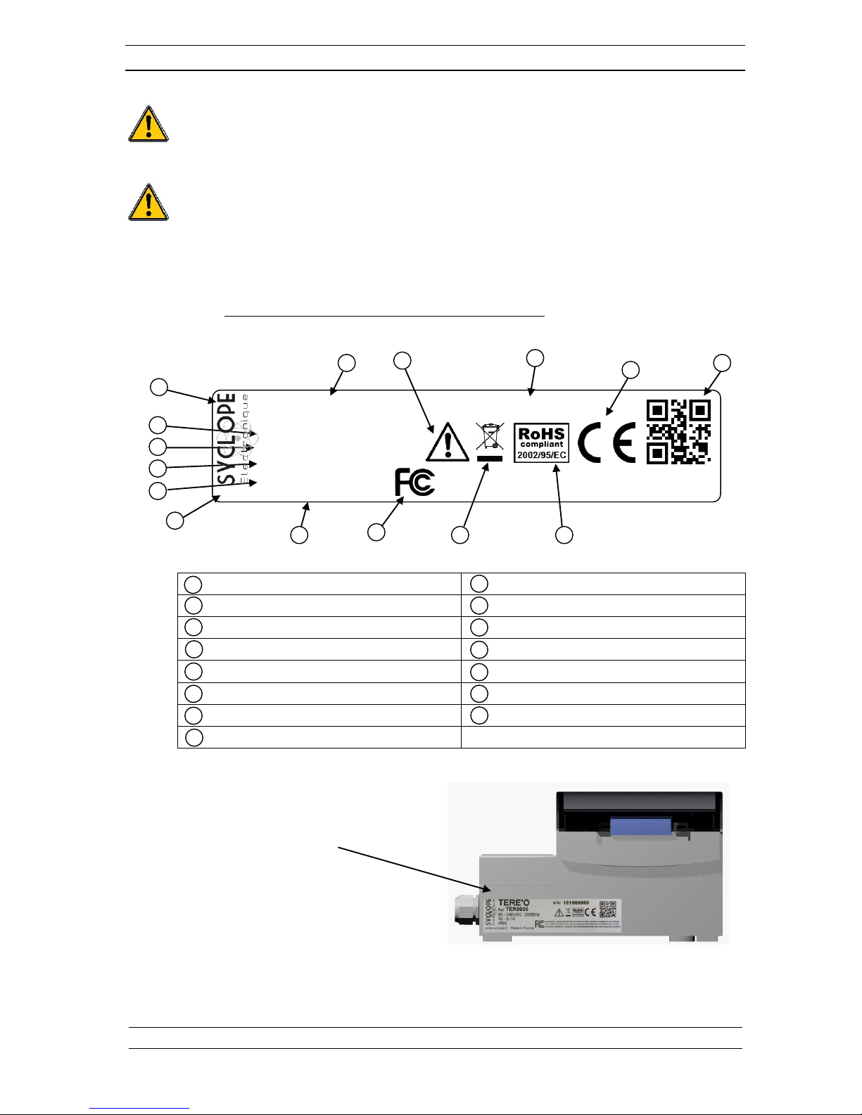
4) Identification and localization of the identification plate ........................................................ 8
5) Disposal and conformity...................................................................................................... 9
III. Fundamental synoptics of communication ...........................................................................10
1) Local connection using maintenance software “TerCom”......................................................10
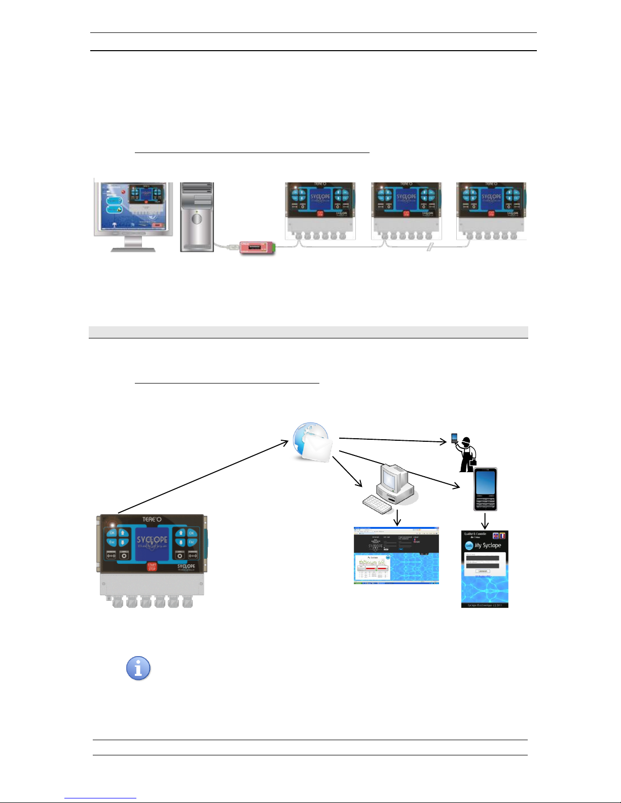
2) Connection to mysyclope.com data website ........................................................................10
IV. Internal modem connections..............................................................................................11
1) Internal connections of GSM, WIFI and Ethernet modems ...................................................11
2) Internal modem connections on electronic plate..................................................................11
V. Data connections...............................................................................................................12
1) RS485 data connection port ...............................................................................................12
2) GSM modem connections...................................................................................................13
3) WIFI Modem connection....................................................................................................13
4) Ethernet Modem connection...............................................................................................14
VI. Programming TERE’O controller .........................................................................................14
1) Communication menu ........................................................................................................14
2) RS485 Communication port................................................................................................15
3) Test GPRS modem ............................................................................................................15
4) Test WIFI modem .............................................................................................................15
5) Test Ethernet modem ........................................................................................................15
VI. Programming software “TerCom” .............................................................................................16
1) Introduction......................................................................................................................16
2) Programming communication port ......................................................................................17
3) Setting ModBus system address .........................................................................................17
4) Test of the connection .......................................................................................................17
5) General Programmation .....................................................................................................18
6) Programming Internet connection ......................................................................................19
7) Maintenance .....................................................................................................................21
VII. Access to the Data web site mysyclope.com........................................................................22
1) Activating your subscription ...............................................................................................22
VIII. ModBus communication registers .......................................................................................24

FCC rules Page 4/28
Communication instructions
The SYCLOPE TERE’O®controller complies with Part 15 of the FCC Rules.
Operation is subject to the following two conditions:
(1) this device may not cause harmful interference (2) this device must accept
any interference received, including interference that may cause undesired
operation FCC Regulations state that unauthorized changes or modifications to
this equipment may void the user’s authority to operate it.
This equipment has been tested and found to comply with the limits for a Class B digital device,
pursuant to Part 15 of the FCC Rules. These limits are designed to provide reasonable protection
against harmful interference in a residential installation. This equipment generates, uses, and can
radiate radio frequency energy and, if not installed and used in accordance with the instructions, may
cause harmful interference to radio communications. However there is no guarantee that interference
will not occur in a particular installation.
If this equipment does cause harmful interference to radio or television reception, which can be
determined by turning the equipment off and on, the user is encouraged to try and correct the
interference by one or more of the following measures:
Reorient or relocate the receiving antenna.
Increase the separation between the equipment and receiver.
Connect this equipment into an outlet on a circuit different from that to which the receiver is
connected.
Consult the dealer or an experienced radio/TV technician for help.
Changes and modifications not expressly approved by the manufacturer could void the user’s
authority to operate this equipment.
Remark :
To ensure compliance with the FCC regulations on electromagnetic interference for a class
B device, use cables properly shielded and connected to the ground as recommended in
this manual. The use of a cable that is not properly shielded or earthed for risk of violating
the FCC rules.

Content Page 5/28
Communications instructions
I. Use of the document
Please read this entire document before starting to install, adjust or commission your device, in
order to ensure the safety of swimmers, users and equipment.
The information provided in this document must be strictly observed. SYCLOPE Electronique France
declines all responsibility in cases where failure to comply with the instructions of this documents is
observed.
The following symbols and pictograms will be used to facilitate reading and understanding of these
instructions.
●Information
►Action to be taken
Item of a list or catalogue
1) Signs and safety symbols
Identify a continuous voltage or a continuous current
Identify an alternative voltage or an alternative current
Protective ground
Functional ground
Risk of injury or accident. Identify a warning concerning a potentially dangerous risk.
Documentation must be consulted by the user with each time the symbol is notified. If the
instructions are not respected, that presents a risk of death, physical injuries or property
damages.
Electric hazard. Identify a warning statement relative to a mortal electric danger. If the
instructions are not strictly respected, that implies an inevitable risk of physical injuries or
death.
Risk of incorrect operation or damage for the device.
Comment or particular information.
Recyclable element

Content Page 6/28
Communications instructions
2) Storage and transport
It is important to store and transport your SYCLOPE TERE’O®in its original packaging in
order to minimize risk of damage.
Furthermore, the package must be stored in an environment that is protected against
humidity and exposure to chemical products.
Environmental conditions for transport and storage:
Temperature : -10 °C to 70 °C
Air humidity: Maximum of 90% with no condensation
3) Packaging
The controller is delivered without electrical power cable.
The pre-holes of the box are drilled and equipped with according electrical glands in compliance
with IP65 level protection. Cables must be adapted to the electrical glands to respect the level
of protection.
Grounded cables for connecting pH and ORP (Redox) sensors are not provided.
Content of the packaging :
One analyzer/controller SYCLOPE TERE’O®
Installation and starting instruction notice
Programming notice
Communication notice (Option)
4) Warranty
The warranty is provided according to the terms of our general conditions of sale and delivery as
long as the following conditions are met:
Use of the equipment according to the instructions of this notice
No modifications of the equipment which may modify its behavior and no incorrect
manipulation
Respect for the electrical safety conditions
Consumable material is no longer covered by the warranty when in use.

Safety and environmental instructions Page 7/28
Communication instructions
II. Safety and environmental instructions
Please:
Read this manual carefully before unpacking, installing or commissioning this equipment
Take into account all the hazards and recommended precautionary measures
Failure to respect these procedures can result in serious injury to users or damage the device.
1) Use of the equipment
The SYCLOPE TERE’O ® system has been designed to measure and regulate pH, Redox (ORP), chlorine
(or bromine) by means of sensors and controls of suitable actuators in the context of the possible uses
described in this manual.
All other uses are considered to be non-conforming and must therefore be forbidden.
SYCLOPE Electronique S.A.S will not be responsible in any case for any damages that result
from such uses.
Any use of sensors or interfaces not-in conformity to the features defined in this handbook
must also be proscribed.
2) User obligations
The user undertakes not to allow its employees to work with the SYCLOPE TERE’O ® equipment
described in this manual unless they:
Are aware of the fundamental instructions relating to work safety and prevention of accidents
Are trained in the use of the device and its environment
Have read and understood these instructions, warnings and manipulation rules
3) Risks prevention
Installation and connection of the SYCLOPE TERE’O®equipment should only be performed by
personnel specialised and qualified for this task.
The installation must comply with current safety standards and instructions!
Before switching the device on or manipulating the relay outputs, remember always to cut off
the primary power supply!
Never open the device when it is powered on!
Maintenance operations and repairs should only be performed by trained, specialised
personnel!
Take care when choosing the location for installing the equipment according to the
environment!
The SYCLOPE TERE’O®electronic box should not be installed in a hazardous environment
and should be protected against splashing with water or chemical products. It should be
installed in a dry, well-ventilated location, isolated from corrosive vapours.

Safety and environmental instructions Page 8/28
Communications instructions
Make sure that the chemical sensors used with this device correspond well to the chemicals
used. Refer to the individual technical note of each sensor. Chemistry of water is very
complex, in case of doubt, contact immediately our engineering service or your approved
installer/reseller.
Chemical sensors are sensitive elements using consumable parts. They must be supervised,
maintained and calibrated regularly using specific calibrator systems not-provided with this
equipment. In the event of defect, a surplus possible hazard of chemical injections can be
noted. In the doubt, a service contract must be taken near your reseller/installer or failing this
near our engineering services. Contact your approved installer/reseller or our business service
for more information.
4) Identification and localization of the identification plate
Label of the manufacturer
Particular risks. Read the notice
Model of the product
Product which can be recycled
Reference of the product
Limitation of dangerous substances
Range of power supply
EC compliance
Values of the maximum current
Country of the manufacturer
Class of protection
Manufacturer square code
Identification of the manufacturer
Conformity with the FCC part 15 Class B
Serial number
Identification plate
1
2
3
4
5
6
7
8
1
2
3
4
5
6
8
11
12
7
14
13
TERE’O
Ref:TER 0000
90 - 240VAC 50/60Hz
www.syclope.fr Made in France
10,2 - 0,16A
IP65
S/N: 151909989
ThisdevicecompileswiththePart.15oftheFCCrules.Operationissubject tothefollowing
two conditions:(1)Thisdevice may notcauseharmful interference,and(2)thisdevice must
acceptanyinterference received,includinginterferencethatmaycauseundesiredoperation
9
10
15
9
10
11
12
13
14
15

Safety and environmental instructions Page 9/28
Communications instructions
5) Disposal and conformity
The recyclable packaging of the SYCLOPE TERE’O®equipment must be disposed of according to
current regulations.
Elements such as paper, cardboard, plastic or any other recyclable elements must be taken to
a suitable sorting center.
According to European directive 2002/96/EC, this symbol means that as of 12 August 2005
electrical appliances cannot be thrown out together with household or industrial waste.
According to current regulations, consumers within the European Union are required, as of
this date, to return their used devices to the manufacturer, who will take care of disposing
them at no extra expense.
According to European directive 2002/95/EC, this symbol means that the SYCLOPE TERE’O®
controller is designed in compliance with the restrictions on hazardous substances
According to low-voltage directive (2006/95/EC) and the electromagnetic compatibility
directive (2004/108/EC), this symbol means that the device has been designed in compliance
with the previously cited directives.
In accordance with part 15 of the FCC regulation (Federal communications commission), this
symbol indicates that the device was tested and approved under the respect and the
conditions of the limits for a Class B digital device.

Paramétrage du TERE’O Page 10/28
Communications instructions
III. Fundamental synoptics of communication
TERE'O controllers was designed to be connected on a RS485 bus using ModBus RTU protocol or with
Internet site “mysyclope.com”. Several controllers can be connected together.
1) Local connection using maintenance software “TerCom”
Connection of one or more TERE'O controllers via RS485 BUS.
In order to connect TERE'O controller to a computer or a PLC, we propose a USB/RS485 interface
module.
Reference
Designation
INF1021
USB/485 interface module
2) Connection to mysyclope.com data website
TERE'O controller can be connected to Internet by GSM/WIFI/IP to mysyclope.com.
Master ModBus Slave ModBus Slave ModBus Slave ModBus
Web site
« Mysyclope.com »
SMS
Brousser
Smartphone

Paramétrage du TERE’O Page 11/28
Communications instructions
In order to connect TERE'O controller to Internet, several internal connection KIT are available.
Reference
Designation
KMD0020
GSM/GPRS MODEM Kit with cable and local antenna
KMD0040
ETHERNET MODEM Kit
KMD0050
WIFI MODEM Kit with cable and local antenna
IV. Internal modem connections
1) Internal connections of GSM, WIFI and Ethernet modems
TERE'O controller can use various types of modem to establish communications with
“mysyclope.com” internet site.
According to the modem type and internet subscription with your provider, data are transmitted to
“mysyclope.com” and thus allow a real-time management of the TERE'O controller. Some messages
can be send to the users by email or SMS and measurements and alarms are recorded.
2) Internal modem connections on electronic plate
The “sockets Modems” are available in option and must be inserted on the electronic plate as shown
below. Corresponding cables are provided with modems.
GSM, WIFI or Ethernet socket Modem place on electronic plate.

Data connections Page 12/28
Communications instructions
V. Data connections
1) RS485 data connection port
Connection into the TERE’O must be done according below:
White : BB’ - B
Blue : AA’ - A
Black : Ground –C
Controllers can be chained with respect of polarity and wired in parallel.
When using the USB/RS485 converter, connection must be done as bellow:
Blue (Terminal block n°3) : AA’ RS485
White (Terminal block n°4) : BB’ RS485
Black (Terminal block n°5) : Ground RS485
Configuration: All switches “ON”
The converter is delivered with an installation CDROM. Use it if necessary!
USB => PC
RS485 controller side

Data connections Page 13/28
Communications instructions
2) GSM modem connections
Install the socket GSM socket modem on good place. Install the antenna into the gland and
connect the cable to the modem. Install the SIM card.
The subscription must be M2M type (Machine to Machine) with minimum capacity of
1Mo/month.
PIN code of SIM card must be deactivated.
Programming connection requires “TerCom” software.
3) WIFI Modem connection
Install the socket WIFI socket modem on good place. Install the antenna into the gland
and connect the cable to the modem.
Programming connection requires “TerCom” software.
GSM Socket MODEM
SIM card
GSM antenna
Antenna cable
WIFI Socket MODEM
WIFI antenna
Antenna cable

Data connections Page 14/28
Communications instructions
4) Ethernet Modem connection
Install the ETHERNET socket modem on good place. Install the link wire into the gland and
connect the cable to the modem as bellow.
Programming connection requires “TerCom” software.
VI. Programming TERE’O controller
1) Communication menu
The general communication menu of the controller allows to program the RS485 communication port
and to display the state of the socket Modem if it is used.
A long push on one of the two keys gives access to the main programming menu…
The keys and allow to navigate in the menu.
The key allows you to confirm your choice
The key allows you to leave the configuration menu
By pressing on OK key whereas the line “Communication” is in
intensified brightness allows to have access to communication RS485
ModBus configuration.
This window also allows to verify the connection statute of the socket
modem when activated.
Configuration
●Language
●Contrast
●Flow switch (E4)
●Calibration Temp.
●Temperature display
●Factory settings
● Communication
Socket MODEM ETHERNET
Ethernet cable
9 : GND
8 : Brown
7 : Brown/White
6 : Blue
5 : Blue/White
4 : Orange
3 : Orange/White
2 : Green
1 : Green/White
EI-A type connection

Programming TERE’O controller Page 15/28
Communications instructions
2) RS485 Communication port
To connect a TERE’O controller on the local BUS, you must configure the data of the RS485
communication port of the controller as well as the others with the same data.
By using and keys allow to select the parameter to be modified,
when the desired parameter is in intensified brightness. Press on OK key
to enter in modification mode.
In modification mode (line blinking) the and keys allow to modify
the value.
To validate, press OK key!
To cancel and to return to the previous menu, press ESC key!
3) Test GPRS modem
If the TERE’O controller uses a GPRS Socket Modem, the “Communication” menu will show
you the statutes of the Modem.
Statutes informations of the SIM card through PIN code.
-READY => SIM Card / Code PIN OK
-SIM PIN => CODE PIN Error
-SIM PUK => CODE PUK Error
Information about GSM signal level.
-Rssi < 16 => Poor Signal
-16 < Rssi < 25 => Average Signal
-Rssi >25 => Good Signal
4) Test WIFI modem
If the TERE’O controller uses a WIFI Socket Modem, the “Communication” menu will show
you the statutes of the Modem.
IP data (With or without DHCP).
-IP : xx.xx.xx.xx => IP system
Information about WIFI signal level.
-Rssi < -100 => Good Signal
--100 < Rssi < -130 => Average Signal
-Rssi <-130 => Poor Signal
5) Test Ethernet modem
If the TERE’O controller uses a GPRS Socket Modem, the “Communication” menu will show
you the statutes of the Modem
IP data (With or without DHCP).
-IP : xx.xx.xx.xx => IP system
●Speed : 9600
●Parity : Even
●Adress : 1
●Protocol : RTU
●Modem : No Modem
●Speed : 9600
●Parity : None
●Adress : 1
●Protocol : RTU
●Modem : Wifi
●IP : 10.10.1.23
●Rssi : -68 dBm
●Speed : 9600
●Parity : None
●Adress : 1
●Protocol : RTU
●Modem : Ethernet
●IP : 10.10.1.23
●Speed : 9600
●Parity : None
●Adress : 1
●Protocol : RTU
●Modem : GPRS
●Pin : READY
●Rssi : 20

Programming software Page 16/28
Communications instructions
VI. Programming software “TerCom”
1) Introduction
The “TerCom” Software allows you to perform maintenance and programming of TERE’O controllers
by using local RS485 communication port. This software is free of charge and it can be downloaded
from our website http://www.syclope.fr
Programming data for the softwa
Accessing keys to specific functions of the software
Communication mode of the software
Information about version of the connected controller.
ModBus system address of the connected controller for communication.
System address
1

Programming software Page 17/28
Communications instructions
2) Programming communication port
Click on « Programming » button
Local Port (Connecting by RS485 bus):
- Select the Com Port used by the computer
- Select the speed (Must be identical to the
connected controller on the data bus)
-
Select the parity (Must be identical to the
connected controller on the data bus)
Validate your configuration by pressing “Save”!
If the RS485 converter doesn’t appear into the list of Port Com connected, click on the
“Actualise” button to refresh the list.
3) Setting ModBus system address
System address (ModBus Address):
- Before testing the communication, you must indicate
the address of the controller (ModBus address)
4) Test of the connection
Click on the information button to display ID, name and version of the controller.

Programming software Page 18/28
Communications instructions
5) General Programmation
Click of the Programming button
Allows to upload the configuration from the connected controller.
Allows to program the connected controller with the present parameters.
Allows to load a configuration file already recorded.
Allows to save the present configuration file into the laptop.
Calibration of the sensors is not possible with the software.
Calibration parameters are saved and downloaded with the same values.
Please, refer to the standard programming Manuel for commissioning the controller.

Programming software Page 19/28
Communications instructions
6) Programming Internet connection
Internet programming connection with the keypad of the controller is not available. You must
connect the TERE’O controller to the RS485 port by using TerCom software to perform the
programming.
The TERE’O controller will be identified on the data website by his serial number!
The other parameters to be programmed are the website address and the port number. By
default, these parameters are written in the memory and must not be changed except a
request of the technical service of SYCLOPE Electronique.
Mode of internet remote connection must be selected with corresponding data in the
windows.
Selecting GPRS mode:
-Select GPRS Modem
-Enter the APN of your SIM Card.
The APN (Access Point Name) of the SIM Card is given by your provider.
Don’t forget to ask it to your provider for programming the connection.
Selecting ETHERNET mode:
-Select ETHERNET modem
-If the Network use a DHCP …
Select:
“Get an IP address automatically”
-If the network use a static IP …
Select:
“Use the following IP address”
… and enter:
-IP Address
-Subnet Mask
-Default Gateway
-Enter DNS of the network or from the
provider to access internet.
12-49-01234

Programming software Page 20/28
Communications instructions
Selecting WIFI mode:
-Select WIFI Modem
-If the Network use a DHCP …
Select:
“Get an IP address automatically”
-If the network use a static IP …
Select:
“Use the following IP address”
… and enter:
-IP Address
-Subnet Mask
-Default Gateway
-Enter DNS of the network or from the
provider to access internet.
-Enter all parameters concerning active WIFI
connection…
… and enter:
-SSID : Name of the port
-Speed : Speed of communication
-Channel : WIFI Channel selected
-Country : Rules of the country
-Mode : Network type
-Security : Encryption
-Key : Password or network code
Other manuals for TERE'O
1
Table of contents
Other SYCLOPE Lighting Equipment manuals