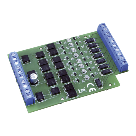
tams elektronik GBM-8 User manual

Manual
GBM-8
Item no. 52-01085 | 52-01086 | 52-01087
8-fold Track Busy Ind cator
tams elektron k
n n n

Engl sh GBM-8
Table of contents
1. Gett ng started............................................................................3
2. Safety nstruct ons.......................................................................5
3. Safe and correct solder ng...........................................................7
4. Operat on overv ew.....................................................................9
5. Techn cal spec f cat ons..............................................................11
6. Assembl ng the k t.....................................................................12
7. Perform ng a funct onal check....................................................18
8. Connect ng the GBM-8...............................................................20
9. Check l st for troubleshoot ng.....................................................25
10. Guarantee bond........................................................................26
11. EU declarat on of conform ty......................................................27
12. Declarat ons conform ng to the WEEE d rect ve...........................27
© 10/2015 Tams Elektron k GmbH
All r ghts reserved. No part of th s publ cat on may be reproduced or
transm tted n any form or by any means, electron c or mechan cal,
nclud ng photocopy ng, w thout pr or perm ss on n wr t ng from Tams
Elektron k GmbH.
Subject to techn cal mod f cat on.
The asterisks **
** Products out of the programme of the Tams Elektron k GmbH
Page 2

!
GBM-8 Engl sh
1. Gett ng started
How to use this manual
Th s manual g ves step-by-step nstruct ons for safe and correct
assembly of the k t and f tt ng and connect ng of the ready-bu lt
module, and operat on. Before you start, we adv se you to read the
whole manual, part cularly the chapter on safety nstruct ons and the
checkl st for trouble shoot ng. You w ll then know where to take care
and how to prevent m stakes wh ch take a lot of effort to correct.
Keep th s manual safely so that you can solve problems n the future. If
you pass the k t or the ready-bu lt module on to another person, please
pass on the manual w th t.
Intended use
The track busy nd cator GBM-8 s des gned to be operated accord ng to
the nstruct ons n th s manual n model bu ld ng, espec ally w th model
ra lways. Any other use s nappropr ate and nval dates any guarantees.
The GBM-8 should not be assembled or mounted by ch ldren under the
age of 14.
Read ng, understand ng and follow ng the nstruct ons n th s manual
are mandatory for the user.
Caution:
The track busy nd cator GBM-8 conta ns ntegrated c rcu ts. These are
very sens t ve to stat c electr c ty. Do not touch components w thout
f rst d scharg ng yourself. Touch ng a rad ator or other grounded metal
part w ll d scharge you.
Page 3

Engl sh GBM-8
Checking the package contents
Please make sure that your package conta ns:
one k t, conta n ng the components l sted n the parts l st (à page
14) and one PCB or
one ready-bu lt module or
one ready-bu lt module n a hous ng (complete un t);
components for the aux l ary c rcu t for the funct onal test:
2 res stors 1 kW, 1 d ode 1N4148, 1 LED;
a CD (conta n ng the manual and further nformat on).
Required materials
For assembl ng the k t you need:
an electron c solder ng ron (max. 30 Watt) or a regulated solder ng
ron w th a f ne t p and a solder ng ron stand,
a t p-clean ng sponge,
a heat-res stant mat,
a small s de cutter and w re str pper,
as necessary a pa r of tweezers and long nose pl ers,
electron c t n solder (0,5 mm. d ameter).
For test ng the module you need an electr c l ght bulb.
In order to connect the module you need w re. Recommended
d ameters: > 0,25 mm² for all connect ons (e.g. tem no. 73-1031x,
x=0..9).
If you want to d splay the busy status you need LEDs and su table
ser es res stors.
Page 4

GBM-8 Engl sh
2. Safety nstruct ons
Mechanical hazards
Cut w res can have sharp ends and can cause ser ous njur es. Watch
out for sharp edges when you p ck up the PCB.
V s bly damaged parts can cause unpred ctable danger. Do not use
damaged parts: recycle and replace them w th new ones.
Electrical hazards
Touch ng powered, l ve components,
touch ng conduct ng components wh ch are l ve due to malfunct on,
short c rcu ts and connect ng the c rcu t to another voltage than
spec f ed,
mperm ss bly h gh hum d ty and condensat on bu ld up
can cause ser ous njury due to electr cal shock. Take the follow ng
precaut ons to prevent th s danger:
Never perform w r ng on a powered module.
Assembl ng and mount ng the k t should only be done n closed,
clean, dry rooms. Beware of hum d ty.
Only use low power for th s module as descr bed n th s manual and
only use cert f ed transformers.
Connect transformers and solder ng rons only n approved ma ns
sockets nstalled by an author sed electr c an.
Observe cable d ameter requ rements.
After condensat on bu ld up, allow a m n mum of 2 hours for
d spers on.
Use only or g nal spare parts f you have to repa r the k t or the
ready-bu lt module.
Page 5

!
Engl sh GBM-8
ire risk
Touch ng flammable mater al w th a hot solder ng ron can cause f re,
wh ch can result n njury or death through burns or suffocat on.
Connect your solder ng ron or solder ng stat on only when actually
needed. Always keep the solder ng ron away from nflammable
mater als. Use a su table solder ng ron stand. Never leave a hot
solder ng ron or stat on unattended.
Thermal danger
A hot solder ng ron or l qu d solder acc dentally touch ng your sk n can
cause sk n burns. As a precaut on:
use a heat-res stant mat dur ng solder ng,
always put the hot solder ng ron n the solder ng ron stand,
po nt the solder ng ron t p carefully when solder ng, and
remove l qu d solder w th a th ck wet rag or wet sponge from the
solder ng t p.
Dangerous environments
A work ng area that s too small or cramped s unsu table and can cause
acc dents, f res and njury. Prevent th s by work ng n a clean, dry room
w th enough freedom of movement.
Other dangers
Ch ldren can cause any of the acc dents ment oned above because they
are nattent ve and not respons ble enough. Ch ldren under the age of
14 should not be allowed to work w th th s k t or the ready-bu lt
module.
Caution:
L ttle ch ldren can swallow small components w th sharp edges, w th
fatal results! Do not allow components to reach small ch ldren.
Page 6

!
GBM-8 Engl sh
In schools, tra n ng centres, clubs and workshops, assembly must be
superv sed by qual f ed personnel.
In ndustr al nst tut ons, health and safety regulat ons apply ng to
electron c work must be adhered to.
3. Safe and correct solder ng
Caution:
Incorrect solder ng can cause dangers through f res and heat. Avo d
these dangers by read ng and follow ng the d rect ons g ven n the
chapter Safety instructions.
Use a small solder ng ron w th max. 30 Watt or a regulated
solder ng ron.
Only use electron c t n solder w th flux.
When solder ng electron c c rcu ts never use solder ng-water or
solder ng grease. They conta n ac ds that can corrode components
and copper tracks.
Insert the component connect ng p ns nto the PCB´s holes as far as
poss ble w thout force. The components should be close to the
PCB`s surface.
Observe correct polar ty or entat on of the parts before solder ng.
Solder qu ckly: hold ng the ron on the jo nts longer than necessary
can destroy components and can damage copper tracks or solder ng
eyes.
Apply the solder ng t p to the solder ng spot n such a way that the
part and the solder ng eye are heated at the same t me.
S multaneously add solder (not too much). As soon as the solder
becomes l qu d take t away. Hold the solder ng t p at the spot for a
few seconds so that the solder flows nto the jo nt, then remove the
solder ng ron.
Page 7

Engl sh GBM-8
Do not move the component for about 5 seconds after solder ng.
To make a good solder ng jo nt you must use a clean and unox d sed
solder ng t p. Clean the solder ng t p w th a damp p ece of cloth, a
damp sponge or a p ece of s l con cloth.
Cut the w res after solder ng d rectly above the solder ng jo nt w th a
s de cutter.
After plac ng the parts, please double check for correct polar ty.
Check the PCB tracks for solder br dges and short c rcu ts created by
acc dent. Th s would cause faulty operat on or, n the worst case,
damage. You can remove excess solder by putt ng a clean solder ng
t p on the spot. The solder w ll become l qu d aga n and flow from
the solder ng spot to the solder ng t p.
Page 8

GBM-8 Engl sh
4. Operat on overv ew
The track busy nd cator GBM-8 can superv se a max mum of e ght
ndependent track sect ons. The GBM-8 s nternally d v ded nto four
sect ons w th two track busy nd cators each, wh ch can be connected to
a max mum of four d fferent booster or transformer sect ons.
Application
The track busy nd cator GBM-8 s su table for use n model ra lway
layouts of all gauges:
n analogue (d.c. or a.c.) layouts, e.g. as a part of a block s gnal
control or an automated control or
n d g tal layouts (w th all d g tal formats), e.g. n comb nat on w th
feedback modules read ng n mass contacts (e.g. s88).
The GBM-8 has been opt m sed for use n d g tal layouts of gauges
start ng from TT:
False reports occur ng n d g tal operat on due to nterferences, are
m n m zed on account of the comparat vely low sens t v ty of 6 mA.
The n- and outputs of the GBM-8 are galvan cally solated from each
other.
The e ght outputs of the GBM-8 are arranged so as to be connected
d rectly to the nputs of the s88-feedback modules S88-3** oder
S88-4**.
Voltage supply
The GBM-8 s suppl ed d rectly v a the ra ls.
Detection of vehicles
The GBM-8 detects veh cles consum ng at least 6 mA (e.g. locomot ves
and carr ages w th l ght ng) located n the connected sect on.
H nt: As a rule, the small current flow ng after pa nt ng a carr age´s
axle w th res st ve lacquer s not h gh enough to be detected by the
Page 9

Engl sh GBM-8
GBM-8. For th s appl cat on the fourfold track busy nd cator GBM-1**
can be used.
Due to techn cal pr nc ples, w th (analogue) d.c. layouts the GBM-8 can
only detect veh cles dr v ng nto the superv sed track sect ons n a
part cular d rect on. In case the detect on of veh cles from both
d rect ons s requ red, the track busy nd cator GBM-1** can be used.
Electr c consumers located n a sw tched off track sect on can be
detected by the GBM-1 when
an add t onal res stor s mounted n parallel to the sw tch between
the sw tched off sect on and the assoc ated nput of the module and
at the same t me the supply voltage s appl ed to the not superv sed
ra l sect ons.
Evaluation of the busy messages and transmission to digital
feedback modules
As soon as the GBM-8 detects an electr c current consumer n a
connected track sect on, the l nked output s nternally connected to the
output M. Th s way, the output of the GBM-8 works l ke a sw tch
sw tch ng to earth.
D g tal feedback modules (e.g. s88-feedback modules) can be
connected d rectly to the outputs. The e ght outputs of the GBM-8 are
arranged so as to be connected d rectly to the nputs of the s88-
feedback modules S88-3** oder S88-4**.
The n- and outputs of the GBM-8 are solated from each other by opto-
couplers. Consequently nterferences are f ltered out and hum loops
and fault currents are prevented effect vely.
Displaying the busy messages
Espec ally n analogue d splays, you can d splay the busy messages w th
LEDs (together w th su table ser es res stors) connected to the outputs.
Page 10

GBM-8 Engl sh
Outputs
The outputs of the GBM-8 are su table for a load of max mum 50 mA
each. For that reason they are not su table for the connect on of electr c
l ght bulbs, relays or subord nate c rcu ts w th a current consumpt on of
more than 50 mA. For these appl cat ons the fourfold track busy
nd cator GBM-1** can be used.
5. Techn cal spec f cat ons
Voltage supply v a the ra ls
Current consumpt on (w thout
connected dev ces) approx. 15 mA
Number of mon tored sect ons 8
Max mum current
n the mon tored sect ons 3.000 mA
Sens v ty 6 mA
Number of outputs 8
Max. current per output 50 mA
Protected to IP 00
Amb ent temperature n use 0 ... +60 °C
Amb ent temperature n storage -10 ... +80 °C
Comparat ve hum d ty allowed max. 85 %
D mens ons of the PCB
D mens ons nclud ng hous ng
approx. 72 x 95 mm
approx. 100 x 98 x 35 mm
We ght of the assembled board
We ght nclud ng hous ng
approx. 70 g
approx. 110 g
Page 11

Engl sh GBM-8
6. Assembl ng the k t
You can sk p th s part f you have purchased a ready-bu lt module or dev ce.
Preparation
Put the sorted components n front of you on your workbench.
The separate electron c components have the follow ng spec al features
you should take nto account n assembl ng:
Resistors
Res stors reduce current.
The value of res stors for smaller power rat ngs s nd cated
through colour r ngs. Every colour stands for another
f gure.
Carbon f lm res stors have 4 colour r ngs. The 4th r ng
(g ven n brackets here) nd cates the tolerance of the
res stor (gold = 5 %).
Value: Colour r ngs:
1 kbrown - black - red (gold)
4,7 kyellow - v olet - red (gold)
Diodes and Zener diodes
D odes allow the current to pass through n one d rect on
only (forward d rect on), s multaneously the voltage s
reduced by 0,3 to 0,8 V. Exceed ng of the l m t voltage
always w ll destroy the d ode, and allow current to flow n
the reverse d rect on.
The d ode type s pr nted on the package.
Page 12

GBM-8 Engl sh
Transistors
Trans stors are current ampl f ers wh ch convert low s gnals nto
stronger ones. There are several types n d fferent package forms
ava lable. The type des gnat on s pr nted on the component.
Trans stors for a low power rat ng (e.g. BC types) have a
package n form of a half zyl nder (SOT-package).
The three p ns of b polar trans stors (e.g. BC, BD and BT
types) are called bas s, em tter and collector (abbrev ated
w th the letters B, E, C n the c rcu t d agram).
Integrated circuits (ICs)
Depend ng on the type, ICs fulf l var ous tasks. The most
common hous ng form s the so-called "DIL"-hous ng, from
wh ch 4, 6, 8, 14, 16, 18 or more "legs" (p ns) are
arranged along the long s des.
ICs are sens t ve to damage dur ng solder ng (heat,
electrostat c charg ng). For that reason n the place of the
ICs IC sockets are soldered n, n wh ch the ICs are
nserted later.
Opto couplers
Opto couplers are ICs, wh ch work s m lar to laser beam sw tches. They
comb ne n one hous ng a l ght em tt ng d ode and a photo trans stor. The r
task s the transm ss on of nformat on w thout galvan c connect on. They
are n a DIL-hous ng w th at least 4 p ns.
Terminal strips
Term nal str ps are solder- n screw-type term nals. They prov de a
solder-free and safe connect on of the cables to the c rcu t, wh ch can
st ll be separated any t me.
Page 13

English GBM-8
Parts list
Carbon film
resistors
R9, R10, R11, R12, R13, R14,
R15, R1
1 kW
R1, R2, R3, R4, R5, R , R7, R8 4,7 kW
Diodes D1 - D1 1N540x, x > 2
Transistors T1, T2, T3, T4, T5, T , T7, T8 BC547B
Photocoupleurs OK1, OK2, OK3, OK4 827
or 2 x 817
IC-sockets OK1, OK2, OK3, OK4 8-pole
Terminal strips X1 - X3 3 x 3-pole
Double terminal
strips
X4 2 x 3-pole
1 x 2-pole
Page 14

GBM-8 English
PCB layout
Page 15

!
English GBM-8
Assembly
Proceed according to the order given in the list below. First solder the
components on the solder side of the PCB and then cut the excess
wires with the side cutter. Follow the instructions on soldering in
section 3.
Caution:
Several components have to be mounted according to their polarity.
When soldering these components the wrong way round, they can be
damaged when you connect the power. In the worst case the whole
circuit can be damaged. At the best, a wrongly connected part will not
function.
1. Resistors Mounting orientation of no importance.
2. Wire bridges Br1
to Br4
Use the off-cut wires of the resistors.
3. IC sockets Mount the sockets that way, the markings on
the sockets show in the same direction as the
markings on the PCB board.
4. Transistors Observe the polarity!
The cross section of transistors for a low
power rating in SOT-packages is shown in the
PCB layout.
5. Diodes Observe the polarity!
The negative end of the diodes is marked with
a ring. This is shown in the PCB layout. Solder
the diodes that way,their bodies are standing
upright on the PCB.
. Terminal strips Put together the terminal strips before
mounting them.
Page 1

GBM-8 English
7. Photocoupleurs
in DIL-housing
Insert the ICs into the soldered socket.
Do not touch the ICs without first discharging
yourself by touching a radiator or other
grounded metal parts.
Do not bend the "legs" when inserting them
into the sockets. Check that the markings on
the PCB, the socket and the IC show to the
same direction.
or
Performing a visual check
Perform a visual check after the assembly of the module and remove
faults if necessary:
Remove all loose parts, wire ends or drops of solder from the PCB.
Remove all sharp wire ends.
Check that solder contacts which are close to each other are not
unintentionally connected to each other. Risk of short circuit!
Check that all components are polarised correctly.
When you have remedied all faults, go on to the next part.
Page 17

Engl sh GBM-8
7. Perform ng a funct onal check
It s recommended to perform a funct onal test before nstall ng the
GBM-8 nto the layout. Test the module w th a small aux l ary c rcu t.
The requ red components are ncluded n the package.
Follow the connect ons d agram "Test ng layout" and the l st
"Ass gnment of the booster sect ons or transformers and the ra l
sect ons to the GBM-8" n sect on 8. There are term nal str ps soldered
to the module wh ch are used to nsert and screw on the connect ng
cables.
Test for rail section 1
GBM-8 Connect on to
V1a, V1b and M Transformer
A1 Aux l ary c rcu t made of:
LED, ser es res stor 1 kW and damp ng d ode.
Observe the polar ty of the LED and the damp ng
d ode! W th w red LEDs the longer lead s always
the anode (pos t ve pole). The negat ve end of the
damp ng d ode s marked w th a r ng.
G1 and V1a Res stor 1 kW → s mulat on of a load n the
superv sed ra l sect on 1
After connect ng the transformer w th the power supply, the LED
should l ght. D sconnect the connect on between G1 and the res stor,
the LED should go out.
Repeat the test for all other track sect ons. Be sure to connect the
connect ons for the power supply, the ra ls and the output, wh ch are
ass gned to each other (e.g. V3a, V3b, G5 and A5).
Page 18

!
GBM-8 Engl sh
Testing layout
Caution: Never connect electr c l ght bulbs to the outputs as
these consume more than 50 mA current, as a rule. The outputs wh ch
are des gned for a max mum current of 50 mA would be destroyed
when putt ng them nto operat on.
Page 19

!
Engl sh GBM-8
If the funct onal test s not successful for one or several outputs, check
f the opto-couplers and the d odes have been mounted polar zed
correctly. Follow the h nts n sect on 9, as well.
Caution: When a component gets too hot, d sconnect the
module mmed ately from the power supply. R sk of short c rcu t!
Check the assembly.
After perform ng a successful funct on test, d sconnect the track busy
nd cator from the voltage supply and cont nue w th the connect on of
the module.
8. Connect ng the GBM-8
There are term nal str ps soldered to the module wh ch are used to
nsert and screw on the connect ng cables.
Assignment of the booster sections or transformers and the rail
sections to the GBM-8
Booster
sect on or
transformer
Ra l sect on GBM-8
Supply voltage Ra l Output
11V1a and V1b G1 A1
2 G2 A2
23V2a and V2b G3 A3
4 G4 A4
35V3a and V3b G5 A5
6 G6 A6
47V4a and V4b G7 A7
8 G8 A8
Page 20
This manual suits for next models
3
Table of contents
Other tams elektronik Measuring Instrument manuals