tams elektronik 70-01045 User manual

Adapter for PluX22-
and 21MTC-Interface
Manual
Item number 70-01045
PluX22
NEM 58 | RCN-122
NEM 0 | RCN-121
tams elektronik
n n n

Adapter for PluX22- and 21MTC-Interface tams elektronik
Contents
1. Getting started.............................................................................................................3
1.1. Contents of the package.......................................................................................3
1.2. Accessories..........................................................................................................3
1.3. Intended use.......................................................................................................3
2. Operation overview.......................................................................................................4
2.1. Background information........................................................................................4
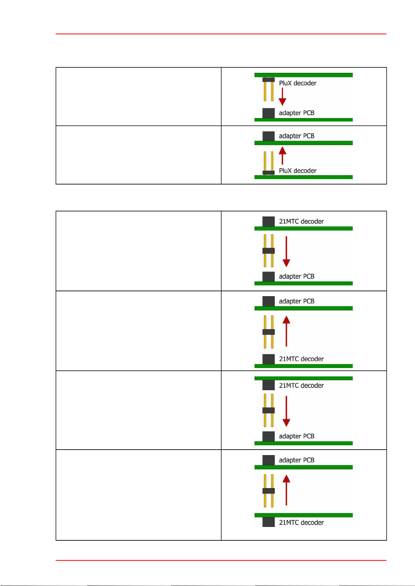
2.2. Mounting versions................................................................................................4
2.3. Mounting versions for PluX decoders.....................................................................5
2.4. Mounting versions for MTC decoders.....................................................................5
3. Assembling the kit........................................................................................................
3.1. Safety instructions................................................................................................
3.2. Safe and correct soldering....................................................................................7
3.3. Soldering on the cables.........................................................................................8
3.4. Assignment for PluX adapters (NEM 58/RCN-122).................................................8
3.5. Assignment for 21MTC adapters (NEM 0/RCN-121)...........................................10
4. Checklist for troubleshooting and error correction.........................................................12
4.1. Technical Hotline................................................................................................12
4.2. Repairs..............................................................................................................12
5. Technical data............................................................................................................13
. Warranty, EU conformity & WEEE................................................................................14
.1. Guarantee bond.................................................................................................14
.2. EU Declaration of Conformity..............................................................................15
.3. Declarations on the WEEE Directive.....................................................................15
Version 2.0 | Status: 10/2023
© Tams Elektronik GmbH
All rights reserved, in particular the right of reproduction, distribution and translation. Copies,
reproductions and alterations in any form require the written permission of Tams Elektronik
GmbH. We reserve the right to make technical changes.
Printing t e manual
The formatting is optimised for double-sided printing. The standard page size is DIN A5. If
you prefer a larger display, printing on DIN A4 is recommended.
2 | Contents

tams elektronik Adapter for PluX22- and 21MTC-Interface
1. Getting started
This manual gives step-by-step instructions for safe and correct assembly of the kit and fitting
and connecting of the adapter, and operation. Before you start, we advise you to read the
whole manual, particularly the chapter on safety instructions and the checklist for trouble
shooting. You will then know where to take care and how to prevent mistakes which take a lot
of effort to correct.
Keep this manual safely so that you can solve problems in the future. If you pass the kit or the
ready-built adapter on to another person, please pass on the manual with it.
1.1. Contents of the package
one adapter PCB
one 22-pole plug connector for use as MTC-interface
1.2. Accessories
To assemble t e kit you will need
a soldering iron with temperature control and a thin tip and a deposit stand or a controlled
soldering station
a scraper, rag or sponge
a heat-resistant pad
a small pair of side cutters and wire strippers
tweezers and flat-nose pliers if necessary
electronic solder (preferably 0.5 to 0.8 mm diameter)
Connection cables
The use of stranded wire is recommended for making the connections. Stranded wires consist
of several thin individual wires and are therefore more flexible than rigid wires with the same
copper cross-section. Recommended cross-sections:
0.04 to 0.10 mm² (depending on the load)
1.3. Intended use
The adapter is intended for use in model construction, especially in model railway layouts,
according to the specifications in the manual. Any other use is not in accordance with the
intended use and will result in the loss of the warranty claim. Intended use also includes
reading, understanding and following all parts of the instructions. The adapter is not intended
to be used by children under the age of 14.
Getting started | 3

Adapter for PluX22- and 21MTC-Interface tams elektronik
2. Operation overview
The adapter is used to upgrade vehicles with a PluX or MTC interface interface. There is a 22-
pole socket soldered on to the adapter PCB which is used to insert the plug connector of the
decoder-sided PluX interface. In order to connect the adapter to the the decoder-sided MTC
interface, the extra 22-pole plug connector has to be inserted into the adapter PCB.
2.1. Background information
PluX interfaces MTC interfaces
Standard NEM 58 / RCN-122 NEM 0 / RCN-121
Number of pins 12, 1 or 22 22
Plug connector on the decoder in the vehicle
Socket in the vehicle on the decoder
PluX interfaces for different gauges
PluX-interfaces have 12, 1 or 22 connector pins and that way are suitable to be mounted in
vehicles of different gauges (or with varying space requirements). The assignment of the
different versions allows to insert a plug connector with 12 or 1 connector pins into a socket
with a larger number of connections.
Index-pin
For both types of interfaces the position of an index-pin which should not be used has been
defined. By means of the index-pin you can distinguish the direction for inserting the plug
connector into the socket. At the position of the plug connector in question the pin should be
removed.
2.2. Mounting versions
The (PluX- or MTC-) vehicle decoder can be inserted as well from the top as from the bottom
into the adapter PCB. The assignment of the PCB´s contacts depends on the direction of
inserting the decoder.
4 | Operation overview

tams elektronik Adapter for PluX22- and 21MTC-Interface
2.3. Mounting versions for PluX decoders
Mounting version 1:
Inserting direction of the decoder:
from above
Mounting version 2:
Inserting direction of the decoder:
from below
2.4. Mounting versions for MTC decoders
Mounting version 1 a:
Inserting direction of the decoder:
from above
+
Socket terminal strip of the decoder on top
Mounting version 1 b:
Inserting direction of the decoder:
from below
+
Socket terminal strip of the decoder on top
Mounting version 2 a:
Inserting direction of the decoder:
from above
+
Socket terminal strip of the decoder at the
bottom
Mounting version 2 b:
Inserting direction of the decoder:
from below
+
Socket terminal strip of the decoder at the
bottom
Operation overview | 5

!
Adapter for PluX22- and 21MTC-Interface tams elektronik
3. Assembling the kit
3.1. Safety instructions
Mec anical azards
Cut wires can have sharp ends and can cause serious injuries. Watch out for sharp edges
when you pick up the PCB.
Visibly damaged parts can cause unpredictable danger. Do not use damaged parts: recycle
and replace them with new ones.
Fire risk
Touching flammable material with a hot soldering iron can cause fire, which can result in
injury or death through burns or suffocation. Connect your soldering iron or soldering station
only when actually needed. Always keep the soldering iron away from inflammable materials.
Use a suitable soldering iron stand. Never leave a hot soldering iron or station unattended.
T ermal danger
A hot soldering iron or liquid solder accidentally touching your skin can cause skin burns. As a
precaution:
use a heat-resistant mat during soldering,
always put the hot soldering iron in the soldering iron stand,
point the soldering iron tip carefully when soldering, and
remove liquid solder with a thick wet rag or wet sponge from the soldering tip.
Dangerous environments
A working area that is too small or cramped is unsuitable and can cause accidents, fires and
injury. Prevent this by working in a clean, dry room with enough freedom of movement.
Ot er dangers
Children can cause any of the accidents mentioned above because they are inattentive and
not responsible enough. Children under the age of 14 should not be allowed to work with this
kit or the ready-built device.
Caution:
Little children can swallow small components with sharp edges, with fatal results! Do not
allow components to reach small children.
In schools, training centres, clubs and workshops, assembly must be supervised by qualified
personnel. In industrial institutions, health and safety regulations applying to electronic work
must be adhered to.
| Assembling the kit

!
tams elektronik Adapter for PluX22- and 21MTC-Interface
3.2. Safe and correct soldering
Caution:
Incorrect soldering can cause dangers through fires and heat. Avoid these dangers by
reading and following the directions given in the chapter Safety instructions.
Use a soldering iron with temperature control, which you set to approx. 300 °C.
Only use electronic solder with a flux.
Never use soldering fluid or soldering grease when soldering electronic circuits. These
contain an acid that destroys components and conductor paths.
Solder quickly: Soldering for too long can detach solder pads or tracks or even destroy
components.
Hold the soldering tip on the soldering point so that it touches the wire and the pad at the
same time. Add (not too much) solder simultaneously. As soon as the solder begins to flow,
remove it from the soldering point. Then wait a moment for the solder to flow well before
removing the soldering iron from the soldering joint.
Do not move the created solder joint for about 5 seconds.
A clean, non-oxidized soldering tip is essential for a perfect soldering joint and good
soldering. Therefore, before each soldering, wipe off excess solder and dirt with a damp
sponge, a thick damp cloth or a silicone wiper.
After soldering, check (preferably with a magnifying glass) whether connections or tracks
have been bridged with solder by mistake. This can lead to malfunction or destruction of
components or, in the worst case, the complete circuit. You can re-liquefy excess solder
with the clean hot soldering tip. The solder then flows from the board onto the soldering
tip.
Assembling the kit | 7

!
Adapter for PluX22- and 21MTC-Interface tams elektronik
3.3. Soldering on the cables
Solder the connecting cables on the top side of the adapter PCB. Observe the different
assignments for PluX and MTC interfaces and the different mounting versions.
It is recommended to use cables of different colours according to NEM 58 or NEM 0 in
order to avoid mistakes when connecting the adapter PCB.
Perform a visual c eck!
After having soldered the cables you should perform a visual check and remedy defects.
Check if soldering joints closely adjoining are connected to each other by accident. Risk of
short circuit!
Check if you have assigned the connecting cables on the adapter PCB properly to the
connections of the decoder.
Caution:
Confusing the connections can cause damages at the deocder and/or at the vehicle. For that
reason you should be very attentive when assigning the connections.
3.4. Assignment for PluX adapters (NEM 58/RCN-122)
PluX adapter
Mounting version 1
Inserting direction of t e decoder:
from above
Mounting version 2
Inserting direction of t e decoder:
from below
Figure: Top side of the adapter PCB
Assignment for use according to PluX (NEM 58 / RCN-122)
11 = Index-Pin
8 | Assembling the kit

tams elektronik Adapter for PluX22- and 21MTC-Interface
PluX adapter
Pin Name Description Plux adapter Cable
colour
1 GPIO/C Universal input/output
2 AUX3 Output 3
3 GPIO/B Universal input/output, train-bus pulse
4 GPIO/A Universal input/output, train-bus data
5 GND Decoder ground, pick-off after rectifier
V+ Cap. Decoder plus, pick-off after rectifier,
connection storage capacitor
blue
7 F0f Lighting forward direction white
8 Motor 1 Motor connection 1 (+) / forwards orange
9 V+ Decoder plus, pick-off after rectifier blue
10 Motor 2 Motor connection 2 (-) / backwards grey
11 Index not in use, coding
12 Rails 1 Current collector right in forward direction of
motion
red
13 F0r Lighting backward direction yellow
14 Rails 2 Current collector left in forward direction of
motion
black
15 LS/A Loudspeaker connection A
1 AUX1 Output 1 green
17 LS/B Loudspeaker connection B
18 AUX2 Output 2 violet
19 AUX4 Output 4
20 AUX5 Output 5
21 AUX Output
22 AUX7 Output 7
Assembling the kit | 9

Adapter for PluX22- and 21MTC-Interface tams elektronik
3.5. Assignment for 21MTC adapters (NEM 0/RCN-121)
In order to avoid damage due to a connection of the decoder with reversed polarity, you sould
remove the index pin (pin 11) at the 22-pole plug connector. You can withdraw the pin with
small pliers.
MTC adapter
Mounting version 1 (a and b)
Socket terminal strip of t e decoder
on top
Mounting version 2 (a and b)
Socket terminal strip of t e decoder
at t e bottom
1a 2a
1b 2b
Figure: Top side of the adapter PCB
Assignment for use according to 21MTC (NEM 0 / RCN-121)
11 = Index-Pin
10 | Assembling the kit

tams elektronik Adapter for PluX22- and 21MTC-Interface
MTC adapter
Pin Name Description MTC adapter Cable
colour
1 Input1 Sensor input 1
2 Input2 Sensor input 2
3 AUX Output
4 AUX4 Output 4
5 ZBCLK Pulse generator train bus
ZBDTA Data train bus (TxD, RxD)
7 F0r Lighting forward direction yellow
8 F0f Lighting backward direction white
9 LS/A Loudspeaker connection A brown
10 LS/B Loudspeaker connection B brown
11 Index not in use, coding
12 Vcc Internal decoder voltage 1,8 – 5,7 volts
13 AUX3 Output 3
14 AUX2 Output 2 violet
15 AUX1 Output 1 green
1 V+ Decoder plus, pick-off after rectifier,
connection storage capacitor
blue
17 AUX5 Output 5
18 Motor2 Motor connection 2 minus / backwards grey
19 Motor1 Motor connection 1 plus / forwards orange
20 GND Decoder ground, pick-off after rectifier
21 Rails left Rails left in forward direction of motion black
22 Rails right Rails right in forward direction of motion red
Assembling the kit | 11

!
Adapter for PluX22- and 21MTC-Interface tams elektronik
4. Checklist for troubleshooting and error correction
Warning:
If you notice a strong heat development, immediately disconnect the connection to the
supply voltage. Fire azard!
Possible causes:
The connecting cables on the PCB are badly assigned to the connections of the decoder or
the vehicle. à Perform a visual check and remedy defects. Damage on the decoder or the
vehicle cannot be excluded.
The plug connector or the socket have been inserted the wrong way. à Check the
connections and remove the index pin to avoid mistakes like these.
You cannot switc function outputs of t e decoder.
Possible causes:
The connecting cables have not been soldered properly. à Check the soldering joints.
The cables on the PCB have not been assigned properly to the decoder / the connections in
the vehicle. à Check the connections.
The plug connector or the socket have been inserted the wrong way. à Check the
connections and remove the index pin to avoid mistakes like these.
4.1. Technical Hotline
If you have any questions about the use of the adapter, our technical hotline will help you
(telephone number and e-mail address on the last page).
4.2. Repairs
You can send us a defective adapter for inspection / repair (address on the last page). Please
do not send us your return freight collect. In the event of a warranty or guarantee claim, we
will reimburse you for the regular shipping costs.
Please enclose t e following wit your s ipment
proof of purchase as evidence of any warranty or guarantee claim
a brief description of the defect
the address to which we should return the product(s)
your email address and/or a telephone number where we can reach you in case of queries.
Costs
The inspection of returned products is free of charge for you. In the event of a warranty or
guarantee claim, the repair and return are also free of charge for you.
If there is no warranty or guarantee case, we will charge you the costs of the repair and the
costs of the return. We charge a maximum of 50% of the new price for the repair according
to our valid price list.
12 | Checklist for troubleshooting and error correction

tams elektronik Adapter for PluX22- and 21MTC-Interface
Carrying out t e repair(s)
By sending in the product(s), you give us the order to inspect and repair it. We reserve the
right to refuse the repair if it is technically impossible or uneconomical. In the event of a
warranty or guarantee claim, you will then receive a replacement free of charge.
Cost estimates
Repairs for which we charge less than € 25.00 per item plus shipping costs will be carried out
without further consultation with you. If the repair costs are higher, we will contact you and
carry out the repair only after you have confirmed the repair order.
5. Technical data
Electrical properties
Maximum current
per connection pin 1,000 mA0
Protection
Protection class IP 00
Meaning: No protection against foreign bodies, contact and water.
Environment
For use in closed rooms
Ambient temperature during
operation
0 ~ + 30 °C
Permissible relative humidity
during operation
10 ~ 85% (non-condensing)
Ambient temperature during
storage
- 10 ~ + 40 °C
Permissible relative humidity
during storage
10 ~ 85% (non-condensing)
Ot er features
Dimensions (approx.) Circuit board: 15 x 24 mm
Weight (approx.) Assembled board without connection cables: 1.3 g
Technical data | 13

Adapter for PluX22- and 21MTC-Interface tams elektronik
. Warranty, EU conformity & WEEE
.1. Guarantee bond
For this product we issue voluntarily a guarantee of 2 years from the date of purchase by the
first customer, but in maximum 3 years after the end of series production. The first customer
is the consumer first purchasing the product from us, a dealer or another natural or juristic
person reselling or mounting the product on the basis of self-employment. The guarantee
exists supplementary to the legal warranty of merchantability due to the consumer by the
seller.
The warranty includes the free correction of faults which can be proved to be due to material
failure or factory flaw. With kits we guarantee the completeness and quality of the
components as well as the function of the parts according to the parameters in not mounted
state. We guarantee the adherence to the technical specifications when the kit has been
assembled and the ready-built circuit connected according to the manual and when start and
mode of operation follow the instructions.
We retain the right to repair, make improvements, to deliver spares or to return the purchase
price. Other claims are excluded. Claims for secondary damages or product liability consist
only according to legal requirements.
Condition for this guarantee to be valid, is the adherence to the manual. In addition, the
guarantee claim is excluded in the following cases:
if arbitrary changes in the circuit are made,
if repair attempts have failed with a ready-made module or device,
if damaged by other persons,
if damaged by faulty operation or by careless use or abuse.
14 | Warranty, EU conformity & WEEE

tams elektronik Adapter for PluX22- and 21MTC-Interface
.2. EU Declaration of Conformity
This product fulfils the requirements of the following EU directives and therefore
bears the CE marking.
2001/95/EU Product Safety Directive
2015/8 3/EU on the restriction of the use of certain hazardous substances in electrical and
electronic equipment (RoHS)
2014/30/EU on electromagnetic compatibility (EMC Directive). Underlying standards:
DIN-EN 55014-1 and 55014-2: Electromagnetic compatibility - Requirements for household
appliances, electric tools and similar electrical appliances. Part 1: Emitted interference, Part 2:
Immunity to interference
To maintain electromagnetic compatibility during operation, observe the following measures:
Only connect the supply transformer to a professionally installed and fused earthed socket.
Do not make any changes to the original components and follow the instructions, connection
and assembly diagrams in this manual exactly.
Only use original spare parts for repair work.
.3. Declarations on the WEEE Directive
This product is subject to the requirements of the EU Directive 2012/19/EC on Waste Electrical
and Electronic Equipment (WEEE), i.e. the manufacturer, distributor or seller of the product
must contribute to the proper disposal and treatment of waste equipment in accordance with
EU and national law. This obligation includes
registration with the registering authorities ("registers") in the country where WEEE is
distributed or sold
the regular reporting of the amount of EEE sold
the organisation or financing of collection, treatment, recycling and recovery of the
products
for distributors, the establishment of a take-back service where customers can return WEEE
free of charge
for producers, compliance with the Restriction of the Use of Certain Hazardous Substances
in Electrical and Electronic Equipment (RoHS) Directive.
The "crossed-out wheeled bin" symbol means that you are legally obliged to
recycle the marked equipment at the end of its life. The appliances must not be
disposed of with (unsorted) household waste or packaging waste. Dispose of the
appliances at special collection and return points, e.g. at recycling centres or at
dealers who offer a corresponding take-back service.
Warranty, EU conformity & WEEE | 15

Further Information and Tips:
http://www.tams-online.de
Warranty and Service:
tams elektronik GmbH
Fuhrberger Str. 4
30 25 Hannover / GERMANY
Phone: +49 (0)511 / 55 0 0
Fax: +49 (0)511 / 55 1 1
Email: [email protected]
Other manuals for 70-01045
1
Table of contents
Other tams elektronik Recording Equipment manuals
Popular Recording Equipment manuals by other brands

ANTONUS
ANTONUS STEP BROTHER user manual

PRESONUS
PRESONUS FIRESTUDIO TUBE user manual

PARASIT STUDIO
PARASIT STUDIO Into the Unknown manual

Spectra Logic
Spectra Logic T-Series Spectra T120 release note

Pyle Pro
Pyle Pro PSPVC4 owner's manual

Sound Devices
Sound Devices PIX 260i User guide and technical information