TANACOM BULL 750 User manual
Thank you for purchasing a TANACOM BULL 750. To take full advantage of the
reels many useful functions, please read this manual carefully before using. Retain
this manual for future reference.
OPERATING MANUAL
Reference
Reference

Index
Caution
Precautions
Power source
How to connect the reel to the power source
About the power source
Battery checking displays
Using the Reel
About the counter display
Maintenance
About maintenance
Maintenance procedure
Handling and maintenance of the power cord
Other maintenance points
Names of the buttons and the display
Names and functions of each part
Line data input
With lnput Roller
When line length is known---------(P1)
With Backing line---------------------(P2)
Backing line 2--------------------------(P3)
Functional setting operation
1 Mode setting display
How to set the many functions available
2. Before you begin fishing
Surface depth setting
When the main line is cut or broken off.....
3. Auto stop function
Auto stop setting
Auto stop
4. Line sending function
Line sending function
5. Pickup speed setting
Pickup speed preference
6. Inverse counter
Inverse counter
7. Jigging
Jigging
Jigging master
8. Winding speed indicator
Winding speed display
9. Remaining time to auto stop
Displaying of the remaining time to auto stop
10. Chumming timer winding
Chumming timer winding
Chumming timer
Useful functions
Various alarms
Display light
Breaker display
Reel Specifications
Reel Specification list
Counter display
Parts List
Trouble shooting
1
1
2
2
2
2
3
3
4,5
4
4
5
5
6,7
8,9
10-17
10,11
12,13
14,15
16,17
18-33
18,19
20
21
22
23
24
25-27
28
29
30,31
34
35
36
37
11. Display recalibration
Display revision
12. How to fix the Rod Clamp
32
33
See animation
Line data input
With lnput Roller
Electric reel’s basic
operations
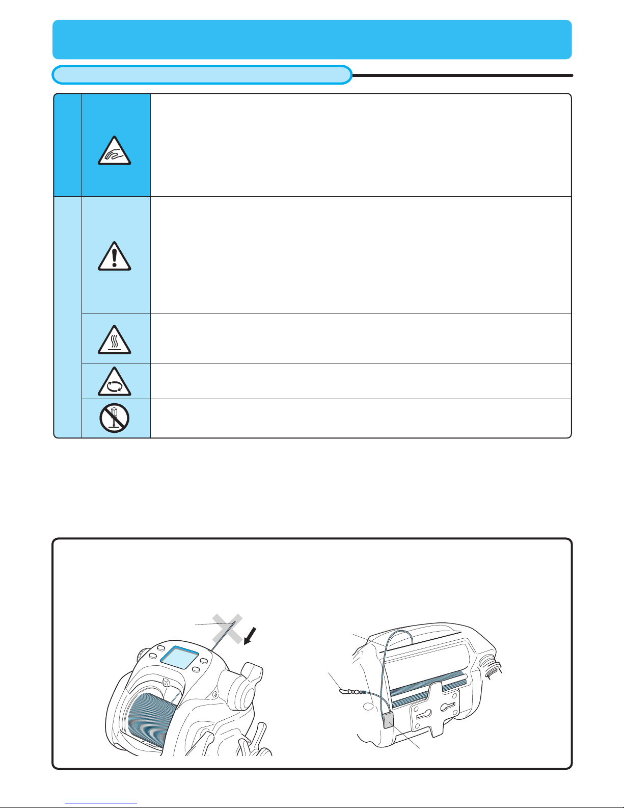
end of the line
line clip
snap
line
DO NOT allow end of line to be wound onto the spool.This may cause synchronization with the levelwind to
be lost, a condition that can damage the levelwind due to the reelʼs high power output. Should this happen,
line should be removed from spool and rewound.
After each trip, attach line to line clip to prevent it accidentally being wound onto reel.
Caution
Precautions
Warning
Attention
1. When electricity is applied, a weak radio wave is generated and may effect hearing aids, cardiac
pacemakers, and other medical devices causing malfunctions.
Especially for those who use a cardiac pacemaker, the electric reel may cause palpitations and
dizziness, so you should consult the manufacturer of your electrical medical device or the
distributor for the effect of radio waves.
2. Be careful to keep fingers clear of the levelwind mechanism. It can pinch your fingers and cause
injuries.
3.While feeding the line (with the motor on), the line may be caught in the reel when the clutch is
turned on. Be careful not to have your fingers caught in it. Injury may result.
1. If your sinker or lure is caught on the bottom, cut your line rather than jerk the rod to free
it.(Protect your hands with gloves or a towel.)
2. After fishing, rinse and dry the reel thoroughly. Store in a dry place.
3. Handle the reel with care. Dropping it may cause damage.
4. Do not touch the line while reel is running. It could cut your skin.
5. Use this reel for fishing purposes only.
6. Be careful not to get reel grease on your clothing.
7. Do not use metal wire for the main line.
8. Dropping or other shocks to the reel may cause the reel or internal electronic components to
break, leak, crack or malfunction due to short circuit.
Do not strongly jar or apply heavy pressure when in use.
1. Do not disassemble the reel. It could result in malfunction that could damage the reel or cause
personal injury.
1. Do not touch moving parts while the reel is operating or it may cause injury.
2. Drag adjustment should only be done with the auto winding functions off.
1. When you use a power source other than the battery or the power source provided by the boat,
be sure it is of the proper voltage. Excess voltage will harm the reel and may generate enough
heat to burn your hands.
2. A heavily rusted cord may generate heat, so please do not use it.
1
Do not reel in the end of the line
About the counter display
The following conditions may make the display difficult to read.
1. Wearing of polarized glasses.
2. Excessively cold or hot weather, mid-winter (displayʼs surface temperature is below -10 degrees
centigrade) and mid-summer (displayʼs surface temperature is above 60 degrees centigrade).
3. When light strikes the display from certain angles, the displayʼs digits may have shadows. This does not
affect its function.
2
Power source
How to connect the reel to the power source
About the power source
Battery indicator
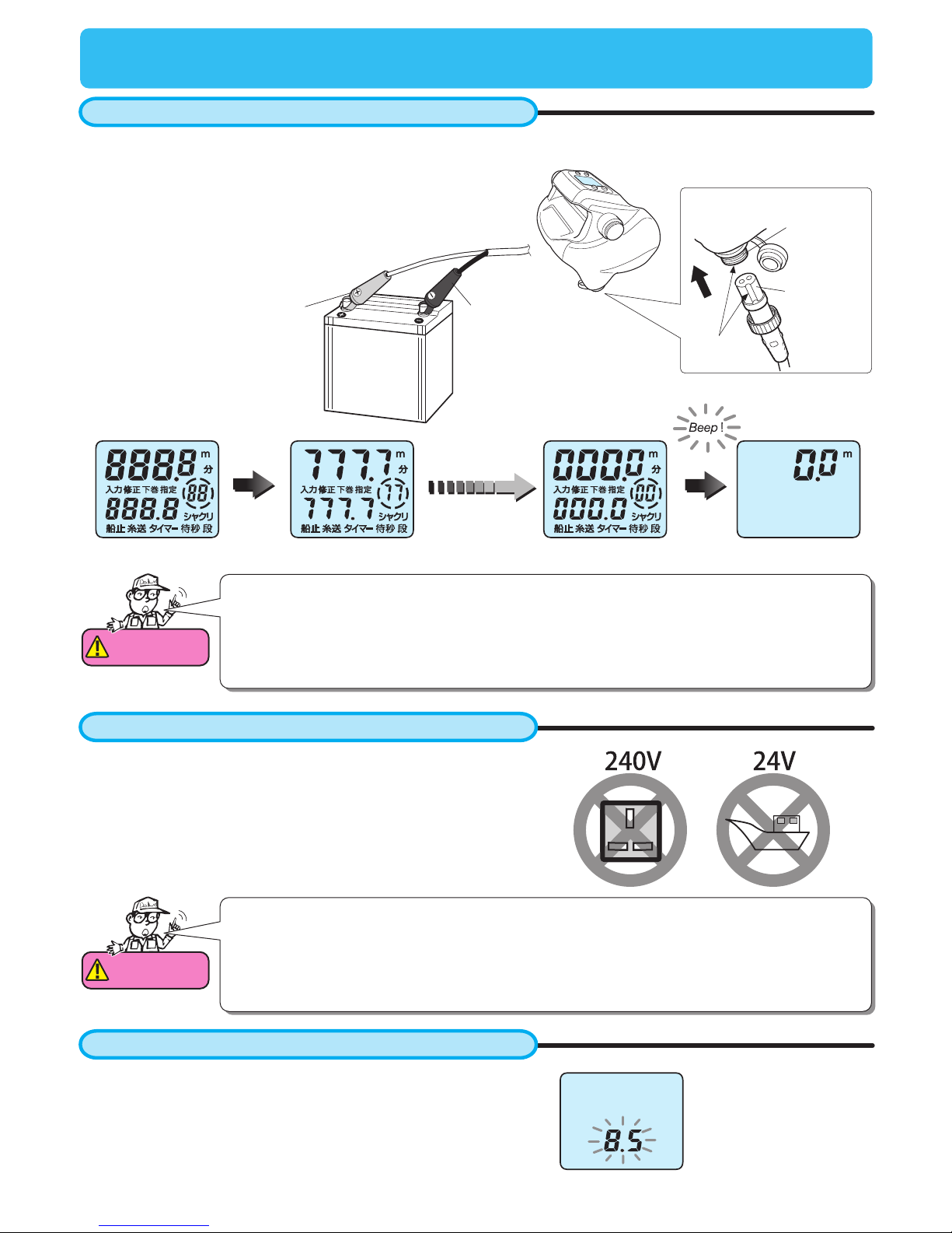
1. Attach the cord clips to the battery. Red covered clip is the plus
(+), and the black covered clip is the minus (-).
2. Insert the connector into the reel. After this, the display
appears as below.
This reel is made to accept DC 12 Volt power only. Power sources
providing other than this cannot be used.
The power provided by a boat can be unstable, causing the reel to
stop unintentionally. Please use a battery made specifically for
fishing reels, such as our Energy Pack.
With power on, digits of the inverse counter (counter in the lower
area) will blink if voltage gets below DC 9 V.
If the display shows this when the motor is not running, then
battery voltage is likely to be low. In this case, replace the battery
with a recharged one.
0.5 sec
Attention
1.When changing batteries, the display’s backup memory stays active for about 10 minutes
after the old battery is disconnected. Thus the above display startup sequence does not
need to replay when the new battery is connected within the 15 minute time frame.
Attention
Make sure of the following before departure.
1. Recharge the battery before your fishing trip. Over time, a battery can naturally discharge.
2. Confirm the boat can provide the proper power source (i.e. voltage, connector shape etc).
3. Corroded connections can prevent the flow of electric current. Remove any corrosion or
dirt from the connectors.
This figure shows the
voltage is 8.5 V
Black
Red
Match slot
with key
Main bodyʼs
power supplier
Connector
3
Using the Reel
About the counter display
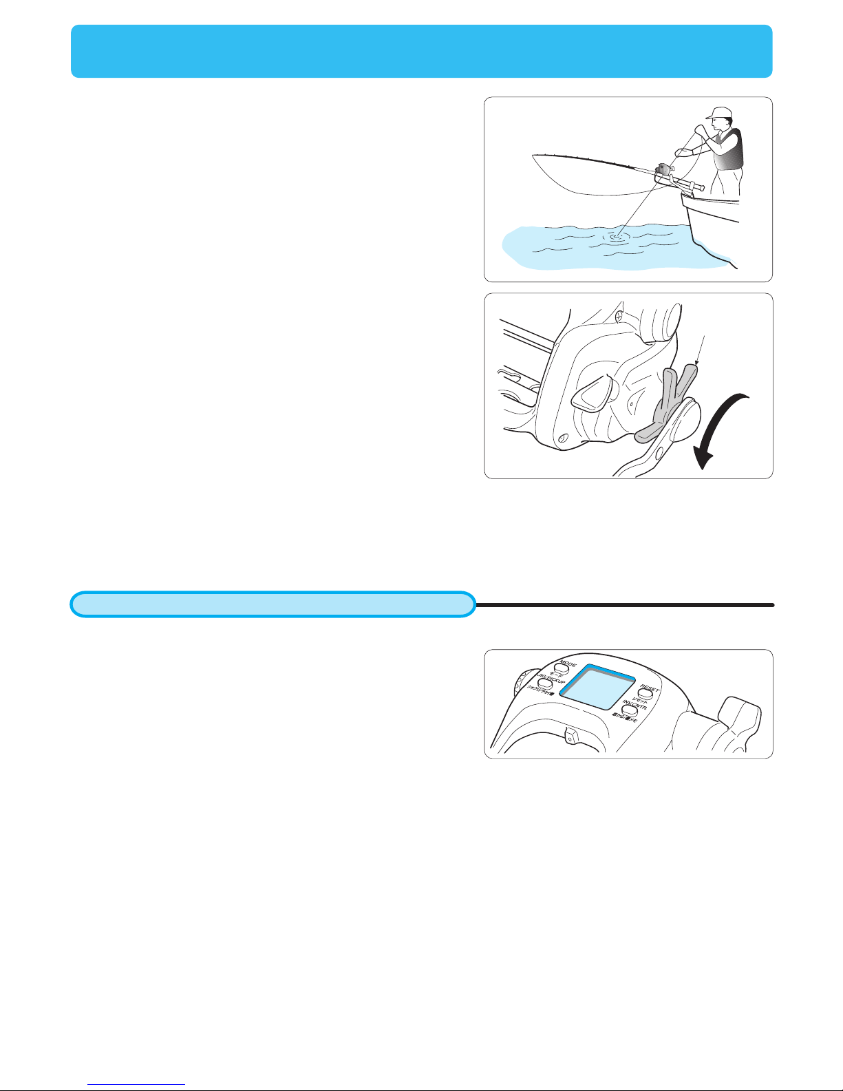
1. Do not jerk your rod to free a lure or sinker stuck on the
bottom. Pull the line taught with a gloved hand and cut it.
2. After maintenance, be sure to loosen the drag and store the
reel in a dry place.
3. Handle the reel with care to avoid dropping and possibly
damaging it.
4. Do not use metal wire as the reelʼs main line.
The following conditions may make the display difficult to read.
1. Wearing polarized glasses.
2. Excessively cold or hot weather, mid-winter (displayʼs surface
temperature is below –10 degrees centigrade) and mid-summer
(displayʼs surface temperature is above 60 degrees centigrade).
3. When light strikes the display from certain angles, the displayʼs
digits may have shadows. This does not affect its function.
1
2Tournament
Drag
loosen
4
Maintenance
About maintenance
Maintenance procedure
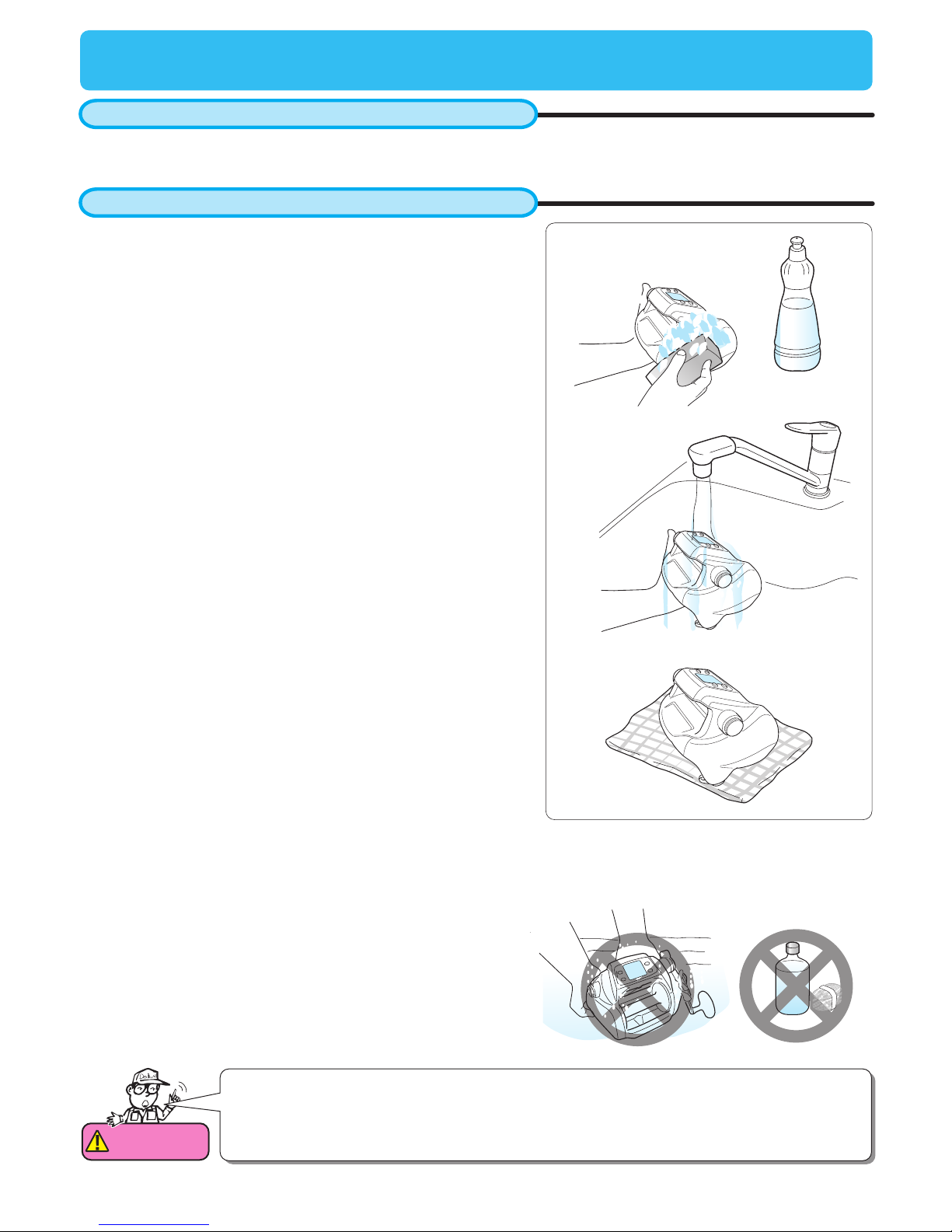
This is a washable reel. Wash away salt residue and grit after fishing
1. Wash the reel with a dish washing detergent and a soft
sponge. Do not use solvents.
Attention
1. Do not submerse the reel when washing.
2. Do not use organic solvents such as benzene and thinner.
3. Do not use a steel brush or abrasive cleanser.
1
2
3
3. Dry the reel well.
2. Rinse detergent and dirt away with running water, rinsing the
spool very well to get rid of salt. Use warm water, under 30
degrees centigrade.
Do not use soap or other detergents. Other soaps or solutions
may damage the reel both externally and internally. The
solution may damage the outside coating of the reel and may
breakdown the grease inside of the reel creating an overflow of
grease.
5
Handling and maintenance of the power cord
Maintenance of the power cord
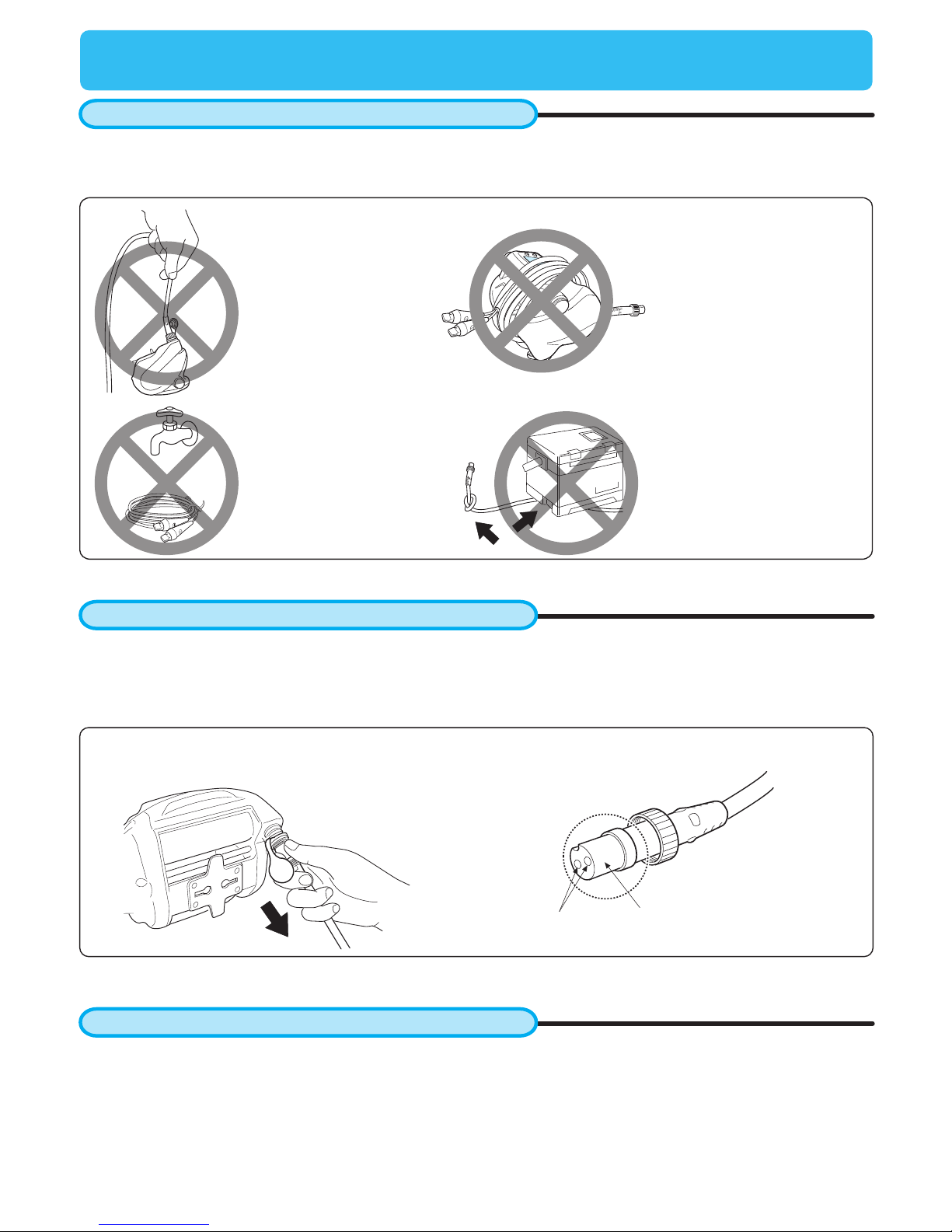
Follow the restrictions below to avoid cord problems. Do not cut or connect your cord by yourself as it can cause
unintended problems.
- Wipe the power cord with a wet cloth and dry it well.
- Pay special attention to drying the tips, with cover removed.
- Grease the connector after it is dried.
- Disconnect the power cord from the reel before storing.
Other maintenance points
- This reel is a precision instrument that employs electric circuity and motor. Do not disassemble the reel by
yourself.
- Cover the power connector on the reel with its protection cap.
- Old or worn cords can cause a bad connection and/or short circuit. Replace the cord every 2 years.
AB
Hold the connector, not the power cord, to pull the power
cord from the reel
Do not hang the reel
by the power cord.
Do not wind the power
cord around the reel
body with the connector
inserted into the reel.
Do not wash the power
cord.
Do not set heavy items
on the power cord, or
tie knots in the power
cord.
Maintenance
Clean and grease area A (pins) and area
B (Circumferential area).
6
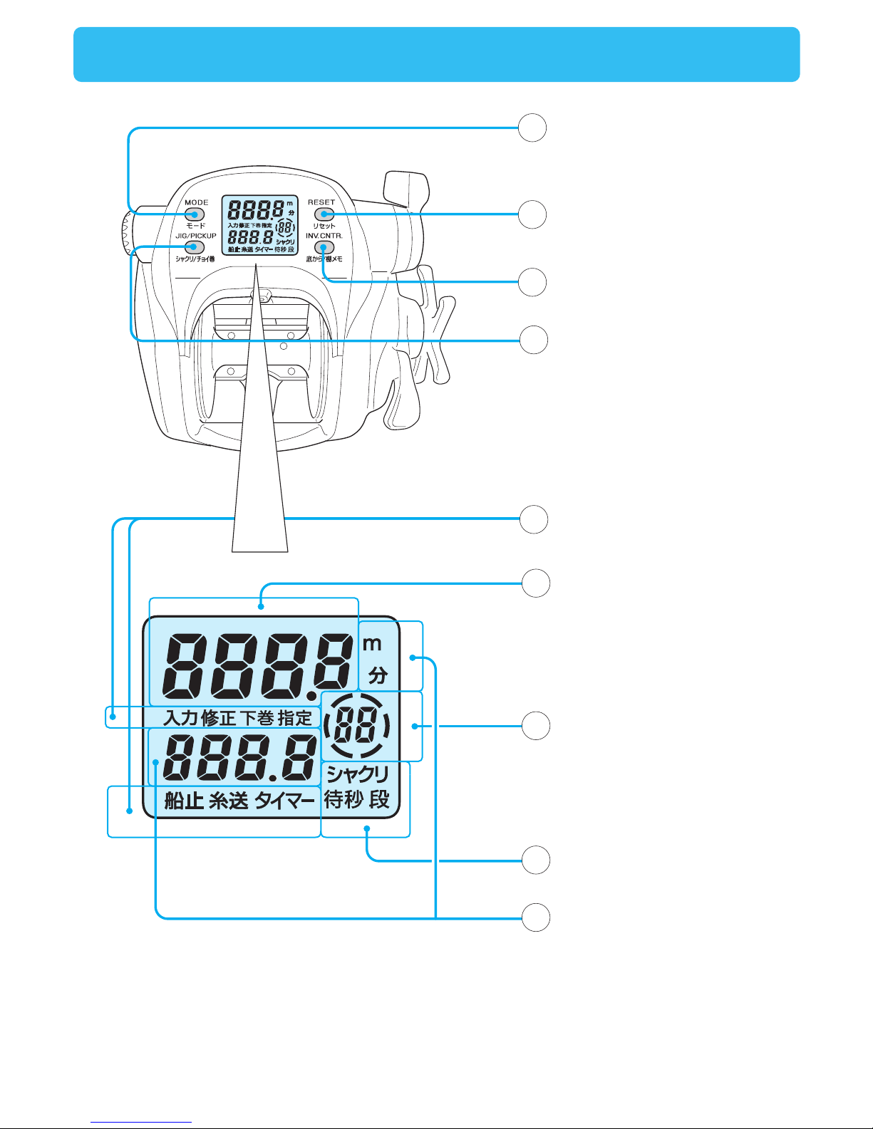
Names of the buttons and the display
5
9
8
6
7
MODE BUTTON
RESET BUTTON
INVERSE COUNTER BUTTON
JIG/PICKUP BUTTON
Mode display
Depth counter
Inverse counter
(winding speed display)
Jigging display
Chumming timer
(Power indicator,
time to wind up,
timer display)
1
4
2
3
7
MODE BUTTON
Press the MODE BUTTON to scroll through the adjustment displays for each reel function.
- Use the Power Lever to adjust numeric values.
- Pressing the MODE BUTTON sets the numeric values you have adjusted.
- Depress and hold the MODE BUTTON to return to the depth display.
- Mode change cannot be done while line is being fed.
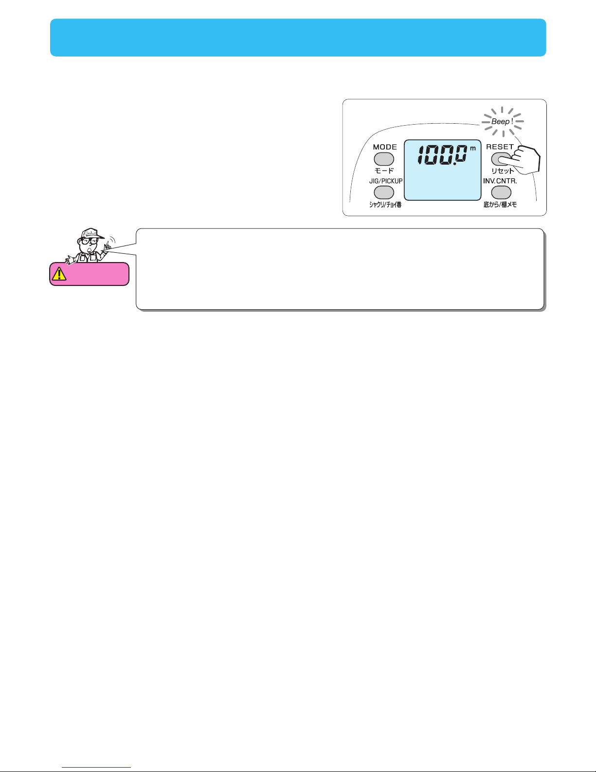
RESET BUTTON
This button resets the depth counter to zero.
Make sure to press this button before you start fishing. The reset depth is used to make the auto stop function
work. (display shows ). The default setting of auto stop is 2 meters.
To prevent an operational error, the RESET BUTTON needs to be pressed for more than 2 seconds with the setting
of 10 m or more.
This prevents accidental resetting. For a total reset, when line has been broken off, press and hold the button for at
least 2 seconds.
INVERSE COUNTER BUTTON
Pressing this button resets the counter in the lower area of the display.
- It memorizes distance from the bottom, handy for dropping a bait right back into the strike zone after youʼve been
bit.
- The chumming timer resumes after pressing this button.
JIG/PICKUP BUTTON
Selection between pickup and jigging can be done in the mode setting display.(One of them should necessarily be chosen.)
Pickup
-You can wind only while pressing this button. This function is useful to wind up line slack and attract fish.
- Winding speed can be changed with the mode setting display. (Default setting is speed 15)
Jigging
- Jigging can be ON/OFF.
- Pressing this button starts jigging. (Display shows )
- Pressing the button again stops jigging.
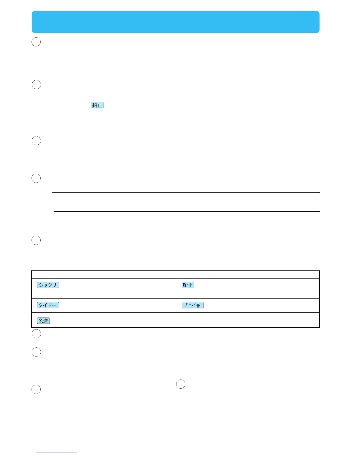
Mode display
- This display allows you to change setting of each function.
- The functions that are set to work are shown on the display.(Default setting is speed 15, but the speed can
actually be set between 0~Hi.)
Depth counter
- It shows the depth from the surface.
Chumming timer (Power indicator, time to wind up, timer display)
- The chumming timer appears when motor rotation is stopped.The timer display cannot be set to OFF.
- While using the power lever, the power level is shown.
- While the electric winding up is in action displaying actual winding speed, the timer indicates the remaining time to
auto stop at the ship side(in minutes and seconds).
Jigging display
- This is appeared only when the jigging function is on.
- It blinks when jigging is in process.
Display Function Function
Display
Pressing the JIG/PICKUP BUTTON
makes the function work. Pressing the
button again stops it.
Chumming timer starts working.
Auto Line feeding is employed. Default
setting is off.
Pressing the RESET BUTTON makes this
indicator appear, telling you auto stop will
work.
Only while pressing the JIG/PICKUP
BUTTON will the motor run to wind line.
Names of the buttons and the display
1
5
9
8
4
6
7
2
3
Inverse counter (winding speed display)
- This counter shows the depth from the bottom (or a
certain depth).
- Once this counter is turned on, its display cannot
be turned off.
- While winding up, winding speed appears in meters
per minute.
(The display of winding speed can be set to OFF)
8
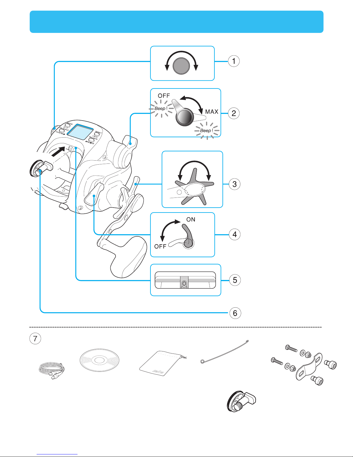
Names and functions of each part
weak strong
loosen tighten
Free spool adjustment
Waterproof drag
Power lever
Clutch
Levelwind
Input Roller
Enclosed items
Manual CD-R
Power cord Storage bag
Levelwind threader
Input Roller
Rod Clamp

9
- It adjusts brake tension on the spool to prevent backlash or line slack caused by dropping the line with hook and
sinker.
- You can freely adjust winding power, or winding speed, from zero(ON/OFF) to maximum, by 32 steps, by using
the lever.
- Tilting the lever forward adds power and speeds up the winding.
- Pulling the lever back slows down the winding.
- Without the lever positioned to OFF, it is impossible to start winding. You have to pull it back to the OFF position
before you start winding. An audible sound indicates the OFF position.
- The power lever is used to set numerical values on the various function displays.
- Adjusting the star drag allows the spool to slip against a strong pull to avoid line breakage.
(1) Adjust the drag while reel is on the rod and the line is strung through all the line guides.
(2) Adjust drag with the clutch ON, while pulling the line with your hands. Normally, the drag is adjusted to prevent
the weakest line in the line system from breaking.
- Turning the handle automatically engages the clutch.
- ON position > line winding can be done.
- OFF position > spool is free-turning to let out line.
- The levelwind distributes line evenly on the spool as you wind it in.
(Under some special circumstances line may not wind evenly because of the clearance between the levelwind
and the line.)
Names and functions of each part
1
5
4
6
7
2
3
Input Roller
Enclosed items
Levelwind
Clutch
Waterproof drag
Power lever
Free spool adjustment
- Power cord
- Manual CD-R
- Storage Bag
- Levelwind threader (This tool simplifies threading line through the levelwind.)
- Input Roller
- Rod Clamp
- Put the rough sides together and fix in place with screws. When installed and connected to the power, it will set to
Automatic Input mode.
10
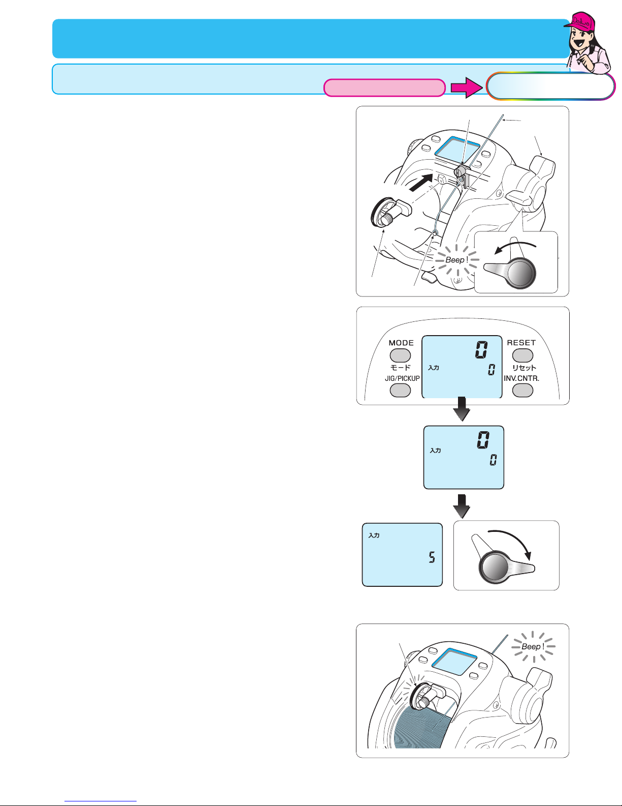
Input Roller
Line data input (with Input Roller)
You can also set the main line utilizing the Input Roller.
6
1
4
5
MAX
Levelwind Guide Main line
Pin
Power lever
Input Roller
4. Attach the Input Roller, sold separately, to the reel. You will
then hear a beep sound confirming that the reel enters then into
the Automatic Input mode.
Tighten the drag to give enough line tension in order to wind line
without slipping
1. Run the line through the Level Wind Guide and tie it onto the
spool.
The Levelwind Threader, one of the accessories, makes this
process easier.
Make sure of tying the line onto the Thread Pin to avoid the line
slipping on the spool surface.
2. Connect the battery to the reel.
3. With the reelʼs power on and the display showing 0.0,
press the MODE BUTTON for more than 5 seconds.
5. Push the Power Lever forward to maximum and wind the line.
When the Power Lever is moved forward, number on the lower
rigth portion of the display changes into a tension indicator, and
number of the counter on the upper portion of the display
begins to increase.
Keep line tension between level “5” and “7” while winding the line.
6. Continue line winding until the line touches the Input Roller.
When the line reaches the Input Roller, the latter begins to rotate
so that the winding may stop automatically.
2
OFF
3
4
-Note that the value of tension between 5 and 7 simply displays
an appropriate value with the power lever at MAX. When wound
at a low speed, the display shows that a high tension is applied,
so please be careful since it may cause trouble.
As line winding continues, the displayed number of the counter
increases.
Line data input
With lnput Roller
See animation
11
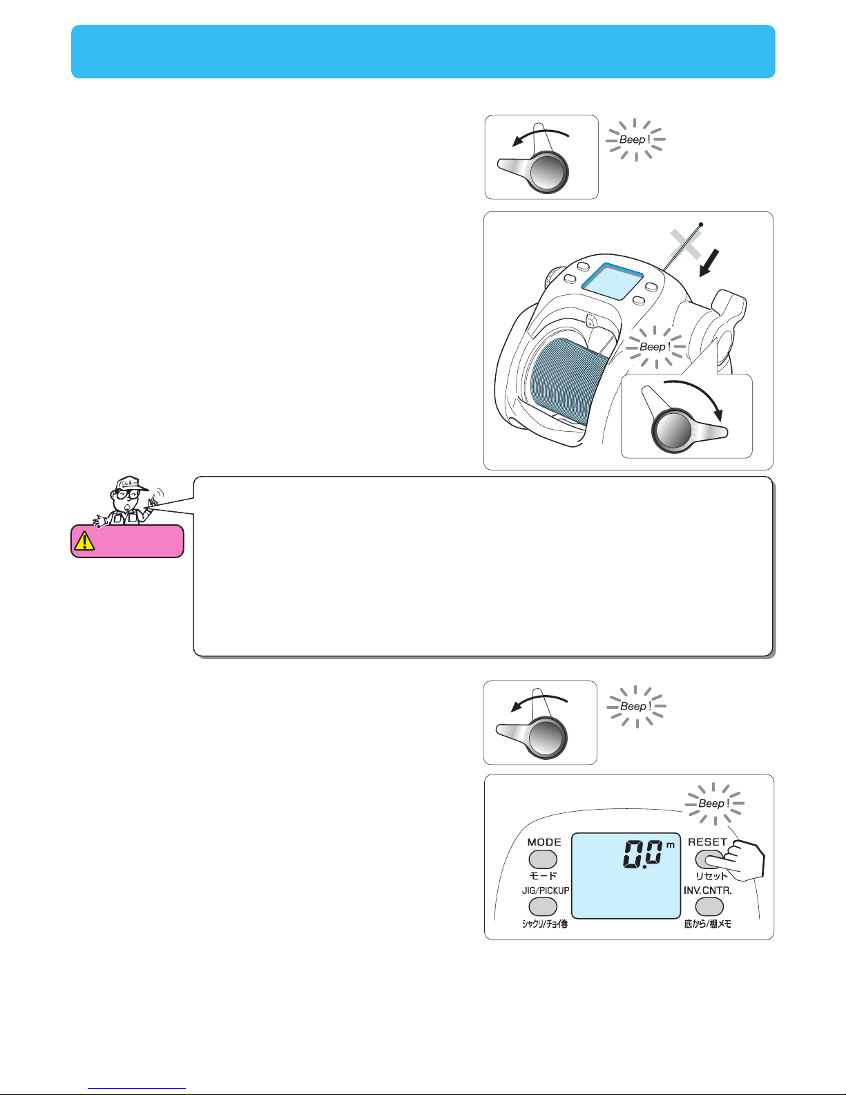
9Do not reel in the end of the line
MAX
OFF
8
7. Take off the Input Roller.
8. Pull the Power Lever to the OFF position once again. (The
beep will then be heard.)
9. Push again the Power Lever forward to maximum and wind the
remaining line to fill the spool.
Be careful not to wind up the end of the line because it may cause
an error.
Line data input (with Input Roller)
Attention
1.Do not allow line to rub against the finger guard while winding as it will scratch the guard.
2.
When the line is wound indoors for a long time (15 min. or more) at a high tension, the
motor may heat up abnormally and cause problems, such as deterioration of winding
power, speed, etc., so electric winding is stopped automatically. Input line at as a high
speed as possible. When actually fishing, there will be no problem because it is cooled
down with sea water, etc. When it stops, wind up manually or pull the power lever back
up and down again towards the MAX side to rewind it and re-input line.
3.Do not wind the end of the line onto the spool because it causes incorrect length
calculation. Move the power lever to OFF, and wind manually when nearing the end of the
line.
OFF
10. Pull the power lever back to the OFF position when only
about 10 m of the line to be wound remains. (This will stop
electric winding.)
(Alarm sound)
11
Should “Err” appear on the display, then use the MODE SET
BUTTON to re-enter the data.
11. When the line is wound until the position just before the end,
press the RESET BUTTONRESET BUTTON for more than 2 seconds. When you
hear the alarm sound and the display shows 0.00.0, the line data
input is complete.
Line’s end
12
Attention
1.Do not allow line to rub against the finger guard while winding as it will scratch the guard.
2.The motor can be overloaded when winding at very high tension for a long time (about 15
minutes). In this case, the motor will automatically stop. This does not occur while fishing
as water helps cool down the motor. If the motor stops, wind manually or move the
power lever momentarily back to OFF and then resume winding. Wind the line at high
speed (less tension).
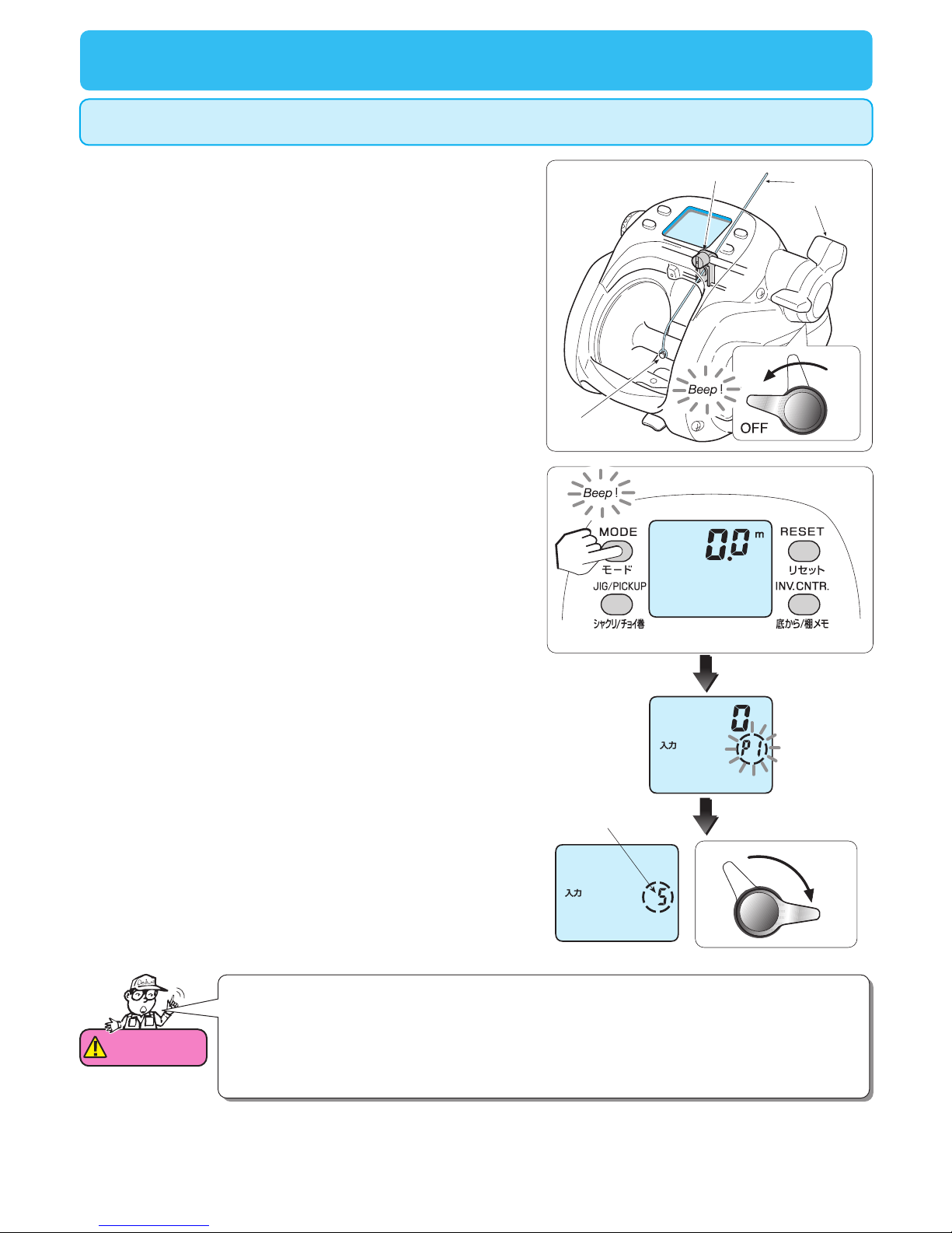
Line data input
(When line length is known---P1)
This method is used when the line length is known before winding. In the example below,
PE 6 – 700m is wound.
1. Run line through the levelwind guide and tie it onto the spool.
The levelwind threader makes this process easier. Make sure to
tie the line onto the pin found on the spool to avoid the line
slipping.
4
MAX
1
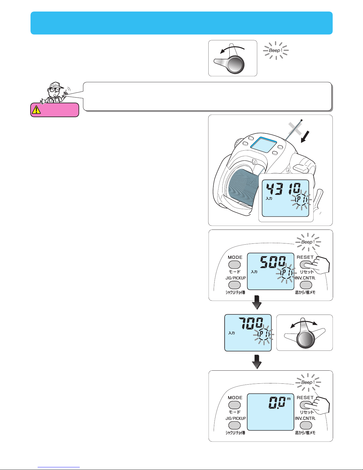
4. Push the power lever forward to maximum and wind the line to
its end.
As the power lever is moved forward, the P1 display changes to a
tension indicator. Keep line tension between level 5 and 7 while
winding on line.
2. Move the power lever to the OFF position.
3. With the reelʼs power on and the display showing 0.0, press the
MODE BUTTON for more than 5 seconds.
Make sure the drag is set firmly.
3
Tension indicatar
Levelwind Guide Main line
Pin
Power lever
2
Note that the value of tension between 5 and 7 simply displays an
appropriate value with the power lever at MAX. When wound at a
low speed, the display shows that a high tension is applied, so
please be careful since it may cause trouble.
13
Attention
Do not wind up the end of the line. Turn the power lever at OFF position before the end
(stop electric winding), and wind up the remaining line manually. When the end of the
line is wound up electrically, it may cause an error on the counter.
7MAX
OFF
OFF
5
6
8
6. When the line is wound until the position just before the end,
press the RESET BUTTON for more than 2 seconds, until the
display shows 500. (Default value is 500). The value may be
different once it is reset.
5. Pull the power lever back to the OFF position when only about
10 m of the line to be wound remains. (This will stop electric
winding.)
(Alarm sound)
7. Enter the line length with the power lever. (in the figure on the
right, line length is 1000 m).
(The value increases/decreases with operation of the power lever.
The right figure is when it is set to 700 m.
8. When set at the length wound, press the RESET BUTTON for
more than 2 seconds.
If “Err” appears on the display, you must use the MODE SET
BUTTON to re-enter the data.
Do not reel in the end of the line
Line data input
(When line length is known---P1)
8. Press RESET BUTTON for 2 seconds and a beep will be
heard. The display should return to 0.0, completing the setting
procedure.
Line’s end
14
Main line
Backing line
Tie
3
Line data input (With backing line---P2)
This method requires use of Daiwa braided line that is color coded to show length and has a total
length greater than 100 m.
1
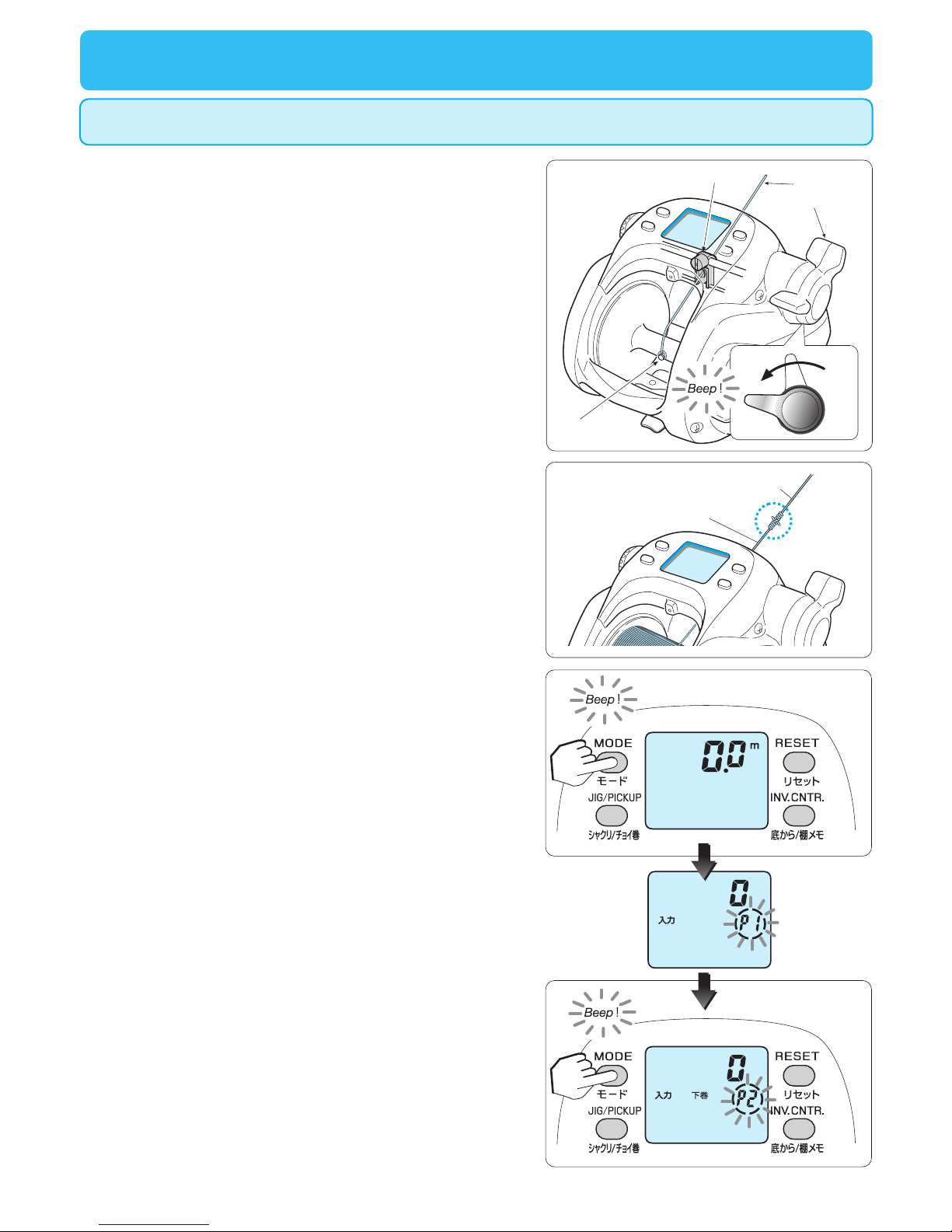
5. When P1 is blinking, press the MODE BUTTON to display the
screen for P2 backing line input.
It turns to P2 mode and P2 blinks.
4
5
1. Pass the backing line through the hole of the Levelwind to be
tied onto the pin found on the spool, and then turn the power
on.
The levelwind threader makes this process easier. Make sure to
tie the line onto the pin found on the spool to avoid the line
slipping.
2. Wind the backing line.
If the power lever is not already at OFF position, then pull it
back to OFF position before beginning to wind.
3. When the backing line is wound up, tie both ends of the lines
securely.
(Prepare to wind up the main line.)
4. Press the MODE BUTTON for 5 seconds, when the display will
show 0.0.
It turns to P1 mode and P1 blinks.
Levelwind Guide Main line
Pin
Power lever
OFF
2
15
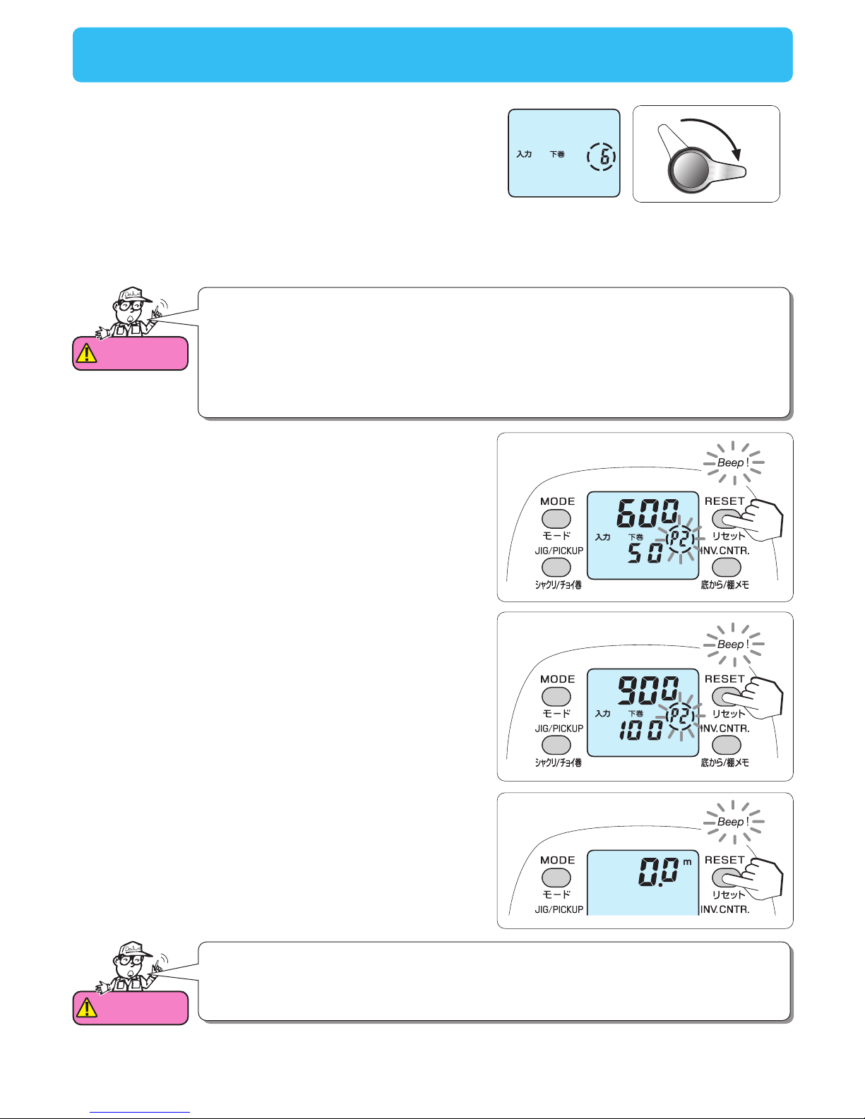
11. Press RESET BUTTON for 2 seconds and 0.0 will appear.
This is the end of the procedure.
11
7
9
6
MAX
Attention
1.Do not allow line to rub against the finger guard while winding as it will scratch the guard.
2.When the line is wound indoors for a long time (15 min. or more) at a high tension, the
motor may heat up abnormally and cause problems, such as deterioration of winding
power, speed, etc., so electric winding is stopped automatically. Input line at as a high
speed as possible. When actually fishing, there will be no problem because it is cooled
down with sea water, etc. When it stops, wind up manually or pull the power lever back
up and down again towards the MAX side to rewind it and re-input line.
6. As indicated by the lineʼs color coding, wind the line up until the
remaining line is 100m.
With the power lever moved forward, P2 changes into a tension
indicator.
Adjust the tension to between 5 and 7 on the right side of the
panel.
7. Press RESET BUTTON for 2 seconds.
P2 blinks again and the lower counter shows 50. The upper
counter digits increase as line is wound.
8. Wind on another 50 m of line, keeping line tension at the
suggested level.
(Be careful not to wind up excessively.)
-Note that the value of tension between 5 and 7 simply displays
an appropriate value with the power lever at MAX. When wound
at a low speed, the display shows that a high tension is applied,
so please be careful since it may cause problems.
9. Press RESET BUTTON for 2 seconds.
The lower counter shows 100.
10. Wind the remaining 50m, keeping line tension at the
suggested level. Do not wind line all the way onto the spool.
(Be careful not to get caught in the reel.)
Attention
Do not wind the end of the line onto the spool because it causes incorrect length
calculation. Move the power lever to OFF, and wind manually when nearing the end of the
line.
Should “Err” appear on the display, then use the MODE SET
BUTTON to re-enter the data.
Line data input (With backing line---P2)
16
Line data input (Backing line 2---P3)
This procedure is to enter the line length after it has been wound onto the reel. It is necessary that
you know the line length and that it is greater than 100m.
2
3
5
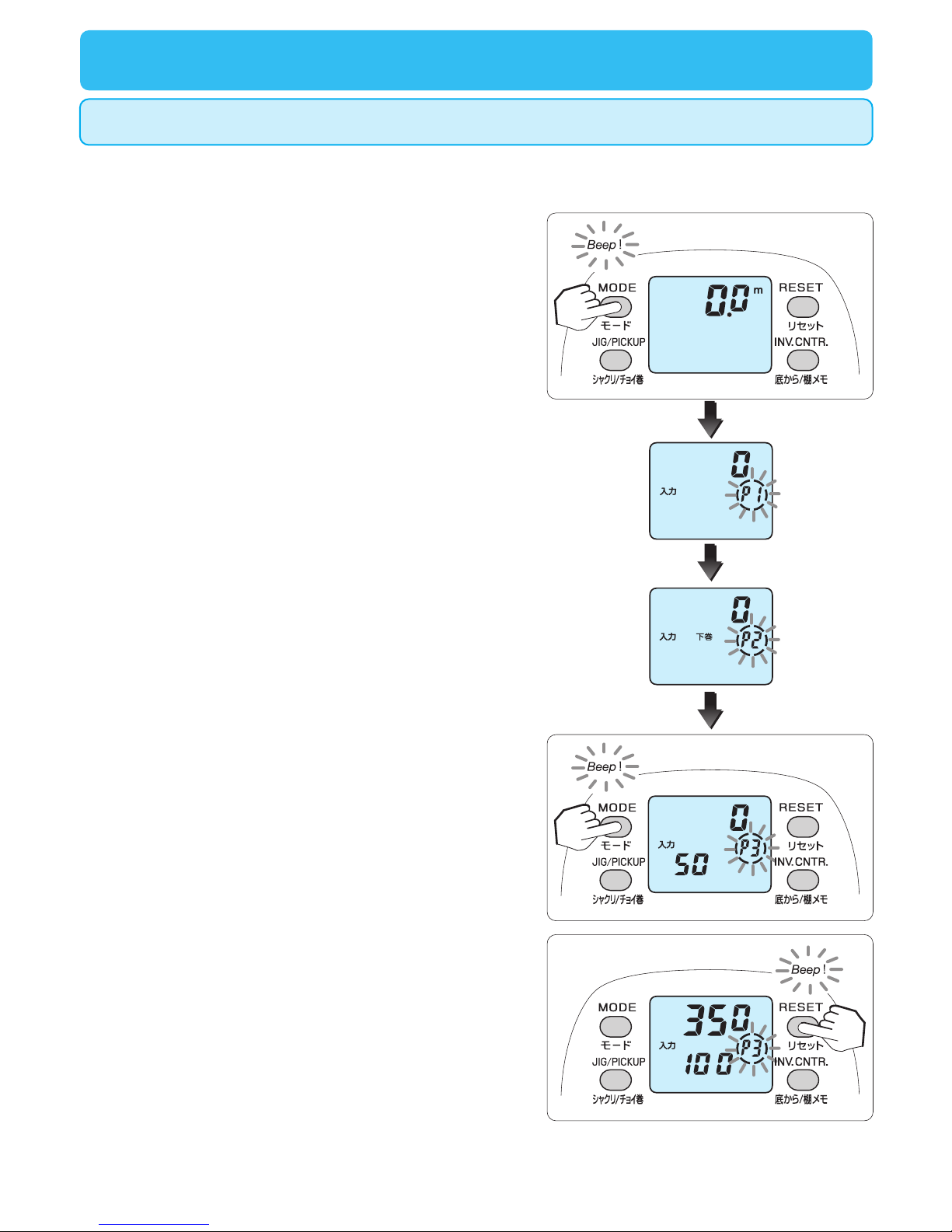
4. Paying attention to the lineʼs color coding, pull 50m of line off of
the spool.
(The number of the counter above increases.)
1. Turn the power on while the main line is wound up.
2. Press the MODE BUTTON for more than 5 seconds while it is
indicating 0.0.
It turns to P1 mode and P1 blinks.
3. Press the MODE BUTTON 2 more times to display the display
of P3 Backing line 2.
It turns to P3 mode and P3 blinks, with a display of 50 in the lower
part of the counter.
5. Pull out 50 m of line and then press the RESET BUTTON for
more than 2 seconds.
This will show the digits 100 in the lower area of the counter.
17
7
Should “Err” appear on the display, then use the MODE SET
BUTTON to re-enter the data.
6. Pull an additional 50m of line from the spool.
7. Pull out additional 50 m of line and then press the RESET
BUTTON for more than 2 seconds. (The line is pulled out for
100 m in total.)
It displays 100.0 and this is the completion of the input procedure.
8. Wind up the line.
(Apply the auto stop function when winding up using electrical
power.)
Attention
1.Do not wind the end of the line onto the spool because it causes incorrect length
calculation. Move the power lever to OFF, and wind manually when nearing the end of
the line.
2.When you input data following this procedure, there are cases in which the length of line
will not be displayed if exceeds 100 m, but this is not a problem. In this case, try another
input method.
Line data input (Backing line 2---P3)
18
Functional setting operation
(1. Mode setting display)
1.There are many useful functions in the mode
2.While the mode setting display is on, operate the power lever to change it to a desired value, and
then press the MODE BUTTON to complete the procedure.
3
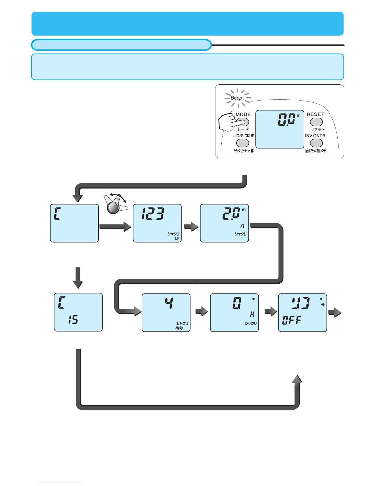
How to set the many functions available
1. Press the MODE BUTTON to choose a display.
Each press of the MODE BUTTON changes the display to the
next function.
Holding the MODE BUTTON down, rapidly scrolls through the
displays, quickly getting you back to the depth display.
At each mode setting display, the default setting can be
retained by pressing the RESET BUTTON.
While letting out or winding line, the MODE BUTTON cannot be
used to change settings.
Power lever MODE
BUTTON
MODE
BUTTON
MODE
BUTTON
MODE
BUTTON
MODE
BUTTON
Jigging range Winding speed display
(Each display example is the default setting)
This is displayed when the MODE BUTTON (1) is set to pickup.
When it is set to jig, it displays the jigging pattern (2).
(It depends on the setting.)
Jig/pickup pattern Jigging pattern Jigging length
Pickup speed Jig waiting time
(Select the indicator
of either the measured
winding speed or the
inverse counter.)
Table of contents
Other TANACOM Fishing Equipment manuals

Popular Fishing Equipment manuals by other brands

Avet Reels
Avet Reels Single Speed Reel SX 5.3 parts list

Renzetti
Renzetti Presentation True Rotary 3000 Series quick start guide

ProLogic
ProLogic Fulcrum RMX-Pro instructions

Shakespeare Electronic
Shakespeare Electronic SPINNING REEL owner's manual

VEXILAR
VEXILAR FL-8SLT Operation manual

Avet Reels
Avet Reels Fishing Reel MXL - 6/4 parts list


