Tanaka K2-1701 User manual

ЛL「 K=°
Sewice Manual
for DiJtd B100d Pressure Mo tor
Model No.K2‑1701

1.
2.
3.
4.
5。
6.
INDEX
DescP■on.… ……
…
……
……
……
……
・
・
……
……
…
…………
。
・
Speciflcati9ns
Princioles Of Operation..… ………
…
…………
…
……
……
…
…
……
・
Operating lnstructiOn.… …
………
…
…
……
………
…
・
・
…
…
…
……
…
…
…
El‐ror Display
Out Side Drawlng
6,1.l ail■ Unit
6‑2i Cuff Unit(Starldard cuη …
.… …
…
Production PrOcess Table
Pressure Sensor.… ……
..
Pressure Test Ⅲ
…
……
....・・
…
…
・・
・・
…
―
…
¨
…
…
…
・
・
…
…
……
…
2
3
5
0
2
1 1
3 4 5
1 1 1
9
0
1
2
3
1
2
2
2
2
7.
8.
9
6 7
1
1
1 2
1
1
10,Exploded Views
10‑1.Main Unit
10‑2Cuff Unit.… …
Ⅲ
..
10‑3.Packing。 ¨I。 …
....… ……
……
…
……
…
…
…
…
……………
………
・
Parts List.… ¨..… ……
・
・
¨
……………
…
・
・
…
…………
…
……
……
Trouble shooting。 …
…
…
…
……
…
…
………
…
…
…
……
………
…
…
…
…
・・
……
1

1。 DeseriptiOn
THE MODEL DS‑135‑03 is a Manual Lttauon Digital B100d Prcss■ Lrc MonitOr.
Tl■ e readings in each inctiOn are dlgltal dlsplayed on LCD panel.
STATUS INDICATION shows Denation,団 atiOn,PulseヽVavc and Battclyヽveak.
ERROR MESSAGE CODE ll■ cludes Battery Weak,it is力 mpossible to meastlre .
thc blood Pressure accuratcly. ´
BATERY POWER is monitOred when the unitis tλ rned on and a wttnmg
ゝ江
u be displaycd ifitis t00 weak. .
MEASURING SEQUENCE is displayed to inte lllccessay Opcration by tlle user.
They are;
Dёflaton:Wait untilinflatiOn Or dullnp the cufF pressure.
団at■ On:Pressuコに
cthe cS、
援、
織
出
l需粍蹴
up」 ぬC pulsc口 ら
"geL∝
血e nashing
TIII:11011:皿 ::l:IIFIIIF:f ifit i:hot operated for about 180 sccOnds Or inore
2

2,Specirlcations
2‑1.MOdel DS´135‑03
2‑2.Classiflcauon CttS Ⅱa
2‑3.Function O BloOd Plessure Measunng
②Pulsc Rate Measu g
O Automatlc POwer Shut off
0 3 ErrorlndicadOn
2‑4.BP.M.Speciflca● Ons
(1)Mcasu g Mettod
(2)Measu g PositiOn
Cuff Oscmo―leLic
Upper Anu
(3)COverage arIIl ctctulirence
(4)PresSure detcctiOn
(5)PresSure indicating
(Cuff Prcssure〕
22011nm〜 320mln
Prcssure to Frcquency Convertcr
①Uts IIrLIllHg
②Ra■ gc 0‑300 111ulHg
O Resolutlon lnlmHg
O Zero setting Automadc zero scttg
(6)Measu■ ■g rangc
(7)Accuracy
O Systouc 50‑250111■ IIIIIg Cufr PresstLrC
O Diastolic 40‑180 mmHg Cur Pressure
SYS―DIA>10mmHg
O Prcssurc 士3 mIELHg
②Pulse rate ±5%of Rcadil■ g
(8)C■lfF i■lauon
(9)Preset pressure
(10)CluF deflatiOn
(10)Deflation rate
Squeeze Bulb
18011111111Hg
C?nStant Att Relcase Manual Valvc
20〜 5.O mmIIg/seC(Nomina1 3.5 1nmHg/sec.)
(11)Rapid Exhaust Automauc Exhaust(EV)
(121 Cuf「 wstem O CufFof UppcrハJm
②Lock‐ing Mech― Velcro
O Bladder sレ e130 mm P′ )X230 11nIIIl lD)
O CuffSレe147 111tII1 0″ )× 500 11111rl(D)
3

(13)LdicatOr
(14)Memo7
9 Digtts+4 Statc lndicatOrs LCD.Display
"T銚¬
:蝙。
.
0 4 state lndcatOrs Iniation
DcflatiOn
PalpatOr7 M′ avc
Weak battery
O SystOlic and DiastOhc
0 30 meastlrcment rcsults Xl way
O McmOry Data Average(SYSDIA.)
(15)MicrOCOmputer
(16)Power Source
(17)POwer Consumpt10n
8Bitヽ〔icrocOrrlputcr TMP86CH29BF
R6P,LR6 1ンpe(AA Saセc) 4 pcs.
40mW(MaX)
(18)Operatil■ gTEMP/Humidiサ +10℃ tO+40℃ /15χ 〜
90%RH
SP10 4.4,2.3.A
(19)Storage TEMP./Humidity
(20)Maln u t sizc
乱肝
盟
ダ甘
い65℃ /85%m o4η
150 mttlottЭ 支
1 15 1ELIII(D)× 50.5111m(H)
(21)M twcight APPROX.180 gat oIOt lncludttg Battces}
2‑5.Safety system Cuff Pressurc> 3301111111Hg →Rapid Exl■ aust
2‑6.Electrical safeサ SP10 5.3.2
2‑7.Resistans to vibration&shock SP10 5.2.3.1
2‑8 鮨Lcakage SP10 4.5.2.1
2‑9.Electroma〔昇ctic colnpatibility IEC6060112
2‑19.Stab■ ity Of tl■ e cutt pressure hdlcauOn SP10 4.4,3.4.A, 4。 4.1.4.A
2‑11.overall system accuracy SP10 5.4.5。 B
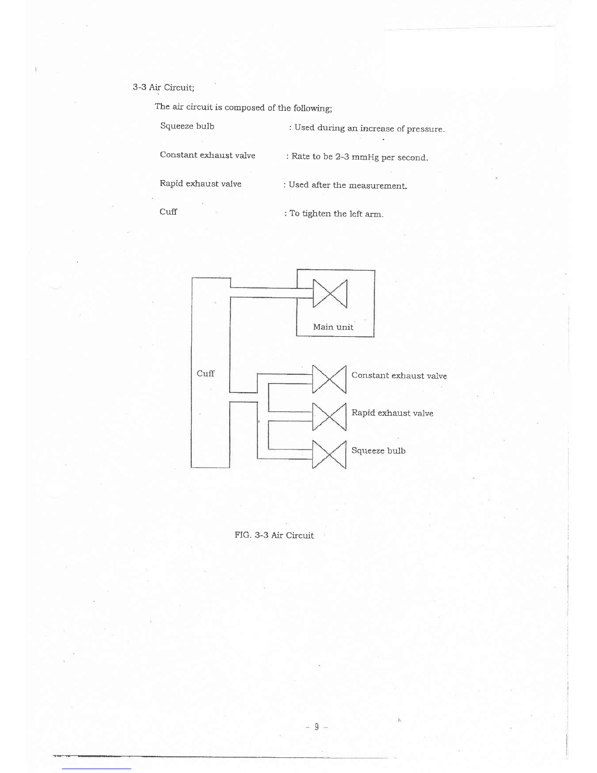
2‑12.Lay a plpe system See"11.ExPloded Vievrs'I P19
2‑13.Operating lnanual Englsh, Spamsh
2‑14.AccscsSorieS Non
2‑15.L e5 Yeal
4

3。 PrinOiples of Operation
3‑1.Operation of Each Unit
Thcse uruts Opcrate as fouows:
C.P.U
ΠG.3‑l Block Diagraul
Pressllre―
Frequency
Converter
Micro―
COmputer
Displリ
Mcmαu Reca■ tttch
Power/Start Stch
Battely
ヽ
〜
reak
Dctcctor Beeper
Battery
‖
R‑6P"Size
4pcs. Power
Control
Ctcuit
F︲ 一C
)r otl■ (
icuits Regulated
3 Volt
P/F Converter
5

al PrCSSure Senso葛
Hastic capsuleCapsule is lnflated by pressurc.
Parallel Plate variablc capacitOr;
Gap Of PTallel plate are changed by innation.
CR oscinator;
oscluation i℃ quency arc changed by capacitance change.
Frequency Co■lnter;
Froquency are cOunted by counter and dlgital outputis took in to the cOmputer.
lThe COunter is lcludcd in tO the computer lc chp)
b)Otllers
Power supply contr01 circuit,
Receives tlle contr01 signal iOm tlle■ tllcrocoIIlputer to t■ lm thc power on and
or to units other●an the crooomputer.
Display Unit;
E)isplays ctlfF pressure,Inaxim■ ■IL blood pressure,IELln」 IIlultl b100d prcssurc,
pulse rate and in面 omation messages.
CI MiCFOCOmputer
鋸
∬
i踏盤1策鳳
m:哩ぶ
:空:1詰冨
『:冨郡
‡薄∫
°nttds he vF∞Ш
c■町
,
6

3‑2 Flow Chart of Opcration
Display chcck
Ter counter>1
Generation of bccper
MeasureIIIlent re
Meastcment
Result Disphy
Pressure Display
pressureP(180mmH
NG
Yes
60msec.X3
7

GeneratiOn of beeper
Prcss■ ■
rc≧ 3301nIIIH
"In■ation"Mark ofF
blood pressu
slve cOndition satis
build up pressurδ
―
sys.>201EIInH
Gellleration of"Hcart'IIlark
and beepcr by pulse wave
LIn■lm b100d pressuI
gecise cOnddOn
B.P.M and Pulsc display
Measuttg fh sh
・Deflation"]Ⅵ ark On
8

3‑3A血
「Circuit;
The air circultis composed of the following;
Squecze bulb
Constant exhaust valve
Rapid exhaust valve
CufF
:Used du g an increase of prcssure
:Iこtc to be 23 mmttg per second.
:Used after the measurement.
:To tighten the lcft aml.
Constalllt exhaust valvc
Rapid exhaust valve
Sqlleezc bulb
FIG.3‑3 Air Cicuit
Main unit
9

4。 Operating lnstructiOn
4‐ l POwer Supply
l)Battely lnsinllatlon
Takc off battcry cover rcar sidc Oflnalll body and
sert 4 Picces Of R 6P or LR‑6 type batterlcs tO flt
polanサ lllLdiCation.
4‐2 Measurement PrOced・
・
res
l)POWer switch On
Please conanII to appear"DeflatiOn IIllark on the LCD pancl、
2)Wrap the cuff around the upper left arrrl
ヽ
乃
rith the rubber tube ofthe cufr positloned in the dlrcction oftl■ e
fmgel過中
s,placc it on the left aral.
Wrap the cufF around tlle aml■ ‐
iLh tlle elge of Culff apprOnatcサ
l inch abovc the elboぃ
「
.
ound the anlll
a■ld thc arn■
lDis, laccuratc
・If you r01l up your sleeve Ovcr the uppcr arm,you cOnstrict thc
blood f10w and Prcvent accurate lneasuremcnts.
蝿職織榊l道二
lttIWimle
湯[欄:り::鍛il燎鶏
t誡お
3)COコ面け
Πng disPIay‖In■ auon",set rapid cxhaust valvc tO close sidc.
旬
翼
:L琴盤
鷺
1露皇
l梶 せ
テ
激、
1盤竃
置
Cal a IIleぉwc 81ettr出al■ pШ
動
蠍:蹴躙
路
認:潔ξ
撚
:LT群:品撃
∝
ma
Oh ∝d∝ ∝nd.ng cdrpressut,
cadOnmttkt拠
里緊°
aS枷 g ttd Ъ ∝ p∝ sOunど
sounds tO notice pulse wave when the pulse w
η
峨盤I賠慇
甜
I∬寵
鶏
彗
鳳£
蝋
∫
寵
量
=嘗就
緊
F壽淵
eハロ
守
b
lcas■lremcnt is cOIIlpleted above all steps
NIi―uIIt and lnttmuln blood pressure is c spl〔ved fOr 3 secOnd and p■ llse ratc is
displayed fOr 2 second and on thc LCD panel
8
9
10)PllSh the rapid cxha■ lst button
UILtil a beepcr Ⅵiu sound.
‑10‑

4.3 Memory infOrmation
l)The unit cal■ stOre tl■ e rcsuts l way Of30+A IIleasurements lll tl■ e mcmow.
Measurement resultis autOmatlcally stored h the mcmOv wl■en
(Memoり No l hdicates the measementresult obt ed h the tllc lneasurcment is cOmpleted.
gl■t pre ous mcasurcmen句
2)TO reCall thc rnemOり,prcss Memory Button,a single push u7ill recan tl.e rcsults stOred
in Memory l,2,3,4,5, ・
・
糧
蹴
盤冨
m:童c塩二
'こ「
・
・
f fRttd全 ,朧T°n tteゃ uton rec』
ght comer oftl■eぬsplay p富』
Ibe shown in the MemOw number Disメ ay Alca in tlnc‐
3)
.as a lltathg is indlcatcd,
Press the MEMoRY button
Ⅳhen nO measurellElents are stored,nouing、 皿 bc displvcd.)
memo「y data number
尋猥0口C lmΠ IHg)
dttgolic{mmIIo〕
:blお t
i sacond late藤 │
:av2rag9
由
1
ご
嘔
⁚一Ⅱ Q
路
認
胤
轟
ln肥穏
糧
T器讐
t糧二
∫
l:吼s 山
叩
PTans
▼
減n turn oF or rettO the currcnt lrleasurement displ■ 7.
Every depression of the key sw■ tches all10ng thc inemo¬ r data
羅
劇粥
穐
警
慧難
聾
「T:躙篭
宙l淵糠hhC mem。 7
r stops as thc buttOn is releascd
pulsa1/mIΠ´
〕
‑11

月averagevalue
5。 Errnr nisPlay
ThisbF:ldplI11ぎ
[」1裾Ijl°
「( Splays as error lnessage for IItustake IEICaSurement
■ttξ腱
曝讐
電∫
=躙百
』
鶴き
諸mcas・lrement,please exhaust andが easc
l)ImprOpcr prcssllre
Err 330
・1岨auon above 330 11nlnHg.
EFr ,Noise is detected by mo g bOdy during measurement.
★
The etthaust specd is πegular.
The exhaust speed is l gher than 6 mmHg/Sec。 rlessthan 2 mmHg/Sec.
2)Weak battery
鼈 』
普∫[『モ:]::ff[薔 ]lateV° ltage for OperatiOn of」 he unit.
‑12‑

6。 Out Side DraWing
6¨ 1。 Main unit
L13‑

6‑2。 CufF Unit
‑14‑

7。 PrOductiOn Pr∝ ess Table
■ectroc cOl■lpぬents
recelvmR and inspectiOn 1 11:]咄 トAttusヒlcnt
Inspect10
‐
:
Fhal assembly
Assembly Ч)ecdOn
Adlustment
Fmal inspection
CalibratiOn Of
msIIpection better
Shpphg inspectiOn
fshiっ og〕
Paclcing
Spping
‑15‑

8。 Pressure Sensor
SPECIFICAT10N
l.Modcl cs20A
2Consttuction
Pressure/Frequcncy Convcrter
Vaiable
Cttpacltor
3Usage COndi■ on
3‑l Pressure range
3‑2 Safety over load
3‑3 COmpensation temperatre range
3‑4 Storage temperature range
3 5 Humidiサ
3‑6 Power supply
4.Ouuttle
Outline dimens10n
weight
5.Perforlnance
5‑1 0utput iecluency
5‑2 Lineanty
5‑3H17steresis
5‑4 Span dFift
」││││IL
0 へ´
300 mmHg
390 mnlHg
O へ´
50℃
‑34へ´
65 ℃
85%Rl■ or bc10M″
3V〜 4V
φ
308× H10.3■tlm
Approx.15g
O nIInHg i800 KHz± 300 1CHz… ‐
f0
300 11mHg:f0240 KHz
wimin±o30/O of FS
Within± 030/。 of FS
±
1%(10℃ 〜45℃ )
CS‑20A‑01 0utline Dra―llg
10. 3
‑16‑

9.Pressure Test
Mettd Of Plessurc Test
蹴撻謹
[獅喘
晶
「」
搬よ辮げ
hcad。.Now血eu血 ぉ
m pttssuК test mOdc
腔
■
峨1詈盆
『
1慶盤
:熙霊謎恐
nt出す
爵
鳳f監 野∬ぶど
pp∝ 狙
d
When pres a pressure test, lt is」 udged as pulse wavc,
which wiu ors.
Thcrefore, OⅢ iS Selccted.
Nodce at pressurc accuracy test
acy test,As mentioncd bc10w,Please inscrt an alr colmcctor to main
sure measunng in order to htcrcept alr― cicuit■■
rl.ich is connccted
Vhile
To cu 田easuring While
Trl t est
[〔
re 回︱日
accurucv tesl
Sho H 00 H/′ Long pOrt/
‑17‑

Pressure test circuit
一触
(Lon
‑18‑

10。 ExPloded Views
10‑1.Main Unit
―――
⑦
‑19
①
Table of contents
Other Tanaka Blood Pressure Monitor manuals