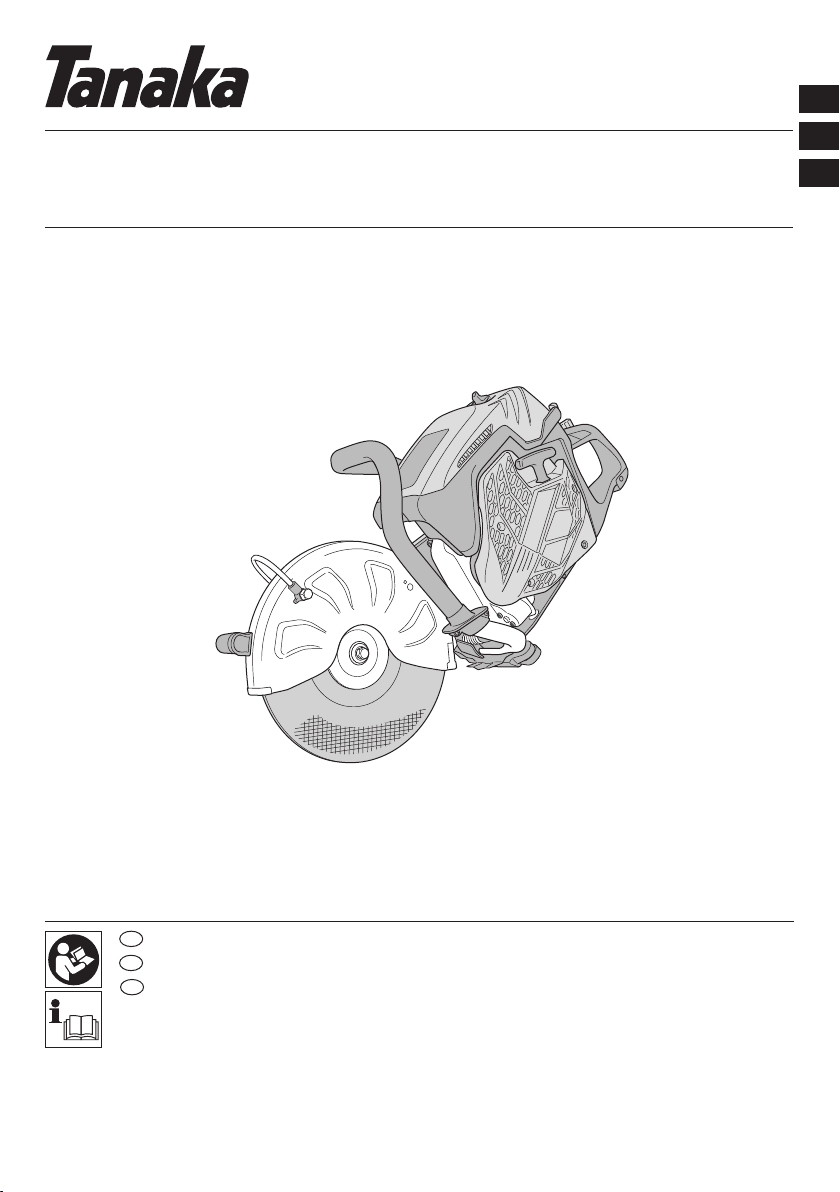
Tanaka TCM 75EAP User manual

TCM 75EAP・TCM 75EBP
Handling instructions
Instrucciones de manejo
Instruções de uso
en
es
pt
en
es
pt
000BookTCM75EAPSA.indb1000BookTCM75EAPSA.indb1 2018/02/1415:15:052018/02/1415:15:05

2
1
234
567
R
a
OGLK
F
H
Q
Y
Q
Z
V
AI
C
DB
bc
ef
d
J
S
Q
EW
XM
UT
N
1
2
3
5
4
3
6
P
000BookTCM75EAPSA.indb2000BookTCM75EAPSA.indb2 2018/02/1415:15:052018/02/1415:15:05

3
8910
11 12 13
14 15 16
17 18 19
2
3
7
8
4
11
12
12
13 11
14
15
16
14
17 18 19
6
4
9
10
6
000BookTCM75EAPSA.indb3000BookTCM75EAPSA.indb3 2018/02/1415:15:052018/02/1415:15:05

4
20 21 22
25-50 1
23 24 25
26 27 28
29 30
26
29
28
30
22 21
31
23
20
22
25
21
24
27
000BookTCM75EAPSA.indb4000BookTCM75EAPSA.indb4 2018/02/1415:15:062018/02/1415:15:06

5
31 32 33
34
35 36 37
32
33
34
38
37
35
36
6
40 40
40
4
41 42 43
44
45
0.6 mm
39
000BookTCM75EAPSA.indb5000BookTCM75EAPSA.indb5 2018/02/1415:15:062018/02/1415:15:06

6
38 39
10
11
0 mm
44
43
43
45
000BookTCM75EAPSA.indb6000BookTCM75EAPSA.indb6 2018/02/1415:15:062018/02/1415:15:06

English
7
Pay special attention to statements preceded by the
following words:
WARNING
Indicates a strong possibility of severe personal injury or
loss of life if instructions are not followed.
CAUTION
Indicates a possibility of personal injury or equipment
damage if instructions are not followed.
NOTE
Helpful information for correct function and use.
MEANINGS OF SYMBOLS
NOTE: Some units do not carry them.
Symbols
WARNING
The following show symbols used for the
machine. Be sure that you understand their
meaning before use.
Cutter: Portable cut-offmachine
TCM75EAP / TCM75EBP
It is important that you read, fully understand
and observe the following safety precautions
and warnings. Careless or improper use of
the unit may cause serious or fatal injury.
Read, understand and follow all warnings and
instructions in this manual and on the unit.
Always wear eye, head and ear protectors,
and also dust protection, when using this unit
Choke
On / Start
Off/ Stop
Emergency stop
Maximum spindle speed of the machine.
Warning: Do not use wheels that are rated for
speeds lower than the indicated maximum
spindle speed of the machine.
Fire warning! This tool generates sparks when
cutting metal.
Warning! Do not use damaged cut-offwheel.
Rotation direction of cut-offwheel
Cut-offwheel dimensions
Fuel and oil mixture
Carburetor adjustment - Idle speed
Carburetor adjustment - Low speed mixture
Carburetor adjustment - High speed mixture
Priming pump
8
Guaranteed sound power level
Decompression valve
Hazardous dust and gas emission warning
Kickback warning
Warning! Never use blades designed for
cutting wood.
WHAT IS WHAT? (Fig. 1)
A: Stop switch: Device for allowing the engine to be started
or stopped.
B: Throttle lever: Device activated by the operatorʼs finger,
for controlling the engine speed.
C: Throttle lever lockout: Device that prevents the
accidental operation of the throttle lever until manually
released.
D: Throttle lock: Device for setting the throttle in partially
open position to aid starting.
E: Fuel tank cap: For closing the fuel tank.
F: Starter knob: Pull handle to start the engine.
G: Front handle: Support handle located at or towards the
front of the engine housing.
H: Rear handle: Support handle located at or towards the
rear of the engine housing.
I: Choke lever: Device for enriching the fuel/air mixture in
the carburetor, to aid starting.
J: Priming pump: Device for supplying extra fuel, to aid
starting.
K: Cleaner box (B): Cover for pre-filter
L: Cleaner box (A): Cover for paper-filter and carburetor.
M: Clutch cover: Device between the engine and the cutting
equipment designed to prevent unintentional contact
with the transmission.
N: Arm cover: Device between the engine and the cutting
equipment designed to prevent unintentional contact
with the transmission.
O: Wheel guard: Cover which is intended to protect the
operator from wheel contact, and also directs debris
away from the operator.
P: Nut: Secures the wheel guard to engine.
000BookTCM75EAPSA.indb7000BookTCM75EAPSA.indb7 2018/02/1415:15:062018/02/1415:15:06

English
8
Q: Anti-vibration spring: Reduce the transmission of
vibrations to the operator’s hands.
R: Handle(W): Handle for rotating the wheel guard.
S: Decompression valve: Device for reducing the
compression pressure of engine to aid starting.
T: Tensioner bolt: Device to increase and release belt
tension.
U: Tension nut: Mark for indicating the state of tension of
the belt.
V: Cut-offwheel: Bonded abrasive with reinforced resinoid
wheel for cutting, with blotter.
W: Coupler: Device for attaching the hose
X: Valve: Device for adjusting water flow rate.
Y: Muffler: Reduces engine exhaust noise and directs the
exhaust gases.
Z: Wheel washer: Flange provided to clamp and drive the
cut-offwheel.
a: Bolt: Secures the cut-offwheel
b: Adapter collar: Spindle attachment for using arbor hole
25.4mm cut-offwheels.
c: Combi box spanner: Maintenance tool for removing or
installing a spark plug
d: Hex. wrench: Maintenance tool for removing cover and
tensioning the belt.
e: Protective glasses: Eye protection.
f: Handling instructions: Included with unit. Read before
operation and keep for future reference to learn proper,
safe techniques.
WARNINGS AND SAFETY
INSTRUCTIONS
Operator safety
○Always wear a proper face shield or protective glasses.
○Gloves should always be worn when operating this
machine and also when touching the cut-offwheel.
○When using this machine, always wear proper protective
attire such as jacket, trousers, helmet, boots with steel
toe-caps and non-slip soles, and eye, ear, leg protection
equipment whenever you use this machine.
Do not wear loose clothing, jewelry, short pants and/or
sandals, or go barefoot.
○Never let a child or inexperienced person operate the
machine.
A first-time operator should obtain practical instruction
before using the machine.
○When you wear hearing protection, pay attention to your
surroundings. Be aware of any bystanders who may be
signaling a problem.
○Cutting operations can expose you to respiratory
hazards such as silica and other harmful dust particles.
Please wear a protective mask when operating this
machine.
○Keep handles free of oil and fuel.
○Keep hands away from cutting equipment.
○Do not grab or hold the machine by the cutting
equipment.
○Do not smoke or allow smoking near fuel or the machine,
or while using the machine.
○When the unit is shut off, make sure the cutting
attachment has stopped before setting down the unit.
○When operation is prolonged, take a break periodically
so that you may avoid possible Hand-Arm Vibration
Syndrome (HAVS) which is caused by vibration.
○National regulation can restrict the use of machine.
And the operator must obey the local regulations of
working area.
WARNING
○The machine produces exhaust fumes, which include
hydrocarbons and benzene. When using this machine,
sufficient ventilation is needed, not only if used indoors
but also when working in trenches, hollows or other
confined locations. Breathing exhaust fumes can be
fatal.
○Do not operate this machine when you are tired, ill or
under the influence of alcohol, drugs or medication.
○Antivibration systems do not guarantee that you will not
sustain Hand-Arm Vibration Syndrome or carpal tunnel
syndrome.
Therefore, continual end regular users should monitor
closely the condition of their hands and fingers. If any
of the above symptoms appear, seek medical advice
immediately.
○Long or continuous exposure to high noise levels may
cause permanent hearing impairment. Always wear
approved hearing protection when operating a machine.
○If you are using any medical electric/electronic devices
such as a pacemaker, consult your physician as well as
the device manufacturer prior to operating any power
equipment.
Unit / machine safety
○Inspect the entire machine for any damage before each
use. Check for fuel leaks and make sure all fasteners are
in place and securely tightened.
○Keep others away when making carburetor adjustments.
○Use only accessories as recommended for this machine
by the manufacturer.
○Select and mount the correct cut-offwheel for the type of
work to be carried out.
○All items, other than the items listed in the operator’s/
owner’s manual, should be performed by Tanaka dealer.
(For example, if improper tools are used to remove the
flywheel or if an improper tool is used to hold the flywheel
in order to remove the clutch, structural damage to the
flywheel could occur and could subsequently cause the
flywheel to burst.)
WARNING
○Never modify the machine in any way. Do not use your
machine for any job except that for which it is intended.
○Never use wheels that are rated for speeds lower than
the maximum spindle speed indicated on the machine.
A wheel running faster than its rated speed can break
and fly apart.
○The arbor size of wheels and flanges must properly fit
the spindle of the machine.
Wheels and flanges with arbor holes that do not match
the mounting hardware of the machine will run off-
balance, vibrate excessively and may cause loss of
control.
○It is important to use only cut-offwheels designed for use
on hand-held cut-offmachines. It is dangerous to use a
cut-offwheel that is not intended for a hand-held cut-off
machine.
Fuel safety
○Mix and pour fuel outdoors and where there are no
sparks or flames.
○Use a container approved for fuel.
○Wipe offall fuel spills and allow any remaining fuel to
evaporate before starting engine.
○Move at least 3 m away from fueling site before starting
engine.
○Stop engine and let it cool for a few minutes before
opening fuel tank cap.
○Store the machine and fuel in area where fuel vapors
cannot reach sparks or open flames from water heaters,
electric motors or switches, furnaces, etc.
000BookTCM75EAPSA.indb8000BookTCM75EAPSA.indb8 2018/02/1415:15:072018/02/1415:15:07

English
9
WARNING
Fuel is highly flammable and its fumes should not be
inhaled. Be particularly careful when handling the
machine as the sparks produced when cutting metal can
easily ignite any fuel spillage.
Cutting safety
○Keep bystanders at a safe distance, away from the
work area. Anyone entering the work area must wear
personal protective equipment. Flying fragments from
the workpiece or the cut-offwheel may cause injury.
Children, other unauthorized persons and animals must
remain well away from the work area.
○Hold the machine firmly with the right hand on the rear
handle and the left hand on the front handle.
○Keep firm footing and balance. Do not over-reach.
○Keep all parts of your body away from the muffler and
cutting attachment when the engine is running.
○Make sure to check the work area for any hidden
hazards such as water or gas pipes, electrical cables
and flammable substances.
○Never place the machine on the ground when running.
○Always ensure that the engine is shut offand any cutting
attachments have completely stopped before clearing
debris from the cutting attachment.
○Always carry a first-aid kit when operating any power
equipment.
○The muffler gets very hot during and after use. This also
applies during idling.
Be aware of the fire hazard, especially when working
near flammable substances and/or vapours.
WARNING
○Exhaust gases from the engine are hot and may contain
sparks which can cause a fire.
Also, sparks are generated when cutting metal with this
machine.
Never use the machine where flammable substances
and gases are present.
○Sparks generated from cutting operations can cause
fires. Always have adequate fire extinguishing equipment
available.
○When relocating to a new work area, be sure to shut off
the machine and ensure that all cutting attachments are
stopped.
○Always ensure that the engine is shut offand any cutting
attachments have completely stopped before moving.
Gyroscopic forces occur when moving while the engine
is operating and the cut-offwheel is rotating. This may
cause you to lose control of the machine.
○Never cut materials that consist of asbestos.
○Never leave the engine running while unattended
(e.g. on the ground).
Kickback and related warnings
Kickback is a sudden reaction to a pinched or snagged
rotating wheel. Pinching or snagging causes sudden stalling
of the rotating wheel which in turn causes the machine to
be forced in the direction opposite of the wheel's rotation at
the point of the binding. For example, if an abrasive wheel is
snagged or pinched by the workpiece, the edge of the wheel
that is entering into the pinch point can dig into the surface of
the material causing the wheel to climb out or kick out. The
wheel may either jump toward or away from the operator,
depending on the direction of the wheel's movement at the
point of pinching. Abrasive wheels may also break under
these conditions.
Either of these reactions may cause you to lose control of the
machine which could result in serious personal injury.
Kickback is the result of cut-offmachine misuse and/or
incorrect operating procedures or conditions that can be
avoided by taking proper precautions as given below.
○Kickback occurs when the upper angle of the cut-off
wheel is used or touches an object when the cut-off
wheel is running. Pay special attention not to touch the
upper angle of the cut-offwheel to any object. (Fig. 2,
Fig. 3)
○Use special care when working corners, sharp edges
etc. Avoid bouncing and snagging the cut-offwheel.
Corners, sharp edges or bouncing have a tendency to
snag the rotating wheel and cause loss of control or
kickback. (Fig. 4)
○Do not use cut-offwheels other than those approved or
recommended by the manufacturer. Never use blades
designed for cutting wood. Failure to comply could result
in personal accidents or injury.
○Do not jam the wheel or apply excessive pressure. Do
not attempt to make an excessive depth of cut.
Overstressing the wheel increases the loading and
susceptibility to twisting or binding of the wheel in the cut
and the possibility of kickback or wheel breakage.
○If the wheel binds or a cut is interrupted for any reason,
stop the engine and hold the machine motionless until
the wheel comes to a complete stop. Never attempt
to remove the wheel from the cut while the wheel is in
motion otherwise kickback may occur. Investigate and
take corrective action to eliminate the cause of wheel
binding.
○Do not restart the cutting operation with the wheel in the
workpiece. After allowing the wheel to reach full speed,
carefully re-enter the cut. The wheel may bind, walk up or
kickback if the power tool is restarted in the workpiece.
○Provide supports for panels or any oversized workpiece
to minimize risk of wheel pinching and kickback.
Large workpieces tend to sag under their own weight.
Supports must be placed under the workpiece so that
the cutting surface to open. (Fig. 5)
Maintenance safety
○Maintain the machine according to recommended
procedures.
○Disconnect the spark plug before performing
maintenance except for carburetor adjustments.
○Keep others away when making carburetor adjustments.
○Use only genuine Tanaka replacement parts as
recommended by the manufacturer.
CAUTION
Do not disassemble the recoil starter. There is a
possibility of personal injury with recoil spring.
WARNING
Improper maintenance could result in serious engine
damage or in serious personal injury.
Transport and storage
○Carry the machine by hand with the engine stopped and
the muffler away from your body.
○Allow the engine to cool, empty the fuel tank and
carburetor, and secure the machine before storing or
transporting.
○Store machine out of the reach of children.
○Clean and maintain the machine carefully and store it in
a dry place.
○Make sure stop switch is offwhen transporting or storing.
○Do not store the cut-offwheels in a wet or frost condition.
Pay special attention about the abrasive wheel.
There is a risk of bursting to using the abrasive wheel
wetted.
If situations occur which are not covered in this manual, take
care and use common sense. Contact Tanaka dealer if you
need assistance.
000BookTCM75EAPSA.indb9000BookTCM75EAPSA.indb9 2018/02/1415:15:072018/02/1415:15:07

English
10
SPECIFICATIONS
Model TCM75EAP TCM75EBP
Engine displacement (cm3) 75.0
Spark Plug NGK BPMR-7A
Max. engine power by ISO 7293 (kW) 3.9
Rated engine speed by ISO 7293 (min-1) 9200
Max. engine speed (min-1) 9800
Idle engine speed (min-1) 2500
Fuel Tank Capacity (L) 1.1
Dry weight (kg)
Without fuel, wheel and accessories 10.4 10.6
Abrasive wheel
Wheel type Type 41
Outer diameter (mm) 305 (12") 355 (14")
Arbor hole diameter (mm) 20 (25.4 with Adapter collar)
Max. speed (min-1) 5100 or more
Max. Thickness (mm) 3.5 4.0
Diamond wheel
Outer diameter (mm) 305 (12") 355 (14")
Arbor hole diameter (mm) 20 (25.4 with Adapter collar)
Max. speed (min-1) 5100 or more
Max. Thickness (mm) 3.5 4.0
Minimum flange outside diameter (mm) 101.7
Wheel-fastener tightening torque (N·m) 20
Spindle diameter (mm) 20 (25.4 with Adapter collar)
Spindle max. speed (min-1) 4200
Sound pressure level LpA*1(dB(A)) by ISO 19432
Measured / Uncertainty 99.5 / 3.0
Sound power level LwA*2 (dB(A)) by ISO 19432
Measured / Uncertainty 115 / 3.0
Vibration level (m/s2) by ISO 19432
Front handle*1 / Rear handle*1
Uncertainty 2.2 / 2.7
1.0 2.4 / 2.9
1.0
NOTE
Noise level/vibration levels are calculated as the time-
weighted energy total for noise / vibration levels under
various working conditions with the following time
distribution:
*1:1/7 idle, 6/7 full load.
*2: Full load.
All data subject to change without notice.
ASSEMBLY PROCEDURES
Assembly of cut-offwheel
1. Place the wheel (1) between the two flanges (2), and
tighten the bolt (3) by hand. (Fig. 6)
2.
Insert the hex. wrench (4) into the hole of arm cover (5)
and lock the spindle in place while tightening the bolt (3)
securely using the combi box spanner (6). (Fig. 7)
3. Make sure the rotation direction of the diamond wheel
conforms to the direction indicated on the clutch cover
and install the diamond wheel. (Fig. 8)
NOTE
○
When using a wheel with an arbor hole of 25.4mm, securely
attach the adapter collar (7) to the spindle. (Fig. 9)
○Select and mount the correct cut-offwheel for the type of
work to be carried out.
Abrasive wheels Diamond wheels
Plastic (Special wheel) —
Masonry
Metal (Special wheels)
Cast iron (Special wheels)
WARNING
○Do not use damaged wheels. Before each use, inspect
the wheels for chips, cracks, distortion of shape or
imbalance and reject any such wheel.
○When you use the abrasive cut-offwheel check the
expiration year marked (8) on the wheel before attaching.
(Fig. 10)
There is a risk of bursting when using a wheel that it past
its expiration year.
○Before tightening the bolt, check that the direction of the
two flanges is correct. Also check that the flanges are
securely installed in the flats of the spindle.
○The correct tightening torque is 20 N·m. Do not tighten
more than 20 N·m.
○Check the wheel by running it for 1 minutes at full throttle
before applying it to a workpiece.
000BookTCM75EAPSA.indb10000BookTCM75EAPSA.indb10 2018/02/1415:15:072018/02/1415:15:07

English
11
Adjustment of belt
1. Loosen the nut (9) with the combi box spanner (6) so that
the arm cover can (10) move. (Fig. 11)
2. Use the hex. wrench (4) to rotate the tensioner bolt (11)
so that the position of the tension nut (12) matches with
the marking (13) on the arm cover (10). (Fig. 12, Fig. 13)
3. Tighten the nut again.
NOTE
Sufficient power is not transmitted to the wheel when the
belt is loose. Appropriately adjust the belt as necessary.
Adjustment of wheel guard
1. Wheel guard (14) can be moved by hand without using
a tool. To adjust the wheel guard (14), use handle(W)
(15), or press the end of wheel guard (14) against the
workpiece. (Fig. 14)
Make sure to adjust the wheel guard (14) to shield you
from any flying debris. (Fig. 15)
Wet cutting with water
This machine can be set up for wet cutting which can
suppress dust emission during cutting.
1. Remove coupler (16) by pulling the coupler from the
machine. (Fig. 16)
2. Remove the ring (17) from the coupler, slide the ring over
the hose and insert the hose to the coupler. (Fig. 17)
3. Re-tighten the ring to the coupler securely.
4. Reattach the coupler to the machine until it locks into
position.
5. Running water into the hose, turn the lever (18) of valve
(19). (Fig. 18) This will supply to the cut-offwheel.
Warning
The cut-offwheel that is included with this machine is an
abrasive cut-offwheel for concrete, stone, or masonry.
When cutting with water supplied to this cut-offwheel,
use the wheel up on the same day. There is a risk of
bursting when using the abrasive wheel wetted in this
manner on the following day.
For other cut-offwheels, follow the instructions provided
with those cut-offwheels.
Mounting the tools to the machine (Fig. 19)
This machine is designed to store the combi box spanner (6)
and hex. wrench (4).
OPERATING PROCEDURES
Fuel
WARNING
○The machine is equipped with a two-stroke engine.
Always run the engine on fuel, which is mixed with oil.
Provide good ventilation, when fueling or handling fuel.
○Fuel is highly flammable and it is possible to get seriously
injured when inhaling or spilling on your body.
Always pay attention when handling fuel. Always have
good ventilation when handling fuel.
Fuel (Fig. 20)
○Always use branded 89 octane unleaded gasoline.
○Use genuine two-cycle oil or use a mix between 25:1 to
50:1, please consult about the oil mixture ratio to Tanaka
dealer.
○If genuine oil is not available, use an anti-oxidant added
quality oil expressly labeled for air-cooled 2-cycle engine
use (JASO FC GRADE OIL or ISO EGC GRADE). Do not
use BIA or TCW (2-stroke water-cooling type) mixed oil.
○Never use multi-grade oil (10 W/30) or waste oil.
○Never mix fuel and oil in machine’s fuel tank. Always mix
fuel and oil in a separate clean container.
Fuel mixing method
Always start by filling half the amount of gasoline, which is to
be used into container.
Then add the whole amount of oil. Mix (shake) the fuel
mixture. Add the remaining amount of gasoline.
Mix (shake) the fuel-mix thoroughly before filling the fuel tank.
Mixing amount of two-cycle oil and gasoline
Gasoline (Liter) Two-cycle oil (ml)
Ratio 50:1 Ratio 25:1
0.5 10 ——— 20
1 20 ——— 40
2 40 ——— 80
4 80 ——— 160
Fueling (Fig. 21)
Before fueling, clean fuel tank cap (20) area carefully to
ensure that no dirt falls into the tank. Make sure that the fuel
is well mixed by shaking the container before adding fuel.
WARNING
○Always shut offthe engine and let it cool for a few
minutes before refueling.
Do not smoke or bring flames or sparks near the fuel.
○Slowly open the fuel tank cap (20), when filling up with
fuel, so that possible overpressure disappears.
○Tighten the fuel tank cap carefully, after fueling.
○Always move the unit at least 3 m from the fueling area
before starting.
○Always wash any spilled fuel from clothing immediately
with soap.
○Be sure to check any fuel leaking after refueling.
○Before fueling, in order to remove static electricity from
the main body, the fuel container and the operator,
please touch the ground that is slightly damp.
Starting the cold engine (Fig. 22-27)
CAUTION
Before starting, make sure that the cut-offwheel does
not touch anything.
1. Set stop switch (21) to ON position. (Fig. 22)
2. Pull choke lever (22) fully to set it in the START position.
(Fig. 23)
3. Push the priming pump (23) approximately ten times so
that fuel flows into carburetor. (Fig. 24)
4. Fully pull the throttle lever (24) while pressing the throttle
lever lockout (25). Then press the throttle lock (27).
This will automatically lock to half throttle, to aid in
starting the engine. (Fig. 22)
5. Push the decompression valve (26). The valve will
automatically return to the original position once the
engine has started. (Fig. 25)
6. Holding the tool in position with the left hand on the front
handle (29) and the right foot pressing down on the rear
handle (30), rapidly pull the starter knob (28). (Fig. 26)
7. When you hear first ignition, push the choke lever (22)
fully to set it in the run position. (Fig. 27)
8. Push decompression valve (26) again.
9. Pull starter knob (28) rapidly again in the aforementioned
manner.
10. As soon as the engine starts, pull throttle lever (24)
full once with throttle lever lockout (25) pressed and
immediately release throttle lock (27). Then half throttle
is disengaged.
11. Allow the engine to warm up for about 2 to 3 minutes
before cutting.
NOTE
To avoid reducing engine life, do not run the engine at
high speeds without any load over a long period of time.
Starting the warm engine
Use only 1, 5, and 6 of the starting procedure for a cold
engine.
If the engine does not start, use the same starting procedure
as for a cold engine.
000BookTCM75EAPSA.indb11000BookTCM75EAPSA.indb11 2018/02/1415:15:082018/02/1415:15:08

English
12
Stopping (Fig. 28)
Decrease engine speed, and push stop switch (21) to stop
position.
WARNING
Do not put the machine where there are flammable
materials such as dried grass, since the muffler is still
hot after the engine has stopped.
Basic cutting techniques
1. Adjust the wheel guard to shield you from flying debris.
2. Cut a straight shallow line (31) to the range to be cut.
(
Fig. 29
)
3. Cut straight along the line to the required depth.
WARNING
○Do not overreach or cut above shoulder height.
○
Operator and bystanders must not stand in the line of
rotation of the cut-offwheel. Doing so may result in serious
injury or death should the wheel burst.
○
Never apply lateral pressure (side force) to the cut-off
wheel during cutting. Doing so will damage the cut-off
wheel.
○
Do not cut in a curved line.
NOTE
○When cutting, move the machine back and forward along
the line in order to be not overheat the cut-offwheel.
If you cut the same position in long time, the cut-offwheel
may get hot and be weakened.
○Always cut at full speed at all times with pressing lightly.
This is the way to get best efficient for cutting.
○Do not cut a deep groove at one time. To make deep
groove, cut several times a shallow groove.
MAINTENANCE
Carburetor adjustment
In the carburetor, fuel is mixed with air. When the engine is
test run at the factory, the carburetor is adjusted. A further
adjustment may be required, according to climate and
altitude. The carburetor has one adjustment possibility:
T = Idle speed adjustment screw.
Idle speed adjustment (T) (Fig. 30)
Check that the pre-filter and paper filter are clean. When the
idle speed is correct, the cutting attachment will not rotate.
If adjustment is required, close (clockwise) the T-screw, with
the engine running, until the cutting attachment starts to
rotate. Open (counter-clockwise) the screw until the cutting
attachment stops. You have reached the correct idle speed
when the engine runs smoothly in all positions well below the
rpm when the cutting attachment starts to rotate.
If the cutting attachment still rotates after idle speed
adjustment, contact Tanaka dealer.
WARNING
When the engine is idling, the cutting attachment must
not rotate under any circumstances.
NOTE
○Please use combi box spanner for adjusting the T-screw.
○Do not touch the High speed adjustment (H) and the Low
speed adjustment (L) screws on the carburetor. Those
are only for Tanaka dealer. If you rotate them, it will
cause a serious damage to the machine.
Air filter (Fig. 31)
If the engine power seems to have decreased, it is likely
because the air filter needs to be cleaned.
1. Before cleaning the air filter, pull the choke lever (22) to
prevent dust from entering into the engine.
2. Open cleaner box (B) (32) by loosening cleaner knob
(33) to expose the pre-filter (sponge form) (34) inside the
cleaner box (B) (32).
3. Clean the pre-filter by tapping or blowing it gently. If the
pre-filter is still dirty, rinse it in warm soap suds.
If the inside of cleaner box (B) (32) that is closed offby the
pre-filter is dirty with dust, clean the paper-filter (35) in the
following manner.
4. In order to take out of paper-filter (35) and nylon-filter
(36), open the cleaner box (A) (37) by loosening the M5
set bolt (38).
5. Clean the nylon-filter by tapping or blowing it gently. If
the nylon-filter is still dirty, rinse it in warm soap suds.
6. Clean the paper-filter by tapping. If you use compressed
air to blow out the dust, apply the air gently from inside.
7. Reassemble the parts to their original positions by
following the aforementioned steps in reverse.
NOTE
○When you remove paper-filter and nylon-filter, please
take care so that dust does not get inside the engine.
○After rinsing in warm soap suds. Check to make sure that
the filter is dry before reassembly. An air filter that has
been used for some time cannot be cleaned completely.
Therefore, it must regularly be replaced with a new one.
A damaged filter must always be replaced.
Spark plug (Fig. 31, 32, 33)
1. Remove cleaner box (B) (32) and cleaner box (A) (37).
(Fig. 31)
2. Remove the spark plug by turning it counterclockwise
with the combi box spanner. (Fig. 32)
3. Clean the spark plug if it is dirty. Check the electrode
gap. The correct gap is 0.6 mm. (Fig. 33)
NOTE
○When you remove the spark plug, please take care so
that dust does not get inside the engine.
○The spark plug should be replaced after about 100
operation hours or earlier if the electrodes are badly
eroded.
Fuel filter (Fig. 34)
Remove the fuel filter (39) from the fuel tank and thoroughly
wash it in solvent. After that, push the fuel fi
lter into the tank
completely.
NOTE
If the fuel filter (39) is hard due to dust and dirt, it must be
replaced.
Anti-vibration systems (Fig. 35)
Check the springs (40) for any loosening or damage. If you
find any failure in those parts, please contact a Tanaka
dealer.
Replacing of belt
1. Remove nut (9) using the combi box spanner (6)
and loosen the tensioner bolt (11) by rotating it
counterclockwise with the hex. wrench (4). Then,
remove the arm cover (10). (Fig. 11, 12)
2. Loosen the three bolts (41) on the clutch cover (42) and
remove clutch cover (42). (Fig. 36)
3. Remove the belt (43) and set a new one in the grooves of
the pulleys (44)(45) securely. (Fig. 37, 38)
4. Before assembling, turn the tensioner bolt (11) and
adjust the length protrusion of the tensioner bolt (11)
from the arm cover (10) to 0 mm. (Fig. 39)
5. Assemble clutch cover and arm cover by following the
aforementioned steps in reverse.
6. Readjust the tension of the belt. Please refer to
“Adjustment of belt”.
000BookTCM75EAPSA.indb12000BookTCM75EAPSA.indb12 2018/02/1415:15:082018/02/1415:15:08

English
13
Maintenance schedule
Daily maintenance
○Clean the exterior of the machine.
○
Check that the nut on the arm cover is sufficiently tightened.
○
Check that the bolts for the cut-offwheel are sufficiently
tightened.
○
Check that the cut-offwheel does not rotate when the
engine is idling
○Clean the air filter.
Weekly maintenance
○Check the recoil starter, especially rope.
○Clean the exterior of the spark plug.
○Remove the spark plug and check the electrode gap.
Adjust it to 0.6 mm or change the spark plug.
○
Check that the air intake at the recoil starter is not clogged.
TROUBLESHOOTING
Condition Probable Cause Remedy
Engine does not start
No fuel or low fuel Supply fuel
Fuel is not in the carburetor Supply fuel and push priming pump a
few times.
Old fuel Supply new fuel
Spark plug is wet 1. Remove spark plug and dry it
2. Pull starter and dry the fuel inside
the engine
The fuel pipe is bent or detached Consult a Tanaka dealer
Carburetor failure Consult a Tanaka dealer
Spark plug failure Replace spark plug or correct the gap
Electrical system failure Consult a Tanaka dealer
Engine starts but immediately stalls
No fuel or low fuel Supply fuel
Fuel is not in the carburetor Supply fuel and push priming pump a
few times.
The choke is closed Push choke lever securely
Carburetor failure Consult a Tanaka dealer
Spark plug failure Replace spark plug or correct the gap
Clogged air filter Clean the air filter
Abnormal vibration
Faulty mounting of the cut-offwheel Please refer to “Assembly of cut-off
wheel”
Deformation of the cut-offwheel Replace the cut-offwheel
Anti-vibration system failure Consult a Tanaka dealer
Engine starts, but the cut-offwheel
does not rotate
Belt is loose Please refer to “Adjustment of belt”
Belt is too tight
Belt is out of pulleys Please refer to “Replacing of belt”
Engine does not stop Electrical system failure Consult a Tanaka dealer
REPLACEMENT PARTS
6699872 6699868 6699867 6699877
Monthly maintenance
○Rinse the fuel tank with gasoline, and clean fuel filter.
○Clean the exterior of the carburetor and the space
around it.
Quarterly maintenance
○Clean the cooling fins on the cylinder.
○Clean the fan and the space around it.
○Clean the carbon of muffler.
CAUTION
Cleaning of cylinder fins, fan and muffler shall be done
by Tanaka dealer.
000BookTCM75EAPSA.indb13000BookTCM75EAPSA.indb13 2018/02/1415:15:082018/02/1415:15:08

Español
14
Dedique especial atención a los apartados introducidos por
las siguientes palabras:
ADVERTENCIA
Indica un riesgo significativo de que se produzcan daños
personales graves e incluso la muerte si no se siguen las
instrucciones.
PRECAUCIÓN
Indica la posibilidad de que se produzcan daños
personales o materiales si no se siguen las instrucciones.
NOTA
Indica información útil para el uso y funcionamiento
correctos de la máquina.
SIGNIFICADO DE LOS SÍMBOLOS
NOTA: Algunas unidades no están provistos de ellos.
Símbolos
ADVERTENCIA
A continuación se muestran los símbolos
utilizados para la máquina. Asegúrese de
comprender su significado antes de utilizar el
dispositivo.
Cuchilla: Máquina de corte portátil
TCM75EAP / TCM75EBP
Es importante que lea, entienda totalmente
y respete las siguientes precauciones
y advertencias de seguridad. El uso
descuidado o incorrecto de la unidad podría
provocarle lesiones graves o fatales.
Lea, comprenda y siga todas las advertencias
y demás instrucciones de este manual y las
que se muestran en el aparato.
Cuando utilice esta unidad, use siempre
protecciones para los ojos, la cabeza, los
oídos y protecciones antipolvo
Estárter
Encendido / Arranque
Apagado / Parada
Parada de emergencia
Velocidad máxima del husillo de la máquina.
Advertencia: No utilice discos con una
capacidad de velocidad inferior a la velocidad
máxima indicada del husillo de la máquina.
¡Advertencia de incendios! Esta herramienta
genera chispas al cortar metal.
¡Advertencia! No utilice discos de corte
dañados.
Dirección de giro del disco de corte
Dimensiones del disco de corte
Mezcla de combustible y aceite
Ajuste del carburador: velocidad a ralentí
Ajuste del carburador: mezcla a baja velocidad
Ajuste del carburador: mezcla a alta velocidad
Bomba de cebado
8
Nivel de potencia acústica garantizado
Válvula de descompresión
Advertencia de polvo y emisiones de gas
dañinos
¡Advertencia de retroceso
¡Advertencia! Nunca utilice cuchillas
diseñadas para cortar madera.
DESCRIPCIÓN DE LAS PARTES (Fig. 1)
A: Interruptor de parada: Dispositivo que permite arrancar y
detener el motor.
B: Palanca del acelerador: Dispositivo activado mediante el
dedo del operario para controlar la velocidad del motor.
C: Bloqueo de la palanca del acelerador: Dispositivo que
evita el funcionamiento accidental de la palanca del
acelerador hasta que se libera manualmente.
D: Bloqueo del acelerador: Dispositivo de configuración
del acelerador en la posición parcialmente abierta para
ayudar al arranque.
E: Tapa del depósito de combustible: Para cerrar el
depósito de combustible.
F: Mando del arrancador: Tire del asidero para arrancar el
motor.
G: Asidero frontal: Asidero de apoyo situado en la parte
frontal de la carcasa del motor u orientado hacia ella.
H: Asidero trasero: Asidero de apoyo situado en la parte
trasera de la carcasa del motor u orientado hacia ella.
I: Palanca del estárter: Dispositivo para enriquecer la
mezcla de combustible/aire, para ayudar al arranque.
J: Bomba de cebado: Dispositivo para suministrar
combustible adicional para ayudar al arranque.
K: Caja del filtro (B): Cubierta del prefiltro
L: Caja del filtro (A): Cubierta del filtro de papel y del
carburador.
M: Tapa del embrague: Dispositivo entre el motor y el
equipo de corte diseñado para evitar el contacto no
intencionado con la transmisión.
000BookTCM75EAPSA.indb14000BookTCM75EAPSA.indb14 2018/02/1415:15:082018/02/1415:15:08

Español
15
N: Cubierta del brazo: Dispositivo entre el motor y el
equipo de corte diseñado para evitar el contacto no
intencionado con la transmisión.
O: Protección del disco: Cubierta diseñada para proteger al
operario del contacto del disco y para alejar los residuos
del operario.
P: Tuerca: Fija la protección del disco al motor.
Q: Resorte antivibración: Reduce la transmisión de
vibraciones a las manos del operario.
R: Asidero (W): Asidero para girar la protección del disco.
S:
Válvula de descompresión: Dispositivo para reducir la
presión de compresión del motor para ayudar al arranque.
T: Perno tensor: Dispositivo para aumentar y liberar tensión
de la correa.
U: Tuerca de tensión: Marca para indicar el estado de la
tensión de la correa.
V: Disco de corte: Disco abrasivo adherido con resina
sintética reforzada para el corte con papel secante.
W: Acoplador: Dispositivo para instalar la manguera
X: Válvula: Dispositivo para ajustar la tasa del flujo de agua.
Y: Silenciador: Reduce el ruido de salida de escape del
motor y dirige los gases de escape.
Z: Arandela del disco: Brida suministrada para fijar y dirigir
el disco de corte.
a: Perno: Fija el disco de corte
b: Anillo adaptador: Accesorio del husillo para el uso de
discos de corte de 25,4 mm de orificio de eje.
c:
Llave combinada de cubo: Herramienta de mantenimiento
para extraer o instalar una bujía
d: Llave hexagonal: Herramienta de mantenimiento para
extraer cubiertas y tensar la correa.
e: Gafas protectoras: Protección para los ojos.
f: Instrucciones de manejo:Incluidas con la unidad.Lea las
instrucciones para aprender a utilizar apropiadamente
y con seguridad la unidad, y guárdelas para futuras
referencias.
ADVERTENCIAS E INSTRUCCIONES
DE SEGURIDAD
Seguridad del usuario
○ Use siempre protección facial o gafas protectoras
adecuadas.
○ Al operar esta máquina y tocar el disco de corte, debe
usar siempre guantes.
○ Utilice siempre indumentaria protectora adecuada tal
como chaqueta, pantalones, casco, botas con puntera
de acero y suelas antideslizantes, así como equipo de
protección ocular, auditivo y para las piernas, cuando
utilice esta máquina.
No utilice prendas sueltas, joyas, pantalones cortos y/o
sandalias, y nunca trabaje descalzo.
○No deje que niños o personas inexpertas utilicen esta
máquina.
El operario primerizo deberá obtener instrucciones
prácticas antes de usar la máquina.
○ Cuando use protección auditiva, preste atención a los
alrededores. Esté atento a personas que pudieran estar
avisándole de un problema.
○ Las operaciones de corte pueden exponerlo a peligros
respiratorios tales como sílice y otras partículas de
polvo perjudiciales. Al utilizar esta máquina, utilice una
máscara protectora.
○Mantenga los asideros libres de aceite y combustible.
○Mantenga las manos alejadas del mecanismo de corte.
○No agarre ni sostenga la máquina por el mecanismo de
corte.
○ No fume ni deje fumar a otras personas en las
proximidades del combustible o de la máquina ni cuando
utilice la misma.
○ Cuando apague la unidad, asegúrese de que el
mecanismo de corte se ha detenido antes de apoyar la
unidad sobre el suelo.
○Si utiliza este dispositivo durante un periodo de tiempo
prolongado, se recomienda descansar de vez en cuando
para evitar el posible Síndrome por vibración en manos y
brazos (HAVS), causado por las vibraciones.
○Las normativas nacionales pueden restringir el uso de la
máquina.
El operario deberá respetar los reglamentos locales del
área de trabajo.
ADVERTENCIA
○La máquina genera gases de escape, que incluyen
hidrocarburos y benceno. Al utilizar esta máquina,
necesitará la ventilación adecuada no solamente al
usarse en interiores, sino también al usarse en zanjas,
cavidades y otras ubicaciones confinadas. La inhalación
de los humos de escape puede ser fatal.
○No utilice esta máquina cuando esté cansado, enfermo o
bajo la influencia del alcohol, drogas o medicamentos.
○Los sistemas antivibración no garantizan que no se
vaya a padecer del Síndrome por vibración en manos y
brazos o el síndrome del túnel carpiano.
Por lo tanto, aquellas personas que utilicen este dispositivo
de forma continua y regular deberán mantener vigilado en
todo momento el estado de sus manos y dedos.Si aparece
cualquiera de los síntomas citados, deberá solicitarse
inmediatamente atención médica.
○La exposición prolongada o continua a niveles altos de
ruido puede causar discapacidad auditiva permanente.
Al utilizar una máquina que genere ruidos, utilice
siempre protección auditiva aprobada.
○Si utiliza algún dispositivo médico eléctrico o electrónico
tal como marcapasos, consulte a su médico y al
fabricante del dispositivo antes de utilizar cualquier
equipo motorizado.
Seguridad de la máquina
○Inspeccione toda la máquina en busca de daños
antes de cada uso. Compruebe que no haya fugas de
combustible y asegúrese de que todas las piezas se
encuentren en su sitio y estén correctamente apretadas.
○No permita que se acerquen otras personas mientras
esté ajustando el carburador.
○Utilice únicamente los accesorios para esta máquina
que hayan sido recomendados por el fabricante.
○Seleccione y monte el disco de corte correcto para el
tipo de trabajo que se vaya a llevar a cabo.
○Todos los elementos que no sean los elementos que se
indican en el manual del operario/propietario, deben ser
llevados a cabo por un distribuidor Tanaka. (Por ejemplo,
si se emplean herramientas incorrectas para quitar el
volante o si se utiliza una herramienta incorrecta para
sujetar el volante con el propósito de quitar el embrague,
podría ocasionar daños estructurales al volante y
provocar que se rompa).
ADVERTENCIA
○Nunca intente modificar la máquina de ninguna manera.
No utilice esta máquina para tareas distintas para las
que ha sido diseñada.
○Nunca utilice discos con una capacidad de velocidad
inferior a la velocidad máxima indicada del husillo de la
máquina.
Un disco funcionando más rápido que su velocidad
nominal puede romperse y saltar en pedazos.
○El diámetro del eje de los discos y bridas ha de encajar
correctamente en el husillo de la máquina.
Los discos y bridas que posean diámetros de eje que
no coincidan con el hardware de montaje de la máquina
se desequilibrarán, vibrarán excesivamente y podrían
causar una pérdida del control.
000BookTCM75EAPSA.indb15000BookTCM75EAPSA.indb15 2018/02/1415:15:092018/02/1415:15:09

Español
16
○Es importante utilizar únicamente discos de corte
diseñados para su uso en máquinas de corte portátiles.
Es peligroso utilizar un disco de corte no diseñado para
una máquina de corte portátil.
Seguridad del combustible
○Mezcle y llene el combustible al aire libre, en lugares
donde no se produzcan chispas ni haya fuego.
○Utilice un recipiente adecuado para el combustible.
○Limpie los derrames de combustible y permita que
cualquier combustible restante se evapore antes de
arrancar el motor.
○Antes de poner en marcha el motor, apártese como
mínimo 3 metros del lugar en el que se ha repostado el
combustible.
○Detenga el motor y deje que se enfríe durante unos
minutos antes de abrir el tapón del depósito de
combustible.
○Guarde la máquina y el combustible en un lugar donde
los vapores del combustible no puedan llegar a chispas
ni llamas de calentadores de agua, motores eléctricos,
interruptores, hornos, etc.
ADVERTENCIA
El combustible es altamente inflamable y sus vapores
no deben ser inhalados. Tenga especial cuidado al
manipular la máquina, ya que las chispas producidas
durante el proceso de corte de metal pueden inflamar
fácilmente cualquier derrame de combustible.
Seguridad durante el corte
○Mantenga a los viandantes a una distancia segura del
área de trabajo. Cualquier persona que acceda a la zona
de trabajo deberá usar equipo protector personal. Los
fragmentos despedidos de las piezas de trabajo o del
disco de corte podrían causar lesiones.
Los niños, el resto de personal no autorizado y los
animales deberán permanecer alejados de la zona de
trabajo.
○Agarre la máquina firmemente con la mano derecha
en el asidero trasero y la mano izquierda en el asidero
delantero.
○Mantenga estable el cuerpo, con los pies bien apoyados
sobre el suelo. No estire demasiado el cuerpo.
○Mantenga su cuerpo apartado del silenciador de escape
y del mecanismo de corte mientras esté en marcha el
motor.
○Asegúrese de comprobar la zona de trabajo en busca
de peligros ocultos tales como tuberías de agua o gas,
cables eléctricos y sustancias inflamables.
○Jamás coloque la máquina sobre el suelo cuando esté
en marcha.
○Asegúrese siempre de que el motor esté apagado y de
que todos los accesorios de corte estén completamente
parados antes de limpiar los residuos del accesorio de
corte.
○Cuando utilice cualquier equipo motorizado, lleve
siempre un botiquín de primeros auxilios consigo.
○El silenciador alcanza temperaturas muy elevadas
durante y después de su uso. Esta situación también se
da durante su inactividad.
Tenga presente el riesgo de incendio, especialmente al
trabajar cerca de sustancias o vapores inflamables.
ADVERTENCIA
○Los gases de escape del motor alcanzan temperaturas
muy elevadas y podrían contener chispas que podrían
provocar un incendio.
Además, al cortar metal con esta máquina se generan
chispas.
No utilice nunca la máquina en lugares en los que
existan substancias y gases inflamables.
○Las chispas generadas por las operaciones de corte
podrían causar incendios. Tenga disponible en todo
momento un equipo de extinción de incendios adecuado.
○Cuando cambie para situarse en una nueva área de
trabajo, asegúrese de detener la máquina y de que
todos los accesorios de corte estén detenidos.
○Asegúrese siempre de que el motor esté apagado y de
que todos los accesorios de corte estén completamente
parados antes de desplazarse.
Durante el transporte del motor mientras éste está
funcionando y el disco de corte está girando se producen
fuerzas giroscópicas. Esto podría provocar la pérdida de
control de la máquina.
○Nunca corte materiales con amianto.
○Nunca deje el motor en marcha desatendido
(por ejemplo, sobre el suelo).
Retroceso y advertencias relacionadas
Retroceso es una reacción repentina en un disco giratorio
enganchado o atrapado. El enganche o agarre causa el
estancamiento repentino del disco giratorio, el cual a su
vez, causa que la máquina salga disparada en dirección
opuesta al giro del disco en el punto de unión. Por ejemplo,
si un disco abrasivo queda atrapado o atascado a causa
de una pieza de trabajo, el borde del disco que pasa por el
punto de agarre puede penetrar en la superficie del material,
causando que el disco se monte o retroceda.El disco podría
entonces salir disparado hacia el operario o alejarse del
mismo, en función de la dirección del movimiento del disco
en el momento del atasco. Los discos abrasivos podrían,
igualmente, romperse en estas condiciones.
Cualquiera de estas reacciones podría hacer perder el
control de la máquina, pudiendo causar serias lesiones
personales.
Retroceso es el resultado un uso incorrecto de la máquina
de corte y/o los procedimientos de operación o condiciones
incorrectos que puede evitarse tomando las precauciones
necesarias, tal y como se indica a continuación.
○El retroceso se produce cuando el ángulo superior del
disco de corte se usa o toca un objeto cuando el disco
de corte está en marcha. Preste especial atención para
no tocar el ángulo superior del disco de corte con ningún
objeto. (Fig. 2, Fig. 3)
○Preste especial atención al trabajar en esquinas, bordes
afilados, etc. Evite que el disco de corte rebote o se
quede atrapado.
Las esquinas, los bordes afilados o el rebote tienden
a causar atascos en el disco giratorio y la pérdida de
control o el retroceso del mismo. (Fig. 4)
○No utilice discos de corte distintos a los aprobados o
recomendados por el fabricante. Nunca utilice cuchillas
diseñadas para cortar madera. De lo contrario podría
causar accidentes personales o lesiones.
○No atasque el disco ni aplique una presión excesiva. No
intente lograr una profundidad de corte excesiva.
Sobrecargar el disco aumenta la carga y la
susceptibilidad a giros o adhesiones del disco en el
corte, y la posibilidad de retroceso o rotura del disco.
○Sieldiscoseatasca oseinterrumpeuncorteporcualquier
motivo, detenga el motor y mantenga la máquina inerte
hasta que el disco se detenga completamente. Nunca
intente extraer el disco del corte mientras el disco
está en movimiento, de lo contrario podría retroceder.
Averigüe el motivo y tome la acción correctiva necesaria
para eliminar la causa del atascamiento del disco.
○No reinicie la operación de corte con el disco en la pieza
de trabajo. Una vez que el disco alcance la velocidad
máxima, vuelva a introducirlo en el corte con cuidado.
El disco podría atascarse, levantarse o retroceder si la
herramienta de alimentación es reiniciada en la pieza de
trabajo.
○Proporcione soportes para paneles o cualquier pieza de
trabajo de gran tamaño para reducir el riesgo de que el
disco se atasque o retroceda.
000BookTCM75EAPSA.indb16000BookTCM75EAPSA.indb16 2018/02/1415:15:092018/02/1415:15:09

Español
17
Las piezas de trabajo grandes tienden a deslizarse por
su propio peso.Los soportes deben colocarse debajo de
la pieza de trabajo de forma que la superficie de corte se
abra. (Fig. 5)
Seguridad durante el mantenimiento
○Realice el mantenimiento de la máquina siguiendo los
procedimientos recomendados.
○Antes de iniciar el mantenimiento, desconecte la bujía,
excepto si hay que ajustar el carburador.
○No permita que se acerquen otras personas mientras
esté ajustando el carburador.
○Utilice únicamente repuestos y accesorios originales de
Tanaka recomendados por el fabricante.
PRECAUCIÓN
No desmonte el arrancador de retroceso. El resorte
del arrancador puede ocasionarle lesiones personales
graves.
ADVERTENCIA
El mantenimiento incorrecto podría conducir a una
avería seria del motor o a heridas graves.
Transporte y almacenamiento
○Transporte la máquina a mano con el motor detenido y el
silenciador alejado del cuerpo.
○Antes de almacenar o transportar la máquina, espere
a que se haya enfriado el motor, vacíe el depósito de
combustible y el carburador y sujete bien la máquina.
○Guarde la máquina fuera del alcance de niños.
○Limpie y lleve a cabo el mantenimiento de la máquina
cuidadosamente, y guárdela en un lugar seco.
○Asegúrese de que esté desconectado el interruptor de
parada al transportar o almacenar el aparato.
○No guarde los discos de corte en lugares húmedos o
congelados. Preste especial atención al disco abrasivo.
Existe el riesgo de explosión si usa el disco abrasivo
humedecido.
Si se producen situaciones no previstas en este manual,
utilice el sentido común. Póngase en contacto con un
distribuidor Tanaka si necesita ayuda.
ESPECIFICACIONES
Modelo TCM75EAP TCM75EBP
Desplazamiento del motor (cm3) 75,0
Bujía NGK BPMR-7A
Potencia máx. del motor según ISO 7293 (kW) 3,9
Velocidad nominal del motor según ISO 7293 (min-1) 9200
Velocidad máxima del motor (min-1) 9800
Velocidad de ralentí del motor (min-1) 2500
Capacidad del depósito de combustible (L) 1,1
Peso en seco (kg)
Sin combustible, disco ni accesorios 10,4 10,6
Disco abrasivo
Tipo de disco Tipo 41
Diámetro exterior (mm) 305 (12") 355 (14")
Diámetro del orificio del eje (mm) 20 (25,4 con anillo adaptador)
Velocidad máx. (min-1) 5100 o más
Grosor máximo (mm) 3,5 4,0
Disco de diamante
Diámetro exterior (mm) 305 (12") 355 (14")
Diámetro del orificio del eje (mm) 20 (25,4 con anillo adaptador)
Velocidad máx. (min-1) 5100 o más
Grosor máximo (mm) 3,5 4,0
Diámetro exterior mínimo de la brida (mm) 101,7
Par de apriete del fijador del disco (N·m) 20
Diámetro del husillo (mm) 20 (25,4 con anillo adaptador)
Velocidad máx. del husillo (min-1) 4200
Nivel de presión acústica LpA*1(dB(A)) según ISO 19432
Medición / Incertidumbre 99,5 / 3,0
Nivel de potencia acústica LwA*2 (dB(A)) según ISO 19432
Medición / Incertidumbre 115 / 3,0
Nivel de vibración (m/s2) según ISO 19432
Asidero delantero*1 / Asidero trasero*1
Incertidumbre 2,2 / 2,7
1,0 2,4 / 2,9
1,0
NOTA
Los niveles de ruido / vibración se calculan como la
energía ponderada en tiempo total para los niveles de
ruido/vibración en varias condiciones de trabajo con la
distribución de tiempo siguiente:
*1: 1/7 ralentí, 6/7 carga completa.
*2: Carga completa.
Todos los datos están sujetos a cambios sin previo aviso.
000BookTCM75EAPSA.indb17000BookTCM75EAPSA.indb17 2018/02/1415:15:092018/02/1415:15:09

Español
18
PROCEDIMIENTOS DE MONTAJE
Conjunto del disco de corte
1. Coloque el disco (1) entre las dos bridas (2), y apriete
manualmente el perno (3). (Fig. 6)
2. Introduzca la llave hexagonal (4) en el orificio de la
cubierta del brazo (5) y bloquee el husillo en su lugar
mientras aprieta el perno (3) firmemente utilizando la
llave combinada de tubo (6). (Fig. 7)
3. Asegúrese de que la dirección de rotación de la rueda de
diamante se encuentra en conformidad con la dirección
indicada en la cubierta del embrague e instale la rueda
de diamante. (Fig. 8)
NOTA
○Al usar un disco con un orificio del eje de 25,4 mm,
coloque firmemente el anillo adaptador (7) en el husillo.
(Fig. 9)
○Seleccione y monte el disco de corte correcto para el
tipo de trabajo que se vaya a llevar a cabo.
Discos abrasivos Discos de
diamante
Plástico (disco especial) —
Mampostería
Metal
(discos especiales)
Hierro fundido
(discos especiales)
ADVERTENCIA
○No use discos dañados.Antes de cada uso, inspeccione
los discos en busca de virutas, grietas, pérdida de la
forma o desequilibrio y rechace tal tipo de discos.
○Al usar el disco de corte abrasivo, compruebe la fecha
(8) de expiración indicada en el disco antes de instalarlo.
(Fig. 10)
Cuando se usa un disco cuyo año de caducidad ha
terminado, pueden producirse riesgos de explosión.
○Antes de apretar el perno, compruebe que la dirección
de las dos bridas sea correcta. Compruebe también que
las bridas están firmemente instaladas en las bases del
husillo.
○El par de apriete correcto es 20 N·m. No apriete por
encima de 20 N·m.
○Compruebe el disco dejándolo en marcha durante 1
minuto a máxima aceleración antes de aplicarlo a una
pieza de trabajo.
Ajuste de la correa
1. Afloje la tuerca (9) con la llave combinada de cubo (6)
de modo que la cubierta del brazo (10) pueda moverse.
(Fig. 11)
2. Utilice la llave hexagonal (4) para girar el perno tensor
(11) de modo que la posición de la tuerca de tensión (12)
coincida con la marca (13) de la cubierta del brazo (10).
(Fig. 12, Fig. 13)
3. Apriete la tuerca de nuevo.
NOTA
Si la correa está floja, no transmitirá suficiente energía al
disco. Debe ajustar adecuadamente la correa según sea
necesario.
Ajuste de la protección del disco
1. La protección del disco (14) puede extraerse
manualmente sin usar herramientas. Para ajustar la
protección del disco (14), use el asidero (W) (15) o
presione el extremo de la protección del disco (14)
contra la pieza de trabajo. (Fig. 14)
Asegúrese de ajustar la protección del disco (14) para
protegerse de cualquier resto que salga despedido. (Fig.
15)
Corte en mojado con agua
Esta máquina se puede configurar para el corte en mojado,
lo cual puede suprimir la emisión de polvo durante el corte.
1. Extraiga el acoplador (16) tirando del acoplador de la
máquina. (
Fig. 16
)
2.
Extraiga el aro (17) del acoplador, deslice el aro sobre
la manguera e introduzca la manguera en el acoplador.
(Fig. 17)
3. Vuelva a apretar el aro en el acoplador firmemente.
4. Vuelva a instalar el acoplador en la máquina hasta que se
bloquee en su posición.
5.
Haciendo correr agua por la manguera, gire la palanca
(18) de la válvula (19). (Fig. 18) Esto suministrará al
disco de corte.
Advertencia
El disco de corte incluido en esta máquina es un disco de
corte abrasivo para hormigón, piedra o mampostería.
Al cortar usando de agua suministrada a este disco de
corte, desgaste el disco ese mismo día. Existe el riesgo
de explosión cuando usa el disco abrasivo humedecido de
esta manera al día siguiente.
Para el resto de discos de corte, siga las instrucciones
proporcionadas con los mismos.
Montaje de las herramientas en la máquina (Fig. 19)
Esta máquina está diseñada para almacenar la llave
combinada de cubo (6) y la llave hexagonal (4).
PROCEDIMIENTOS DE
FUNCIONAMIENTO
Combustible
ADVERTENCIA
○La máquina está equipada con un motor de dos tiempos.
El motor debe funcionar siempre con combustible
mezclado con aceite. Asegúrese de que existe una
buena ventilación en los lugares de manipulación o
repostaje de combustible.
○
El combustible contiene sustancias altamente inflamables,
por lo que existe la posibilidad de sufrir lesiones graves por
inhalación o por derrames sobre su cuerpo.
Preste siempre atención cuando manipule el combustible.
Cuando manipule el combustible, asegúrese de que haya
una buena ventilación en todo momento.
Combustible (Fig. 20)
○
Utilice siempre gasolina sin plomo de marca de 89 octanos.
○
Utilice aceite original de dos tiempos o use una mezcla con
una relación de entre 25:1 a 50:1, consulte la relación de la
mezcla al distribuidor Tanaka.
○Si no hay aceite genuino disponible, utilice un aceite
con antioxidante de calidad que esté etiquetado
expresamente para motores de dos tiempos refrigerados
por aire (JASO FC GRADE OIL o ISO EGC GRADEC).
No utilice aceite mezclado BIA o TCW (para motores de
2 tiempos refrigerados por agua).
○No utilice nunca aceites multigrado (10 W/30) ni
residuales.
○Nunca mezcle el combustible y el aceite en el depósito
de combustible de la máquina. Mezcle siempre el
combustible y el aceite en un recipiente limpio y
destinado a este fin.
Método de mezcla de combustible
Comience siempre llenando la mitad del combustible que va
a utilizar en el contenedor.
Luego, agregue todo el aceite. Agite la mezcla de
combustible. Añada el resto de gasolina.
Antes de llenar el depósito de combustible, agite bien la mezcla.
000BookTCM75EAPSA.indb18000BookTCM75EAPSA.indb18 2018/02/1415:15:092018/02/1415:15:09

Español
19
Cantidad de mezcla de aceite de dos tiempos y gasolina
Gasolina (litros) Aceite de dos tiempos (ml)
Proporción 50:1 Proporción 25:1
0,5 10 ——— 20
1 20 ——— 40
2 40 ——— 80
4 80 ——— 160
Repostaje (Fig. 21)
Antes de repostar, limpie cuidadosamente la zona de la
tapa del depósito de combustible (20) para asegurarse de
que no entra suciedad en el depósito. Asegúrese de que
el combustible está bien mezclado agitando el recipiente
antes de añadir combustible.
ADVERTENCIA
○Antes de repostar el combustible, apague el motor y
deje que se enfríe durante unos minutos.
No fume ni acerque llamas o chispas cerca del combustible.
○Al repostar combustible en el depósito, abra lentamente
la tapa del depósito de combustible (20) para drenar el
exceso de presión que pueda contener.
○Después del repostaje, cierre y apriete bien la tapa del
depósito de combustible.
○Antes de arrancar la máquina, debe alejarse un mínimo
de 3 m del área de repostaje.
○Lave siempre inmediatamente con jabón cualquier
combustible vertido sobre la ropa.
○Asegúrese de verificar si existe alguna fuga de
combustible después del repostaje.
○Antes de repostar, y con el fin de descargar la
electricidad estática del cuerpo principal, del recipiente
y del operario, toque una superficie de suelo ligeramente
humedecida.
Arranque del motor en frío (Fig. 22-27)
PRECAUCIÓN
Antes de arrancar, asegúrese de que el disco de corte
no entre en contacto con nada.
1. Coloque el interruptor de parada (21) en la posición de
encendido (Fig. 22).
2. Tire de la palanca del estárter (22) en todo su recorrido
para colocarla en la posición de arranque START (Fig.
23)
3. Pulse la bomba de cebado (23) aproximadamente
diez veces, de forma que el combustible fluya hacia el
carburador. (Fig. 24)
4. Tire completamente de la palanca del acelerador
(24) mientras presiona el bloqueo de la palanca del
acelerador (25). A continuación, presione el bloqueo del
acelerador (27).
Con ello se bloqueará automáticamente en medio
acelerador para ayudar en el arranque del motor. (Fig.
22)
5. Pulse la válvula de descompresión (26). La válvula
volverá automáticamente a la posición original una vez
que el motor haya arrancado. (Fig. 25)
6. Mientras sostiene la herramienta en posición con la
mano izquierda en el mango delantero (29) y el pie
derecho presiona hacia abajo el mango trasero (30), tire
rápidamente del mando del estárter (28). (Fig. 26)
7. Cuando escuche la primera ignición, empuje la palanca
del estárter (22) en todo su recorrido para colocarla en la
posición de marcha. (Fig. 27)
8. Vuelva a pulsar la válvula de descompresión (26).
9. Tire de nuevo rápidamente del mando del arrancador
(28) de la forma antes mencionada.
10. En cuanto el motor se ponga en marcha, tire de la palanca
del acelerador (24) una vez en todo su recorrido con el
bloqueo de la palanca del acelerador (25) presionado, y
libere inmediatamente el bloqueo del acelerador (27). A
continuación se desacopla medio acelerador.
11. Deje que el motor se caliente durante unos 2–3 minutos
antes de cortar.
NOTA
Para evitar reducir la vida útil del motor, no haga
funcionar el motor a altas velocidades sin carga durante
un largo período de tiempo.
Puesta en marcha del motor en caliente
Utilice únicamente los puntos 1, 5 y 6 para el procedimiento
de arranque de un motor en frío.
Si el motor no arranca, realice el mismo procedimiento que
para un motor en frío.
Parada (Fig. 28)
Reduzca la velocidad del motor y coloque el interruptor de
parada (21) en la posición de parada.
ADVERTENCIA
No coloque la máquina en lugares en los que haya
materiales inflamables, como hierba seca, ya que
el silenciador sigue estando caliente después de
detenerse el motor.
Técnicas de corte básicas
1.
Ajuste la protección del disco para protegerse de restos
despedidos.
2.
Corteunalínearectasuperficial(31)hastaelrangodecorte.
(Fig. 29)
3. Corte a lo largo de la línea recta hasta la profundidad
deseada.
ADVERTENCIA
○ No extienda excesivamente la mano ni corte sobre la
altura de los hombros.
○
Ni el operador ni viandantes deben estar en la línea de
giro del disco de corte. De lo contrario, podrían producirse
lesiones de gravedad o la muerte en caso de que el disco
reviente.
○
Nunca aplique presión lateral (fuerza lateral) sobre el disco
de corte durante el corte. Hacerlo dañará el disco de corte.
○
No corte en línea curvada.
NOTA
○Durante el corte, mueva la máquina hacia delante y
hacia atrás junto con la línea para no sobrecalentar el
disco de corte.
Si corta en la misma posición durante mucho tiempo, el
disco podría calentarse y debilitarse.
○Corte siempre a la máxima velocidad presionando
ligeramente. Esta es la mejor manera de lograr un corte
eficiente.
○
No realice un corte profundo de golpe. Para realizar cortes
profundos, corte varias veces una ranura superficial.
MANTENIMIENTO
Ajuste del carburador
En el carburador, el combustible se mezcla con aire.Cuando
se realiza la prueba de funcionamiento en la fábrica, se
ajusta el carburador. Sin embargo, puede que sea necesario
reajustarlo según el clima y la altitud.El carburador tiene una
opción de ajuste:
T = Tornillo de ajuste de la velocidad de ralentí.
000BookTCM75EAPSA.indb19000BookTCM75EAPSA.indb19 2018/02/1415:15:092018/02/1415:15:09

Español
20
Ajuste de la velocidad de ralentí (T) (Fig. 30)
Compruebe que el prefiltro y el filtro de papel están limpios.
Cuando la velocidad de ralentí sea la correcta, el mecanismo
de corte no girará. Si es necesario realizar ajustes, cierre el
tornillo T (hacia la derecha) con el motor en marcha hasta
que el accesorio de corte empiece a girar. Abra el tornillo
T (hacia la izquierda) hasta que el mecanismo de corte se
detenga. Habrá obtenido la velocidad de ralentí correcta
cuando el motor funcione con suavidad en cualquier posición
encontrándose muy por debajo de las rpm necesarias para
que el accesorio de corte empiece a girar.
Si el mecanismo de corte todavía gira después del ajuste
de la velocidad de ralentí, póngase en contacto con un
distribuidor Tanaka.
ADVERTENCIA
Cuando el motor está al ralentí, el accesorio de corte no
debe girar bajo ninguna circunstancia.
NOTA
○Use la llave combinada de cubo para ajustar el tornillo T.
○No toque los tornillos de ajuste de alta velocidad (H)
ni los de ajuste de baja velocidad (L) en el carburador.
Estos ajustes solo debe utilizarlos el distribuidor de
Tanaka. Si los gira, provocará daños de gravedad a la
máquina.
Filtro de aire (Fig. 31)
Si la potencia del motor parece haber disminuido, es posible
que sea debido a que el filtro de aire necesita ser limpiado.
1. Antes de limpiar el filtro de aire, tire de la palanca del
estárter (22) para evitar que el polvo entre en el motor.
2. Abra la caja del filtro (B) (32) aflojando el mando del
filtro (33) para dejar al descubierto el prefiltro (forma de
esponja) (34) dentro de la caja del filtro (B) (32).
3. Limpie el prefiltro golpeándolo o soplándolo suavemente.
Si el prefiltro sigue sucio, aclárelo con agua tibia
jabonosa.
Si el interior de la caja del filtro (B) (32) cerrada por el
prefiltro está sucio, limpie el filtro de papel (35) de la
siguiente manera.
4. Para poder extraer el filtro de papel (35) y el filtro de nilón
(36), abra la caja del filtro (A) (37) aflojando el perno de
ajuste M5 (38).
5. Limpie el filtro de nilón golpeándolo o soplándolo
suavemente. Si el filtro de nilón sigue sucio, aclárelo con
agua tibia jabonosa.
6. Limpie el filtro de papel golpeándolo. Si utiliza aire
comprimido para limpiar el polvo, aplique el aire
suavemente desde el interior.
7. Vuelva a ensamblar las piezas en las posiciones
originales siguiendo los pasos mencionados a la inversa.
NOTA
○Al extraer el filtro de papel y el filtro de nilón, tenga
cuidado para evitar que el polvo entre en el interior del
motor.
○Después de lavar los filtros con agua jabonosa caliente.
Antes de volver a montar el filtro, compruebe para
asegurarse de que éste esté seco. Un filtro de aire que
ha sido utilizado durante mucho tiempo nunca podrá
quedar completamente limpio. Por tanto, los filtros deben
cambiarse por otros nuevos cada cierto tiempo.
Cambie los filtros que estén dañados.
Bujía (Fig. 31, 32, 33)
1. Extraiga la caja del filtro (B) (32) y la caja del filtro (A)
(37). (Fig. 31)
2. Extraiga la bujía girándola hacia la izquierda con la llave
combinada de cubo. (Fig. 32)
3. Limpie la bujía si está sucia. Compruebe el huelgo del
electrodo. El huelgo correcto debe ser de 0,6 mm. (Fig.
33)
NOTA
○Al extraer la bujía, tenga cuidado de que no penetre
suciedad en el motor.
○Se debe reemplazar la bujía después de unas 100 horas
de funcionamiento o antes si los electrodos están muy
gastados.
Filtro de combustible (Fig. 34)
Desmonte el filtro de combustible (39) del depósito de
combustible y lávelo completamente con disolvente.
Posteriormente, empuje el filtro de combustible en todo su
recorrido para colocarlo en el depósito.
NOTA
Si el filtro de combustible (39) está obstruido debido al
polvo y la suciedad, deberá ser sustituido.
Sistemas antivibración (Fig. 35)
Compruebe que los resortes (40) no estén sueltos ni
dañados. Si encuentra algún fallo en esas partes, póngase
en contacto con un distribuidor Tanaka.
Sustitución de la correa
1. Extraiga la tuerca (9) usando la llave combinada de cubo
(6) y afloje el perno tensor (11) girándolo en sentido
antihorario con la llave hexagonal (4). A continuación,
extraiga la cubierta del brazo (10). (Fig. 11, 12)
2. Afloje los tres pernos (41) de la cubierta del embrague
(42) y retire la cubierta del embrague (42). (Fig. 36)
3. Retire la correa (43) y coloque una nueva firmemente en
las ranuras de las poleas (44)(45). (Fig. 37, 38)
4. Antes del montaje, gire el perno tensor (11) y ajuste la
longitud saliente del perno tensor (11) desde la cubierta
del brazo (10) a 0 mm. (Fig. 39)
5. Monte la cubierta del embrague y la cubierta del brazo
siguiendo los pasos mencionados en orden inverso.
6. Regule la tensión de la correa. Consulte “Ajuste de la
correa”
Esquema de mantenimiento
Mantenimiento diario
○Limpie el exterior de la máquina.
○
Compruebe que la tuerca de la cubierta del brazo está lo
suficientemente apretada.
○
Compruebe que los pernos del disco de corte están lo
suficientemente apretados.
○
Compruebe que el disco de corte no gira cuando el motor
está al ralentí
○Limpie el filtro de aire.
Mantenimiento semanal
○Revise el sistema del arrancador de retroceso,
especialmente la cuerda.
○Limpie el exterior de la bujía.
○Quite la bujía y compruebe el espacio de separación
existente entre los electrodos. Ajústelo a 0,6 mm, o
cambie la bujía.
○
Compruebe que la entrada de aire del arrancador de
retroceso no está obstruida.
Mantenimiento mensual
○Lave el depósito de combustible con gasolina y, a
continuación, limpie el filtro de combustible.
○Limpie el exterior del carburador y los alrededores del
mismo.
Mantenimiento trimestral
○Limpie las aletas de refrigeración del cilindro.
○Limpie el ventilador y sus alrededores.
○Limpie el carbón del silenciador.
PRECAUCIÓN
La limpieza de las aletas del cilindro, el ventilador y el
silenciador será realizada por un distribuidor Tanaka.
000BookTCM75EAPSA.indb20000BookTCM75EAPSA.indb20 2018/02/1415:15:092018/02/1415:15:09
This manual suits for next models
1
Table of contents
Languages:
Other Tanaka Cut-off Machine manuals