Tandon TM362 User manual

;:lr.aon
TM362 AND TM262
RIGID DISK DRIVES
PRODUCT SPECIFICATION AND USER'S MANUAL

NOTICE
This document, and the information contained herein, is copyright by Tandon Corporation and may not be duplicated
or reproduced, in whole or in part, without the prior written approval
of
Tandon Corporation.
This document is intended
to
provide the user with detailed information adequate for the efficient installation and operation
of
the equipment involved.
However, while every effort has been made to keep the information contained herein current and accurate
as
of
the
date
of
publication, no guarantee is given or implied as to its accuracy.

TM362 AND TM262
3.5-INCH RIGID DISK DRIVES
PRODUCT SPECIFICATION AND USER'S MANUAL
I
an
Ciii'ri
CORPORATION
20320
PRAIRIE
STREET
CHATSWORTH
.
CALIFORNIA
91311
COMPLIMENTARY COPY / NOT FOR RESALE
© COPYRIGHT 1985 TANDON CORPORATION


Section
Number
SECTION 1
1.1
1.2
1.3
1.4
1.5
SECTION 2
2.1
2.2
2.3
2.4
2.5
SECTION 3
3.1
3.2
3.3
3.4
3.5
3.6
3.7
Title
GENERAL DESCRIPTION
CONTENTS
Page
Number
Introduction
.......................................................
1-1
Scope
Of
The Document. . . . . . . . . . . . . . . . . . . . . . . . . . . . . . . . . . . . . . . . . . . . .
1-1
Purpose
Of
The Drive. . . . . . . . . . . . . . . . . . . . . . . . . . . . . . . . . . . . . . . . . . . . .
..
1-1
Major Features. . . . . . . . . . . . . . . . . . . . . . . . . . . . . . . . . . . . . . . . . . . . . . . . . . .
..
1-1
Pseudo-Closed-Loop Hole Positioning System
.........................
1-1
Microprocessor Control . . . . . . . . . . . . . . . . . . . . . . . . . . . . . . . . . . . . . . . . . .
..
1-1
Daisy Chain/Radial Capability
......................................
1-1
Industry Standard Interface Compatibility
...
. . . . . . . . . . . . . . . . . . . . . . . .
..
1-
2
Front Panel . . . . . . . . . . . . . . . . . . . . . . . . . . . . . . . . . . . . . . . . . . . . . . . . . . . . . .
1-
2
Air Filtration
....................................................
1-2
Functional Description. . . . . . . . . . . . . . . . . . . . . . . . . . . . . . . . . . . . . . . . . . . . .
..
1-
2
Physical Description
................................................
1-2
PRODUCT SPECIFICATIONS
Introduction
.......................................................
2-1
Mechanical Specifications . . . . . . . . . . . . . . . . . . . . . . . . . . . . . . . . . . . . . . . . . .
..
2-1
Electrical and Operational Specifications. . . . . . . . . . . . . . . . . . . . . . . . . . . . . .
..
2-1
Reliability Specifications . . . . . . . . . . . . . . . . . . . . . . . . . . . . . . . . . . . . . . . . . . .
..
2-1
Environmental Specifications
.........................................
2-1
Recognition and Certification . . . . . . . . . . . . . . . . . . . . . . . . . . . . . . . . . . . . . . .
..
2-1
OPERATION
Introduction
......................................................
.
Handling
.........................................................
.
Unpacking The Drive
..............................................
.
Preinstallation Checkout
............................................
.
Mounting The Drive
...............................................
.
Dust Cover
.....................................................
.
Free Air Flow
..................................................
.
Confined Environment
............................................
.
Interface Connectors
................................................
.
J1/P1 Connector
.................................................
.
J2/P2 Connector
.................................................
.
J3/P3 Connector
.................................................
.
Frame Ground Connector
.........................................
.
Interface Line Descriptions
.........................................
.
Input Control Signals
............................................
.
Output Control Signals
...........................................
.
Data Transfer Signals
............................................
.
Drive Address
....................................................
.
3-1
3-1
3-1
3-2
3-2
3-5
3-5
3-5
3-5
3-8
3-8
3-8
3-8
3-8
3-11
3-14
3-15
3-17

Figure
Number
1-1
1-2
2-1
2-2
3-1
3-2
3-3
3-4
3-5
3-6
3-7
3-8
3-9
3-10
3-11
3-12
3-13
3-14
Table
Number
2-1
2-2
2-3
3-1
3-2
3-3
ILLUSTRATIONS
FIGURES
Title
TM362 Disk Drive
................................................
.
TM262 Disk
Drive
................................................
.
TM363
Disk
Drive
Outline Drawing
..................................
.
TM262
Disk
Drive
Outline Drawing
..................................
.
Typical Single-Pack Shipping Container
...............................
.
Typical Multipack Shipping Container
.................................
.
J1 Edge Connector Dimensions
......................................
.
J2 Edge Connector Dimensions
......................................
.
J3
Power
Connector
...............................................
.
Connector Locations
...............................................
.
Radial Configuration
...............................................
.
Daisy Chain Control Lines
..........................................
.
Control Signal/Driver Receiver Circuit Combination
.....................
.
Step Mode Timing
.................................................
.
Buffered Seek Step Pulses
..........................................
.
Data Transfer Line Equivalent Driver/Receiver
.........................
.
Write and Read Data
...............................................
.
Drive Address
Jumper
and Terminator Resistor
.........................
.
TABLES
Title
Electrical and Operational Specifications
...............................
.
Reliability Specifications
............................................
.
Environmental Specifications
........................................
.
Drive Interface Signals and Pin Assignments
...........................
.
Head Select Lines
.................................................
.
Shunt Plug Programming Guide
......................................
.
11
Page
Number
1-3
1-4
2-2
2-3
3-3
3-4
3-5
3-6
3-6
3-6
3-9
3-10
3-11
3-13
3-13
3-15
3-16
3-18
Page
Number
2-4
2-6
2-7
3-7
3-12
3-17

SECTION 1
GENERAL DESCRIPTION
INTRODUCTION
This manual provides useful information to assist the
customer when incorporating the Tandon rigid disk
drive into a system.
The TM362 and TM262 disk drives are full feature,
compact units that use a pseudo-dosed-loop head posi-
tioning system in conjunction with standard Winchester
technology to store data on 3.5-inch plated media.
Voltage
and signal requirements for both drives are iden-
tical to those
of
Tandon Corporation's standard
5-1I4-inch family
of
rigid disk drives.
Frame size is the only difference between the TM362
drive and the TM262 drive. The TM362 is designed
to
fit in a standard 3.5-inch drive cavity, and the TM262
is designed to fit in a standard 5-1/4-inch drive cavity.
The storage media is contained within the drive in a
fixed, nonoperator-removable configuration.
1.1
SCOPE
OF
THE DOCUMENT
Section 1
of
this manual contains a general descrip-
tion
of
the TM362 and TM262 disk drives. Section 2
contains the product specifications. Section 3 provides
information on operation
of
the drives.
1.2 PURPOSE OF THE DRIVE
These drives are rotating disk memory devices designed
for random access data storage and retrieval. Typical
applications include word processing systems, entry
level microprocessor systems, intelligent calculators,
program storage, small business computer systems, and
any application in which low cost, high speed random
access data storage is required.
1-1
1.3
MAJOR FEATURES
PSEUDO-CLOSED-lOOP HEAD
POSITIONING SYSTEM
The pseudo-dosed-loop head positioning system used
in these drives is inherently more accurate than the
traditional open-loop system, yet it does not require a
dedicated servo surface on the recording media. Servo
positioning data
is
embedded in each Head 0 track, and
the drive uses this data
to
monitor head location and,
thereby, maintain accurate servo positioning.
MICROPROCESSOR CONTROL
The TM362 and TM262 drives feature an onboard
microprocessor, providing five major functions:
1.
Self-calibration on power-up.
2. Seek timing for
the
head
positioning
mechanism.
3.
Write current switching for optimal data recor-
ding quality.
4.
Power and track fault detection.
5.
Compensation for positioning errors caused
by
temperature and mechanical variations.
DAISY CHAIN/RADIAL CAPABiliTY
The circuit board provides address selection and gating
functions that allow a user
to
daisy chain up to four
drives
or
configure the drive for radial connection. A
SIP resistor pack is used
to
terminate the interface. The
resistor pack
is
removed from its SIP socket on all drives
except the last one in a daisy chain. When a single-
drive system
or
a radial configuration is used, the
resistor pack remains plugged into the SIP socket.

INDUSTRY STANDARD INTERFACE
COMPATIBILITY
Both drives are compatible with controllers that use an
ST506/412 industry standard interface.
FRONT PANEL
Front panels equipped with an activity indicator are
available for each
of
the drives.
AIR FILTRATION
A self-contained, recirculating air filtration system sup-
plies clean air through a 0.3-micron filter. A secondary
breather filter is provided to allow pressure equaliza-
tion with the ambient atmosphere without contamina-
tion. The entire head-disk-actuator compartment is
maintained at a slightly positive pressure
to
further en-
sure an ultraclean environment.
1.4
FUNCTIONAL DESCRIPTION
The functional characteristics
of
the TM362 and
TM262 drives are identical. The drives are fully self-
contained and require no operator intervention during
normal operation. During the power-up sequence, the
spindle motor reaches 3,568 RPM, and the position-
ing mechanism recalibrates the recording heads back
to Track
0.
If
the spindle motor does not get up to speed
within
15
seconds, the drivers to the spindle motor will
be
turned off. A new power up sequence will be at-
tempted when the power is momentarily removed and
then restored.
The drives are designed to optimize
MFM
write and
read data recording methods,
as
specified
by
the
ST506/412 interface. Data recovery electronics include
1-2
a low-level read amplifier, differentiator, a zero-
crossover detector, and digitizing circuits. No data en-
coding or decoding features are provided on the drives.
The heads are positioned over the desired track
by
means
of
a stepper motor and a rack and pinion
mechanism. Servo positioning pulses are recorded on
the final segment
of
each Head 0 track, and,
by
con-
tinuously monitoring the location
of
the heads in rela-
tionship to those pulses, the drive is able to maintain
highly accurate servo positioning.
The onboard microprocessor monitors all functions that
could affect drive performance.
If
a problem exists, the
drive will abort its power-up sequence
or
(after achiev-
ing a Ready state) declare a fault condition.
A parking zone is provided for the read/write heads
at cylinder 663. The parking function is under the con-
trol
of
the drive controller.
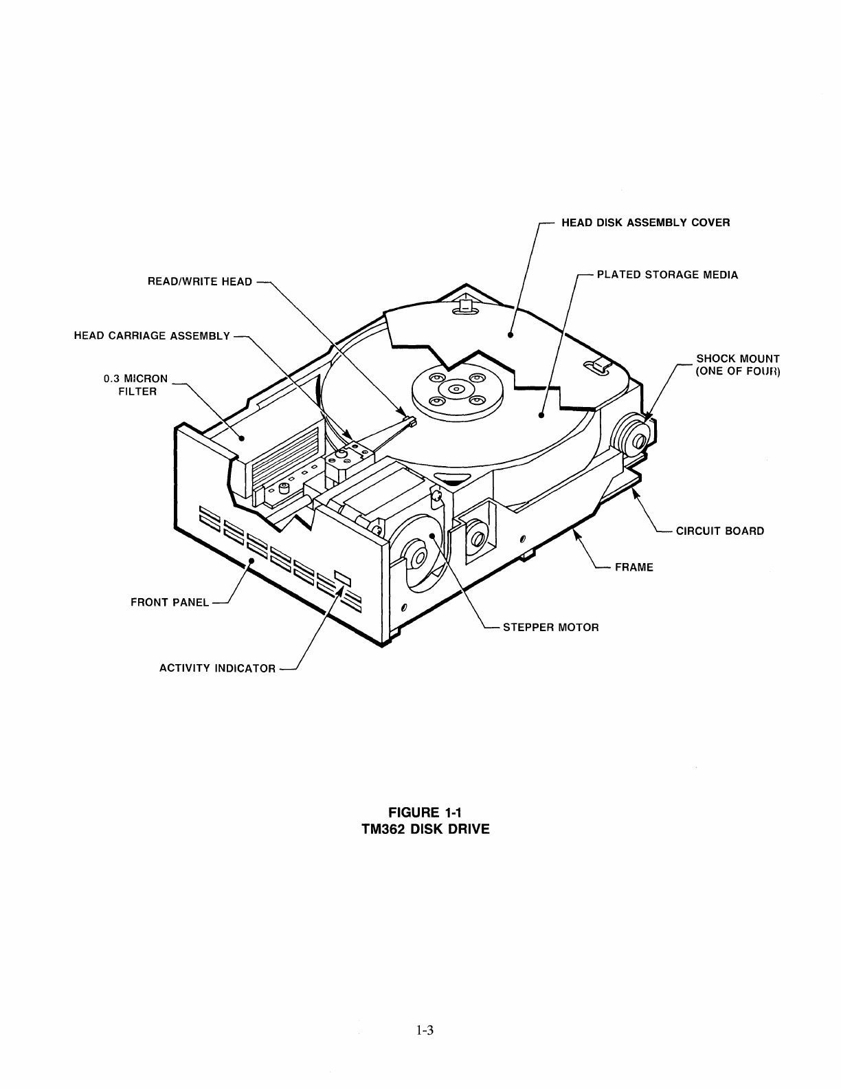
1.5 PHYSICAL DESCRIPTION
The TM362 and TM262 drives differ only in the
physical dimensions
of
their frames. The TM362 uses
the smaller frame, and the TM262 the larger.
The TM362 drive
is
shown in Figure
1-1
and the TM262
drive in Figure
1-2.
Both drives contain 3.5-inch storage
media.
The
head
disk
assembly
and the
read/write
preamplifiers are enclosed in a sealed cast aluminum
housing, which includes an air
fil~ration
system
to
en-
sure a contamination-free environment. The housing
is shock mounted to a metal frame. A front panel may
be attached to either drive. Threaded holes are provid-
ed on the sides and bottom
of
the frame for mounting
the drive onto a chassis.
In addition, both drives include read/write control elec-
tronics and servo spindle control electronics.

READ/WRITE HEAD
HEAD CARRIAGE ASSEMBLY
0.3 MICRON
FILTER
ACTIVITY INDICATOR
FIGURE
1-1
TM362 DISK DRIVE
1-3
HEAD DISK ASSEMBLY COVER
PLATED STORAGE MEDIA
STEPPER MOTOR
SHOCK MOUNT
(ONE
OF
FOUn)
CIRCUIT BOARD

READ/WRITE HEAD
HEAD CARRIAGE ASSEMBLY
0.3 MICRON FILTER
ACTIVITY INDICATOR
FRONT PANEL
HEAD DISK ASSEMBLY COVER
PLATED STORAGE MEDIA
FRAME
SHOCK MOUNT
(ONE OF FOUR)
CIRCUIT BOARD
STEPPER MOTOR
FIGURE 1-2
TM262 DISK DRIVE
1-4

SECTION 2
PRODUCT SPECIFICATIONS
INTRODUCTION
This section contains the mechanical, electrical and operational, reliability, and environmental specifications
for the TM362 and TM262 drives. Other than their physical dimensions and nonoperating shock specifications
both drives are identical.
2.1
MECHANICAL SPECIFICATIONS
The mechanical and physical dimensions
of
the TM362 and TM262 drives are contained in
Figures
2-1
and 2-2, respectively.
2.2 ELECTRICAL AND OPERATIONAL SPECIFICATIONS
The electrical and operational specifications are contained in Table 2-1.
2.3 RELIABILITY SPECIFICATIONS
The reliability specifications are contained in Table 2-2.
2.4 ENVIRONMENTAL SPECIFICATIONS
The environmental specifications are contained in Table 2-3.
2.5 RECOGNITION AND CERTIFICATION
This product is recognized under U. L. EMRT2, Component, Data Processing Equipment,
Electronic, and certified under ~® Standard Number' C22.2.
Ia n aD n CORPORATION, CHATSWORTH, CALIFORNIA 91311
2-1
179070·001
REVISION A

.050
±
.010
5.75
±
.02
f
1.725
±
.010
.627
±
.020
----.
2.362
±
.010
-.
.354
±
.020
~
2.752
±
.010
4.100
±
.010
.050
±
.010
NOTE: ALL DIMENSIONS ARE
IN
INCHES
WEIGHT
IS
APPROXIMATELY 1.8 LBS
FIGURE
2-1
/
?
----.-t
1.625
±
.020
6-32
UNC
2B
BY
.20 DEEP
MAXIMUM
8 PLACES
1 1
4.00
±
.02
3.504
±
.010
TM362 DISK DRIVE OUTLINE DRAWING
Ia n aD n CORPORATION, CHATSWORTH,
CALIFORNIA
91311
2-2
179070-001
REVISION A

1.87
±
.02-.
.070 1
f t
1.69
1.37
± .02
m
5.88 ±
.01
.065 ± .01
NOTE:
ALL DIMENSIONS ARE
IN
INCHES
OJ
7.34
3.120
± .02
3.120 ± .02
---..
.86 ±
.01
6-32 UNC-1 B
16 PLACES
1.62
(NO DEPTH RESTRICTIONS)
6-32 UNC-1 B
L BY .18 DEEP MAXIMUM
8 PLACES
5.750 ± .02
5.500 ± .02
rn
ADD .160 TO GET TRUE FRAME LENGTH
WHEN
NOT USING FRONT PANEL
WEIGHT
IS
APPROXIMATELY 2.3 LBS
FIGURE 2-2
TM262 DISK DRIVE OUTLINE DRAWING
Ia n aDn CORPORATION, CHATSWORTH,
CALIFORNIA
91311
2-3
179070-001
REVISION A

TABLE
2-1
ELECTRICAL
AND
OPERATIONAL SPECIFICATIONS
Media
Tracks Per Inch
Spacing, track to track
Number
Of
Cylinders
R/W
Head Parking Cylinder
Number
Of
Tracks
Disk Speed
Average Latency
Motor Start Time
Seek Time, track to track
Head Settling Time
Average Track Access Time, using buffered
seek, including head settling time
Maximum Access Time, using buffered seek,
including head settling time
Transfer Rate
Maximum Flux Reversals
Per
Inch (FRPI)
Unformatted Recording Capacity
Per
Drive
Unformatted Recording Capacity Per Surface
Unformatted Recording Capacity
Per
Track
3.5-inch rigid disks (2)
804 TPI
1.24 milinches
615 data cylinders
663
2,460
tracks
3,568
RPM ± 0.5 percent
8.41 milliseconds
15
seconds, typical
3 milliseconds
15
milliseconds
80 milliseconds
195 milliseconds
5.0
megabits per second
13,810 FRPI
25 megabytes
6.25 megabytes
10.4 kilobytes
Ia n aD n CORPORATION, CHATSWORTH, CALIFORNIA 91311
2-4
179070·001
REVISION A

TABLE
2-1
(CONTINUED)
ELECTRICAL AND OPERATIONAL SPECIFICATIONS
POWER REQUIREMENTS
Start Up: +
12
volts D. C. ± 5 percent, 2.0 amperes maximum, not to exceed
10
seconds.
+ 5 volts D. C. There
is
no surge current on the + 5 volt D. C. line.
Running: +
12
volts D. C. ± 5 percent, 0.8 ampere maximum, with
no
more than 100 millivolts Perodic
and Random Deviation (PARD).
+ 5 volts D. C. ± 5 percent
0.6
ampere maximum, with no more than 100 millivolts Periodic and
Random Deviation.
POWER DISSIPATION
Power requirement at 5.0 volts and 12.0 volts is 10.0 watts typical.
POWER
SEQUENCING
No power sequencing is required. The microprocessor starts the spindle motor when both voltages are present.
Ia n aDn CORPORATION, CHATSWORTH, CALIFORNIA 91311
2-5
179070-001
REVISION A

TABLE 2-2
RELIABILITY SPECIFICATIONS
SOFT AND HARD READ ERROR RATES, EXCLUSIVE OF MEDIA DEFECTS
For
data that has been verified previously as
error
free, and when used in conjunction with a data separator
and phase lock loop
of
good design, the recoverable (soft) read
error
rate for any subsequent read operation
shall not exceed one
error
in
1 x
10
10 bits transferred. A recoverable read
error
is an
error
that may be corrected
within five attempts to reread the data.
The nonrecoverable (hard) read error rates shall not exceed one error
in
1 x
10
12 bits transferred. A nonrecoverable
read
error
is
an
error
that may not be corrected within five attempts to reread data, providing that the writing
of
the data previously has been verified as correct. The seek
error
rate
is
not to exceed one
error
in 1 x
10
6 seeks.
MEDIA DEFECTS
Any defects on the media surface will be identified on a defect map provided with each drive. This defect map
will indicate the head number, track number, and the number
of
bytes from index for each defect. Each defect
shall be no longer than
16
bits. Cylinders 000 and 001 are guaranteed
error
free.
The defect map
is
offered as a guide only. The number
of
defects and their locations can change due to customer
system variations, such as data separators.
Mean Time Between Failures
Mean Time To Repair
Component Design Life
Preventative Maintenance
NOTE
A parking track is located at cylinder 663,
to reduce the probability
of
damage to data
tracks during extreme shock conditions.
15,000 power on hours
30 minutes
5 years
Not Required
Ia n aDn CORPORATION, CHATSWORTH, CALIFORNIA 91311
2-6
179070-001
REVISION A

Ambient Temperature
Operating
Nonoperating
Temperature Gradient
Operating
Nonoperating
Maximum Wet Bulb Temperature
Relative Humidity
Elevation
Operating
Nonoperating
Shock
Operating, read/write
without exceeding error rate
Operating, no damage
TABLE 2-3
ENVIRONMENTAL SPECIFICATIONS
4°C
to 50°C, 39
of
to
122
of
-40°C to 60°C, -40°F to 140°F
10°C per hour,
18
of
per hour
Below that causing condensation
26°C, 78
of,
without condensation
8-to-80 percent, noncondensing
Density Altitude:
-457 to 2,972 meters
-1,500 to 9,750 feet
-457 to 12,195 meters,
-1,500 to 40,000 feet
10G for
11
milliseconds (any
axis, half sine wave)
20G for
11
milliseconds (any axis, half sine
wave)
Ia n aD n CORPORATION, CHATSWORTH, CALIFORNIA 91311 179070-001
REVISION A
2-7

TABLE 2-3 (CONTINUED)
ENVIRONMENTAL SPECIFICATIONS
Nonoperating, heads over landing cylinder
TM362
TM262
Vibration
Operating
Nonoperating
40G for 25 milliseconds (any axis, square
wave)
40G for 25 milliseconds (any axis, half sine
wave)
.048 inch double amplitude (5-17 Hertz)
.73G,
17
to
150 Hertz
.33G, 200
to
500 Hertz
1.0G, 5 to 200 Hertz, sweep rate
of
.067
decades per minute
Ia n aD n CORPORATION, CHATSWORTH, CALIFORNIA 91311 179070-001
REVISION A
2-8

SECTION 3
OPERATION
INTRODUCTION
This section contains information pertinent
to
the handl-
ing, inspection, installation, and operation
of
the
TM362 and TM262 drives.
Each drive is shipped in a protective container which,
when bulk packaged, minimizes the possibility
of
damage during shipment.
The following procedures give instructions for unpack-
ing typical single-pack and multi-pack shipping
containers.
3.1
HANDLING
The drive may be damaged
if
it
is
subjected to excessive
shock, and, consequently, not meet published perfor-
mance specifications for data reliability, margins, and
function.
CAUTION
Take care to prevent the drive from be-
ing damaged by electrostatic discharge.
As
an
additional safety factor, it
is
recommended that:
1.
Drives are shipped only with heads positioned
over the parking cylinder.
2. Individual drives are handled carefully;
e.
g.,
receiving and in-process personnel are properly
trained, surface mats are used on working sur-
faces to prevent the possibility
of
"handling
shock'" and padding
is
placed on racks and
carts.
3-1
CAUTION
The critical aspects
of
handling these
drives must be emphasized. Tandon pro-
vides technical assistance on packing and
handling to customers upon request.
3.2 UNPACKING THE DRIVE
For Typical Single-Pack Containers (Figure 3-1)
1.
Place the single-pack container on a flat work
surface.
2. Visually inspect the shipping container for
damage.
3. Cut the tape on the shipping container.
4. Remove the foam lid and pads from the ship-
ping container.
5. Remove the inner container.
6. Remove the drive from the inner container.
7. Remove the drive from the anti-static/dust pro-
tective bag and place the drive on a ground-
ed, foam-covered surface.
8. Notify the carrier immediately
if
any damage
is found.
For Typical Multi-Pack Containers (Figure 3-2)
1.
Place the multi-pack container on a flat surface.
2. Visually inspect the container for shipping
damage.
3. Open the shipping container.

4. Remove the inner container.
5. Remove the packaged drives from their foam
cells.
6. Remove the drives from their anti-static/dust
protective bags and place the drives on a
grounded, foam-covered surface.
7. Notify the carrier immediately
if
any damage
is found.
CAUTION
Do not manually rotate the spindle or step-
per motors. Damage to the heads and
disks may result.
NOTE
The inside chamber
of
the drive
is
a sealed
compartment that must not be opened.
When returning a drive to the service center, ensure
that the heads are parked at cylinder 663. Head park-
ing
is
a function
of
the controller card. Use the prior
steps
in
reverse order. Be sure the drive
is
packed in
its anti-static/dust protective bag.
3.3 PREINSTALLATION
CHECKOUT
Before applying power to the drive, inspect for the
following:
3-2
1.
The circuit board is secure.
2. The connectors are firmly seated.
3. There is no debris
or
foreign material between
the frame and the casting,
or
any part
of
the
drive.
4. The head/disk housing can move freely on the
shock mounts
of
the frame.
5. The termination resistor pack and jumperblock
are
firmly
seated
and in
the
correct
configuration.
3.4 MOUNTING THE DRIVE
The drive can be mounted in any vertical
or
horizon-
tal plane. On the TM362, eight 6-32 tapped holes are
provided for mounting: two on each side and four on
the bottom
of
the frame (see Figure 2-1). On the
TM262, twenty-four 6-32 tapped holes are provided
for mounting: eight on each side and eight on the bot-
tom
of
the frame (see Figure 2-2). The drive
is
manufactured with some critical internal alignments
that must be maintained. Hence, it
is
important the
mounting hardware does not introduce significant stress
on the drive.
Any mounting scheme in which the drive
is
part
of
the
structural integrity
of
the enclosure
is
not permitted.
Mounting schemes should allow for adjustable brackets
or
incorporate resilient members to accommodate
tolerances.
A sway space is required between the head disk
assembly and other assemblies in the user system to
allow for movement
of
the housing on its shock mounts,
0.060 inches, minimum.
This manual suits for next models
1
Table of contents
Other Tandon Storage manuals
Popular Storage manuals by other brands

Maxtor
Maxtor 1394 External Storage installation guide

SEMOOKII
SEMOOKII UHOO HBCA-3.6-5 user manual

Maxtor
Maxtor ATLAS 10K IV user manual

Sun Microsystems
Sun Microsystems Sun StorageTek SL24 Getting started

Verbatim
Verbatim Portable Hard DriveUSB 2.0 Series quick start guide

Renkforce
Renkforce 1170562 operating instructions

Panasonic
Panasonic RP-SMFB16GAK operating instructions

Quantum
Quantum Tape Drive SDLT 600A quick start guide

Tuffy
Tuffy 238 installation instructions

HP
HP Surestore HVD10 - Disk System Service guide

Brocade Communications Systems
Brocade Communications Systems 1606 Reference

Fujitsu
Fujitsu PRIMERGY S10 manual