SPECIFICATIONS
General
12 Bands plus Weather Channel
100 channels (20 ch x 5 Banks)
to 29.7 MHz (10 Meter Amateur Band)
to 50 MHz (VHF Low Band)
to 54 MHz (6 Meter Amateur Band)
to 136.975 MHz (Aircraft Band)
to 144 MHz (Military Land Mobile)
to 148 MHz (2 Meter Amateur Band)
to 174 MHz (VHF High Band)
to 420 MHz (Federal Government Land Mobile)
to 450 MHz (70-cm Amateur Band)
to 470 MHz (UHF Standard Band)
to 512 MHz (UHF "T" Band)
to 956 MHz (Public Service Except Cellular Band)
29
29.7
~'i-l./
0'
f·'1
(./:1'
50
~'
-{,
I,
__.,
j
71/,[)
'~i
108
C/'1
rJ",ÀU~7
137
---.
j
'C'-
'
r,
rr '
-
CfS6.0
M
riL
~:~
406
420
450
470
806
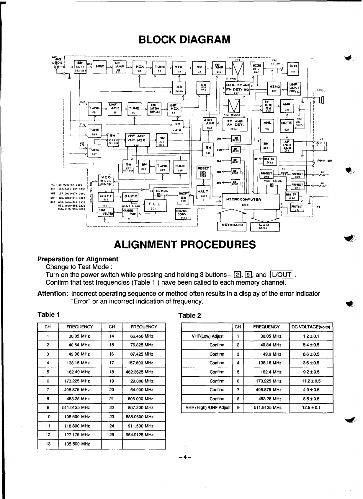
Frequency Range:
Band Coverage:
Display:
Weather Service Channel (162.400 to 162.550 MHz)
LCD (With Back Light) 10 Digits and special Annunciator
(Bank 1 - 5, Police, FIRE/EMG, AIR, WX, MRN, SCAN, MAN,
PGM, MON, UO, PRI, DLY, SRCH ...
T,
P)
Keys (PROGRAM):
(OPERATION):
Controls/Switches:
Total1 set 12 keys ("0" to "9", "ENTER", ".")
Total 16 keys (Scan, Manual, UO Decimal/Delay, Limit, Priority,
WX, s, V, Clear, Marine, Police, Fire, EMG, AIR, Program,
Monitor)
Volume Control, with Power ON/OFF Switch
Squelch Control
External Jacks:
Internal Speaker:
Power Requirements:
ANT. Jack (BNC Type)
Earphone Jack (3.5
<1»
8ohm,3W
12VDC ±10%
Operating Temp. :
Size:
Weight:
- 4°F (-20°C) - 140°F (60°C)
W:
6-1/4" (160 mm) x H : 1-5/8"
(41
mm) x D : 7-3/8" (188 mm)
2.2 1b
(1
kg)
M~asurement
Conditions
Power Source:
Antenna Impedance:
Test Temperature:
Modulation Frequency:
Deviation:
Mean Signallnput Level:
Audio Output Load:
Standard Ret, Audio Output:
12VDC
50 ohm
77°F(25°C)
1 kHz
FM±3 kHz Dev. &AM 60% tor Aircraft Band
100 I!V
8 ohm Resistive Load
125 mW (1V)
-2-