Tank Aquator User manual

TD_IM_009 Page 1 of 11
Rev 3
AQUATOR Commercial Oil Water Separator
Operating, Installation & Maintenance Manual
This Aquator Commercial Oil Water Separator (OWS) Operating and Maintenance Manual
gives instructions for single-wall and double-wall OWS applications. It must be used in
combination with the Tank Solutions Installation Manual and Operating Guidelines for Single-
Wall and Double-Wall Fiberglass Underground Storage Tanks. (According to EN 858-
2:2003E)
Some Notes from EN 858-2:2003 (E);
- The light liquid shall not be able to escape from separator or the extension shafts.
Separator systems shall be installed in such way that the level of the manhole cover
(ground level) is higher than the water level on the surface being drained. This is will
prevent the possible escape of light liquid from the system
Installation following EN 858-2:2003 (E);
- Separator system shall be only installed on drainage systems where light liquids need
to be separated from water and retained within the separator. They shall not be
installed on drain and sewer systems containing domestic wastewater.
- The drainage of areas where light liquids are unlikely to occur, such as roofs
and grassed areas should not discharge through separators.
- The connection of the separator system to the drainage system shall be done
in accordance with the local regulations.
- Sampling access shall be integral or separately installed, immediately downstream
of the separator.
- To avoid turbulence within the separator, pumping and lifting plants should be
installed downstream of the separator.
- The provision of traps on drains depends on local regulations. The drains as well as
the connected pipelines shall be installed to fall to the separator system.
- If for technical reasons long pipe runs are required for large collecting areas, e.g. tank
farms, army barracks, refineries, full pipelines may be necessary for special protection
of the drainage installations.

TD_IM_009 Page 2 of 11
Rev 3
Operation, Inspection and Maintenance
All parts which have to be regularly maintained shall be at all times accessible.
Inspections and maintenance of the Aquator should be carried out by experienced personnel at
three, six or twelve monthly intervals depending upon the site conditions. The maintenance
shall be carried out in accordance with the manufacturer’s instructions and should include the
following as a minimum;
a) Sludge trap
- determination of sludge volume
b) Separator
- measure the thickness of light liquids
- check the operation of the automatic closure device
- check the coalescing devices for permeability, if the water levels in front and behind
the coalescing device show significant difference
- check the function of the warning device
c) Sampling port
- clean the drain channel
Light liquid and sludge shall be removed as required. Before putting in service the Aquator
shall be filled with fresh water.
Note: emptying is recommended when on half of sludge volume or 80% of the storage
capacity of the separator is reached.
In exceptional circumstances, when personnel need to enter the separator, it shall be fully
drained and thoroughly ventilated.
The regulations / decrees for avoiding accidents and the handling of dangerous materials shall
be followed.
Every five years the separator shall be emptied and then submitted to general inspection
covering the following items;
- tightness of the system
- structural condition
- internal coating, if present
- state of inbuilt parts
- state of electrical devices and installations
- Checking of adjustment of automatic closure device.
The cleaning and maintenance records shall be kept and made available to the
authorities upon request and shall contain remarks on specific events (e.g. repairs,
accidents).

TD_IM_009 Page 3 of 11
Rev 3
INTRODUCTION
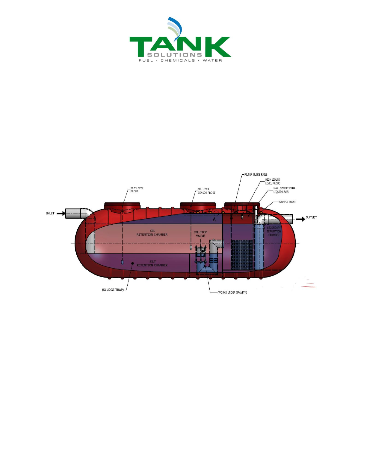
A Tank Solutions Aquator Commercial Oil Water Separator is a high-quality system for removing oil from
water. It is comprised of a standard single wall or double-wall tank that has been modified with piping and
internal components to separate oil from water.
It is important to follow the procedures and instructions in both this Aquator Manual and Tank Solutions
Installation Manual FRP Single Wall and Double Wall F935 (Installation Manual) in order to safely and
properly install, operate and maintain an Aquator and accessories. Failure to follow these instructions will
void the Aquator warranty and may cause Aquator failure, serious personal injury or property damage.
The Tank Solutions warranty applies only to an Aquator installed according to the instructions contained in
this Aquator Manual and the Installation Manual. Since Tank Solutions does not control the parameters of
any installation, Tank Solutions’sole responsibility in any installation is that presented in our warranty.
It is the responsibility of the owner and operator to always follow the operating and maintenance
guidelines set forth in Tank Solutions’applicable warranty. A Tank Solutions warranty is found in the
product brochure or is available upon request from Tank Solutions. It is the responsibility of the owner to
retain this AquatorManual and the Installation Manual for future reference to operating and maintenance
guidelines.
Use the Tank Installation Checklist (included in the Installation Manual) as the installation proceeds.
Retain a copy of the completed Tank Installation Checklist, and any correspondence, certification, etc.,
related to the Aquator. Each Aquator requires a separate Tank Installation Checklist. Consult your Tank
Solutions representative or distributor if additional Tank Installation Checklist forms is needed.
The Aquator owner should retain a copy of the Tank Installation Checklist to facilitate any warranty claim.
Tank Solutions recommends that the installing contractor also retain a copy.
It is important that this document is retained with the equipment for future reference. Should the
equipment be transferred to a new owner, always ensure that all relevant documents are supplied in
order that the new owner can be acquainted with the functioning of the equipment and the relevant
warnings.
For additional information, contact your state and local government authorities, including health, fire or
building departments, and environmental agencies. All work must be performed according to standard
industry practices and OH&S regulations. A Tank Solutions requirement will never take precedence over a
requirement imposed by any federal, state or local code or regulation. In all cases, any such requirement
takes precedence over any provision of the Tank Solutions manual. Tank Solutions must authorise any
variation to, or deviation from, these instructions. This authorisation must be made in writing, prior to tank
installation.
Comply with all applicable regulations and standards regarding the disposal of separated oil and solids.
Federal, state and local codes and regulations always take precedence over a Tank Solutions
requirement. Tank Solutions must authorize –in writing and prior to Aquator installation –any variation to,
or deviation from, these Aquator Manual instructions. All correspondence regarding variations must be
retained. If you have questions or encounter situations not covered in this Aquator Manual or the
Installation Manual, contact technical support at Tank Solutions.

TD_IM_009 Page 4 of 11
Rev 3
DEFINITIONS
For terms related to the Tank Solutions Aquator, see Figure 1-1, the drawing is for purposes of
terminology only.
Each separator will be allocated a nominal size (NS) according to the maximum flow that can be treated
to give, under the test conditions, an oil concentration of up to 5 mg/L (Class 1) in the discharge.
Emergency spill capacity is defined as the maximum amount of oil the Tank Solutions Aquator can store
(capture) in an emergency spill situation. A full retention separator is fitted with a device that will prevent flow
passing through the separator when the quantity of oil in the separator exceeds the oil storage volume (V).
Figure 1-1 –Aquator Class1 Oil Water Separator
Oil Stop Valve - A valve comprising a water buoyant element that is sensitive to any change in the water
density. In the event of light liquids accumulation, the valve automatically activates and isolates the retention
chamber such that pollutants are prevented from discharging to the drains and therefore the surrounding
environment.
Full Retention - All liquid entering the Aquator is treated. There is no by-pass possible.
Retention Chamber - The first chamber that the liquids enter where phase separation occurs. Silt falls to the
Silt Retention Chamber which reduces the Total Suspended Solids (TSS) content in the outlet. Oils (light
liquids) float to the surface. Water flows to and through the Oil Stop Valve.
Designed to promote non-turbulent flow through the Retention Chamber, utilising the density separation to
retain light liquids and suspended solids in all flow conditions.
Secondary Separation Chamber - The chamber that the water enters following the Retention Chamber.
Coalescing Filter - Provides a coalescing process for the separation of emulsified hydrocarbons to reduce the
light liquid content in the outlet to less than 5 mg/L.
Inlet - The inlet pipe is arranged to minimise incoming turbulence and to act as a flame trap to prevent
flammable and inflammable vapours passing into the drainage system.

TD_IM_009 Page 5 of 11
Rev 3
1. PREPARATION FOR INSTALLATION
Although Tank Solutions oil/water separators are rugged, the Aquator owner and/or tank owner’s
representative must take care so that the Aquator is not dropped or damaged during delivery, unloading
and handling on the job site.
See Installation Manual for specific instructions on unloading and handling the Aquator on the
job site.
See Installation Manual for specific instructions on inspecting the Aquator prior to installation.
In addition, remove the manway cover and inspect baffles, coalescing filter and internal piping for damage.
2. PRE-INSTALLATION TESTING
See Tank Solutions Installation Manual (FRP Single Wall and Double Wall F935) for instructions on
testing the Aquator tank on the job site.
3. BACKFILL MATERIAL
See Installation Manual for backfill instructions.
Do not exceed 50°C temperature in the Aquator or its contents. Excessive heat in the Aquator may result
in minor or moderate injury or in failure of or damage to the Aquator.
4. EXCAVATION PARAMETERS
See Installation Manual for excavation instructions.
5. ANCHORING TANKS
See Installation Manual for anchoring instructions.
6. INSTALLATION
See Installation Manual for installation instructions.
(For installations within Water Corporation of Western Australia, please refer to Appendix A)
In addition, install the Aquator in one of the following positions:
a) in a level and plumb position, or
b) with the outlet side 1/2 inch to 1 inch lower than the inlet side.
The Aquator is designed to be gravity-fed. If an installation requires a lift station, the lift station should be
located downstream of the Aquator.

TD_IM_009 Page 6 of 11
Rev 3
7. PIPING
See Installation Manual for piping instructions.
In addition, follow these instructions below:
All piping must be properly sized and influent piping must be gravity-fed.
Turbulence caused by improperly sized piping or pumping influent into the Aquator may damage
the Aquator, reduce its efficiency or require flow conditioners to augment the system.
Make sure the diameters of the connecting pipework are no larger than the diameters of the inlet nozzle
and the outlet nozzle.
Install expansion joints on any inlet or outlet tee/elbow connections.
All connections to the Aquator must be flexible. Provisions must be made to accommodate
movement and misalignment between the piping and the Aquator. Failure to do this may damage
the tank or surrounding property.
Slope the inlet pipework downward to the Aquator to establish a proper gravity flow.
Slope the outlet pipework downward away from the Aquator according to job specifications (typically
between 0.5–2.0 %) to establish a proper gravity flow.
Tank Solutions recommends installing a gross pollutant trap (GPT) large enough to collect debris (such as
leaves, gravel, sand, rags, etc.) upstream of the Aquator.
A valve can be installed upstream of the inlet tee / elbow connection.
A valve can be installed downstream of the outlet tee / elbow connection.
Make sure inlet valves have no valve seat or reductions and are the same size as the piping.
To prevent debris from entering the Aquator, plug the inlet piping and outlet piping until the drainage site is
paved and the GPT (if present) is installed.
If valves are installed, keep the valves completely open during normal operation.
8. VENTING
See Installation Manual for venting instructions. In addition, follow these instructions:
Vent the Aquator to atmospheric pressure to ensure proper operation.
Vent the Aquator inlet and outlet pipework to atmospheric pressure to ensure proper operation.
For instructions on venting an interstitial space (applicable in a double-wall Aquator),
See the section in Installation Manual on Venting Interstitial Space.
Provide flame arrestors when required by regulations and standards and when appropriate for safety
reasons.

TD_IM_009 Page 7 of 11
Rev 3
9. POST INSTALLATION TESTING
Perform any post installation testing required by the Installation Manual and by local codes.
10. FILLING THE AQUATOR
Open the Aquator inlet and outlet valves if present.
Fill the Aquator through the manway or inlet pipework.
Place the fill hose through the fitting and secure it so it does not spray directly on the coalescing filter.
Both chambers of the Aquator should be filled with clean water up to the invert level of the outlet pipe. It is
now ready for use.
If probes are present, Tank Solutions recommends that the Aquator be filled completely to check probe
operation during a start-up.
The Aquator shall be adequately vented to prevent the development of vacuum or pressure when
filling or emptying the tank. Failure to properly vent the Aquator could cause tank failure.
11. CONNECTING AQUATOR TO SENSORS
See Installation Manual for alarm instructions. (Darcy Spillcare Manufacture)
It is recommended that that the sensors and alarm unit be fitted, tested and commissioned by a licensed
electrician. This is to ensure that the excessive oil probe is calibrated correctly, raising an alarm when 90%
of the oil storage volume is reached. Should the oil level alarm fail to provide an early warning, excessive
oil could pass through the separator, thus polluting the environment.
12. OPERATING THE AQUATOR
Operating the Aquator as specified in this manual increases the efficiency and effectiveness of the Aquator.
Take ordinary fire prevention measures around separated oil to ensure that all flames, sparks and other
ignition devices and materials are kept away from the Aquator.
Safeguard against sparks or fire in the vicinity of the Aquator. Vapours and liquid oil may be
flammable and cause a fire or explosion.
Check oil level after every rainstorm or in accordance with local codes. Dispose of oil from the Aquator as
required by federal, state and local regulations and codes.
Do not collect “waste”oils in the Aquator as they may contain chemicals that may damage the
Aquator tank, pipework and internal components.
Remove oil only during non-flow conditions so that only oil is drawn off.

TD_IM_009 Page 8 of 11
Rev 3
13. MAINTAINING THE AQUATOR
The Aquator requires regular maintenance, including the following cleaning and inspection procedures,
to operate most efficiently and effectively.
Never enter the Aquator, the riser, the manway extension or any other enclosed space without
proper training and OSHA-approved equipment.
Aquator internal surfaces are slippery.
Ventilate all enclosed spaces according to methods described in applicable regulations and codes
before entering an Aquator to avoid asphyxiation or ignition of vapours or liquid oil, which are
flammable.
Perform maintenance at three, six or twelve monthly intervals depending upon the site conditions.
Under the following conditions, maintenance is required more frequently:
•
If the Aquator bottom sludge accumulation is more than 30 cm deep;
•
When the effluent water quality does not meet levels mandated by applicable federal, state and
local codes and regulations;
•
After a major oil spill has occurred.
Begin maintenance by cleaning the Aquator, using the following procedure:
Remove the coalescing filter for cleaning. Use normal water pressure, ensuring the dirty water runs back into
the drainage system leading to the Aquator.
Do not stand on the coalescing filter support grating. This grating is not designed to accept
loads and is slippery.
Sludge and debris should be removed from the Aquator using a vacuum truck.
Do not use picks, axes, hammers or other heavy tools or objects when breaking apart sludge in
the Aquator. Such tools may damage the Aquator.
Do not use detergent or soap.
Do not use soaps or detergents when cleaning the coalescing filter. Soaps or detergents may
damage the coalescing filter and/or reduce the efficiency of the Aquator.
Check the oil/water sensor (if installed) for movement.
Remove and clean the sensor as per manufacturers instructions if the sensors are fouled. This is usually
simply a matter of wiping and reinstalling.
Visually inspect the Aquator interior (walls, components and inlet piping) for damage. If you observe any
damage, contact the Tank Solutions.
If entry to the Aquator is required, remove all liquid from the Aquator and isolate all inlet and outlet pipework
and valves.
Properly dispose of oil removed from the Aquator as required by federal, state and local laws,
codes and regulations.
Failure to close inlet and outlet piping valves or plug the piping before entering the Aquator could
result in death or serious injury.

TD_IM_009 Page 9 of 11
Rev 3
Re-install the cleaned coalescing filter unit, support grating and retaining pieces.
If the coalescing filter unit is not properly installed, the Aquator will not work properly or efficiently.
Check to see that the coalescing filter unit is reinstalled properly. Improper installation may result
in damage to the Aquator and/or reduce its efficiency.
Attach the manway lid.
Refill the Aquator to at least half way by using clean water. (See SECTION 10 for instructions.)
OPTIONAL PROCESS FOR CLEANING THE AQUATOR
If it has been less than 12 months since last cleaning the Aquator and if only the bottom sludge has built
up and the effluent water is contaminant-free, the following procedure may be sufficient for proper
maintenance:
Vacuum out the sludge from silt chamber.
Recharge the Aquator by filling it to the invert level of the outlet pipe with clean water.
(See SECTION 10 in this manual.)
INSPECTING THE AQUATOR
Continue maintenance by performing the following inspections as usage and the site conditions require
Inspect and clean the GPT.
Inspect the inside of the Aquator looking for sand, trash, sludge and oil build-up.
Inspect effluent water for oils or other contaminants during or immediately after a heavy rainfall.
14. REMOVING AND CLEANING THE COALESCER
Keep spare coalescing filters covered or out of contact with ultraviolet light.
Ultraviolet light from sunshine may damage the coalescing filter if left exposed for extended
periods of time and may reduce the efficiency of the Aquator when installed.
Never enter the Aquator, the riser, the manway extension or any other enclosed space without
proper training and OSHA-approved equipment. Failure to follow this warning could result in
death or serious injury.
Remove the sludge from under the coalescing filter support grating in the coalescing chamber.
Remove the coalescing filter. Use normal water pressure, ensuring the dirty water runs back into the drainage
system leading to the Aquator.

TD_IM_009 Page 10 of 11
Rev 3
15. HANDLING A MAJOR OIL SPILL
When the oil exceeds the nominal oil storage capacity of the Aquator because of a spill, it may be
considered a major oil spill. Take the following actions:
Notify the authorities required by applicable federal, state and local regulations and codes.
Pump out the oil in the Aquator by following instructions in SECTION 13.
Charge the Aquator with clean water.
Wait one hour for possible oil-level build-up that may release from the coalescing filter
Check oil level again.
Repeat if necessary to make sure all oil is removed from the Aquator.
16. OPERATING GUIDELINES
See this manual and the Installation Manual for operating guidelines.
17. LIMITED WARRANTIES
Each product is covered by a product-specific limited warranty, which contain operating guidelines
and parameters that should be reviewed as applicable. Copies of the limited warranties are found in
Tank Solutions product brochures and are available upon request.
18. SELECTED LIST OF SUPPLEMENTAL MATERIALS
See Installation Manual for list of supplemental materials.
19. RETAINING THE AQUATOR MANUAL
After installation, tank installer must give Aquator Manual and Installation Manual to Aquator owner and operator.
After installation, tank owner must retain Aquator Manual and Installation Manual for future reference to operating
and maintenance guidelines.

TD_IM_009 Page 11 of 11
Rev 3
APPENDIX A
SPECIFIC INSTALLATION REQUIREMENTS FOR THE
WESTERN AUSTRALIAN
WATER CORPORATION
All Aquator installations in the Water Corporation network must be installed with a Trade Waste Sampling
Point (TWSP) on the Aquator outlet pipework.
See Water Corporation drawing number HX33-11-30 for details.
An example arrangement is shown below.
Table of contents
Popular Water Filtration System manuals by other brands

Livoo
Livoo DOM407AC1 instruction manual

Envirco
Envirco MAC 10 IQ RSR Operation & maintenance manual

Hydro International
Hydro International Up-Flo Operation and maintenance manual

Canature WaterGroup
Canature WaterGroup 89DF owner's manual

Apec Water
Apec Water WFS-1000 Installation instructions & owner's manual

TLV
TLV GAS1N instruction manual

Livpure
Livpure Glitz+ user manual

Moen
Moen UF1130 installation instructions

SpectraPure
SpectraPure PERFORMANCE PLUS MC-RODI-100-PPLUS Owner's Manual & Installation Instructions

Forbes
Forbes Neo user manual

Midea
Midea JL1645T-Z instruction manual

Canature WaterGroup
Canature WaterGroup AQUA FLO AQUV-12R22 owner's manual