Tannoy TX2 User manual

ELECTRONIC LOUDSPEAKER SYSTEM CONTROLLER
TX2
USER MANUAL

1
Contents
INTRODUCTION 2
OPERATING INSTRUCTIONS 2
Preliminary advice and information 2
Input connections 3
Output connections 3
Operation with and without a sub-bass system 3
SERVICING 5
Fuse replacement 5
List of spare parts 5
Warranty 5
TECHNICAL SPECIFICATIONS 6
Declaration of Conformity 7

2
INTRODUCTION
Thank you for purchasing the Tannoy TX2 loudspeaker system controller.
The TX2 is an advanced electronic controller intended to optimise the performance
of Tannoy loudspeaker systems. It can be used in full range mode where it performs
equalisation functions, extending the low frequency response of the system
significantly. Also, it can be switched to 2-way active mode for applications requiring
greater capability at very low frequencies, where it provides a mono sub channel
output with optimised high and low pass internal crossovers.
The TX2 also features :
•stereo operation.
•balanced inputs and outputs.
•individual sub level control.
•high pass filters to protect against hazardous ultra low frequencies.
•industry standard 19’’ rack-mounting
As well as technical specifications, this manual contains some helpful advice on how
to use the controller. Thank you for taking a few minutes to read it prior to
installation.
OPERATING INSTRUCTIONS
Preliminary advice and information.
The information contained in this manual is relevant for all TX2 controllers although
versions will vary with different internal adjustments for equalisation or cross-over
sections. Each version is dedicated for use with a specific Tannoy loudspeaker
system. Make sure that the controller you are planning to use is suitable for your
loudspeakers, as degradation of the sound quality and unreliable operation could
result from an improper combination.
Please inspect the unit immediately after unpacking for signs of transit damage. In
the unlikely event that this has occurred please inform the carrier and the supplier. It
is always a good idea to keep the carton for possible future transportation.
Before the TX2 is connected to the mains supply, make sure that the unit is
selected for operation with the correct mains voltage. This can easily be checked
by looking at the rear panel, where the selected input voltage appears on the voltage
selector itself, located near the mains socket. Where necessary, change the selection
by sliding the switch to the correct position. The position marked 115V is suitable for
any mains voltage from 100V to 120V, whereas the position marked 230V will suit
any voltage between 220V and 240V.
Figure 1. TX2 back panel

3
Input connections.
As with other devices of its type, the TX2 controller is inserted in the audio chain
between the last link of audio source (mixing console, preamp, CD player, etc.) and
the power amplifiers.
The two audio inputs are the 3 pin female XLR connectors on the rear panel, marked
Lfor left and Rfor right. On each connector the signal is received between pins 2
and 3 and pin 1 is grounded.
When the device connected at the input (e.g. console) and at the output (i.e.
amplifier) are both balanced, there is no hot and cold pin to worry about : the TX2 is
neutral polarity with pin to pin connections (pin 1 to pin 1, pin 2 to pin 2, pin 3 to pin
3). Note that pin 1 connection should be made using the cable shield.
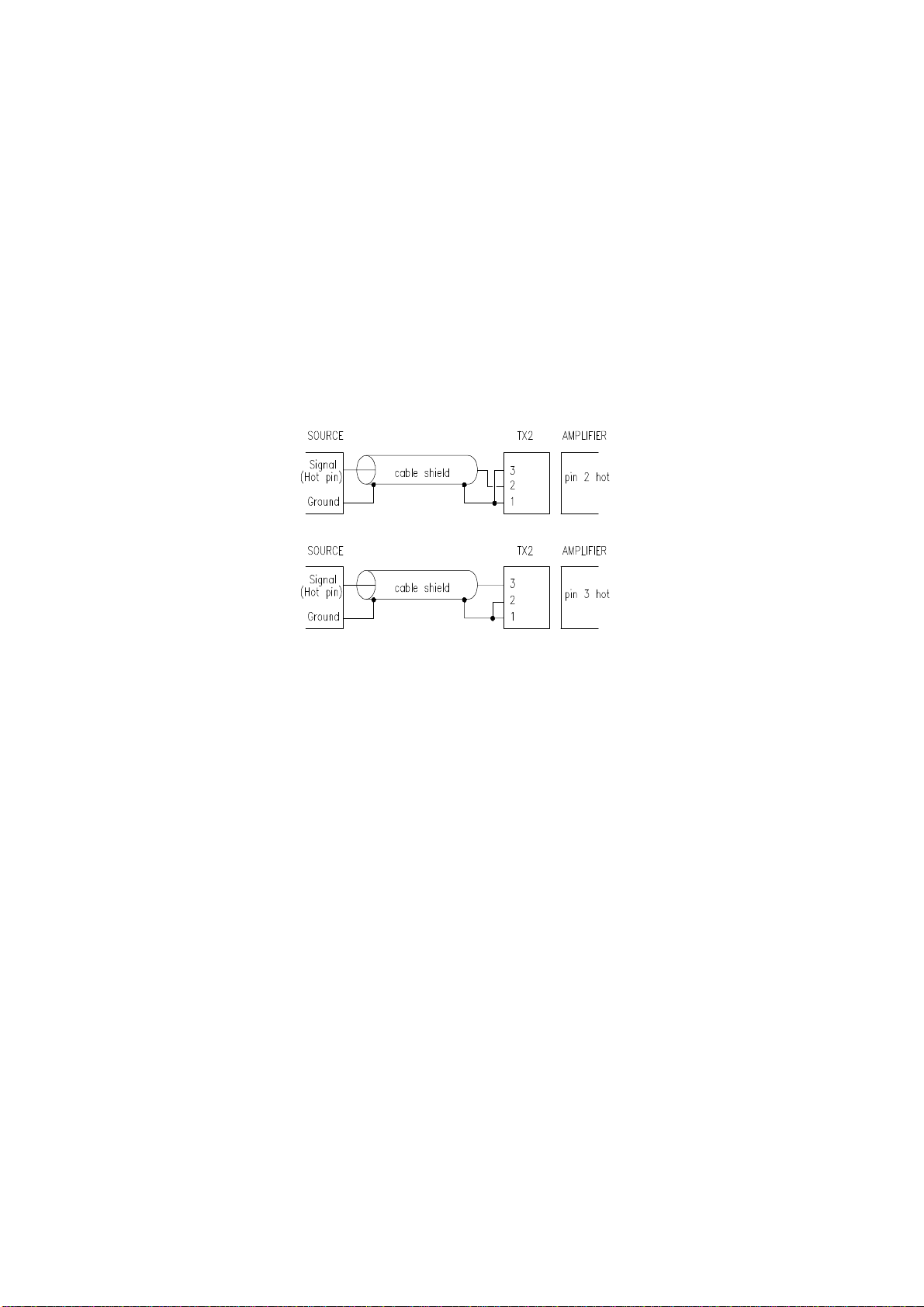
Where a device with an unbalanced output (e.g. hi-fi CD player or preamplifier) is
connected to the input of the TX2, the signal should be applied to either pin 2 or pin
3 of the input XLR, according to which pin is ‘hot’ on the amplifier connected at the
output. The unused signal pin (3 or 2 respectively) should then be linked to pin 1 for
grounding (see Fig. 2).
Figure 2. Input connections from an unbalanced source
Output connections.
The audio outputs are the three 3 pin male XLR connectors on the rear panel. Two of
them (marked Lfor left and R for right) are the output channels for the main system,
while the third one (marked MONO SUB OUT) is for the optional sub-bass system.
On each of these connectors the signal is applied between pins 2 and 3 and pin 1 is
grounded.
When devices connected at the input (e.g. console) and at the output (i.e. amplifier)
are both balanced, as said previously, the controller is neutral polarity with pin to pin
connections (pin 1 to pin 1, pin 2 to pin 2, pin 3 to pin 3).
Where amplifiers with unbalanced inputs are used, the hot pin of the amplifier input
should be connected to either pin 2 or pin 3 of the TX2 output XLR, according to
which pin is ‘hot pin’ on the device connected at the input. The unused signal pin (3
or 2 respectively) should then be linked to pin 1 for grounding.
Note however that the use of amplifiers with unbalanced inputs - rather unusual for
professional products - is not recommended, among other drawbacks it will cause the
level to drop by 6dB on the outputs of the controller.
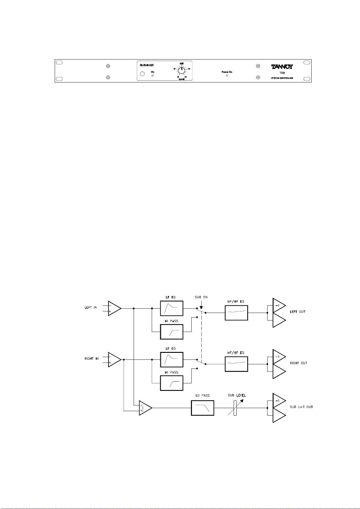
Operation with and without a sub-bass system.
The unit should be powered (green LED showing on the front panel) before being
connected , or the amplifiers should be turned off, to avoid any switch noise or power
surge that could damage the loudspeakers. Similar precautions should be taken
when power is switched off.

4
Figure 3. TX2 front panel
The way the TX2 operates with and without the sub-bass system can be seen on the
simplified block diagram of Fig. 4.
When the front panel push-button (left side of the SUB-BASS window) is depressed,
the main - left and right - channels operate full range with the signal passing through
the LF EQ section, resulting in an extension of the bottom end response of the
system. This section consists of a ‘High Q’ 2nd order high pass filter which provides
electronic boost where required and also cuts very low frequencies.
When the switch is pushed in, with the adjacent red LED coming on, the LF EQ
section is bypassed and the signal on each main channel is re-routed via a high-pass
filter at 100Hz designed to provide an optimised acoustic summation for the sub-
bass system.
On the sub-bass channel, signals from both left and right inputs are summed
together, and the resulting mono signal is low-pass filtered before being sent through
the level control section.
To sum up: the push-button should be ‘in’ when a sub-bass system is used, ‘out’
when not.
However it should be noted that the sub-bass channel itself is not affected by the
position of the switch, which means that it is possible to have the main system
operating full range while the sub-bass is also in operation. In that configuration both
systems would overlap over a wide bandwidth, with a large phase cancellation.
Reversing the polarity on the sub overlapping the main system would on the other
hand give an excess of energy in the 60-100 Hz range, but to the detriment of sound
accuracy, headroom and sensitivity to spatial alignment of the loudspeakers.
Figure 4. TX2 simplified block diagram.
This manual suits for next models
1
Table of contents
Other Tannoy Recording Equipment manuals