manuals.online logo
Brands
  1. Home
  2. •
  3. Brands
  4. •
  5. Tannoy
  6. •
  7. Recording Equipment
  8. •
  9. Tannoy VNET SC1 User manual

Tannoy VNET SC1 User manual

User Guide
VNETTM USB AND RS232 INTERFACE
IMPORTANT SAF TY INFORMATION
Please read carefully and keep the following instructions and safety information. Heed all
warnings and follow all instructions.
1. Do not remove covers. There are no user-serviceable parts inside; please refer servicing
to qualified service personnel.
2. This equipment must be earthed.
3. Protect the power cord from being walked on or pinched, particularly at plugs,
convenience receptacles, and the point where they exit from the apparatus.
4. Only use attachments/accessories specified by the manufacturer.
5. Servicing is required when the apparatus has been damaged in any way, such as the
power supply cord or plug is damaged, liquid has been spilled or objects have fallen into
the apparatus, the apparatus has been exposed to rain or moisture, does not operate
normally, or has been dropped.
2
3
IMPORTANT SAFETY INFORMATION
Please read carefully and keep the following
instructions and safety information. Heed all
warnings and follow all instructions.
•Do not remove covers. There are no
user-serviceable parts inside; please
refer servicing to qualified service personnel.
• Only use attachments/accessories specified
by the manufacturer.
•Servicing is required when the apparatus has
been damaged in any way, such as liquid has
been spilled or objects have fallen into the
apparatus, the apparatus has been exposed to
rain or moisture, does not operate normally, or
has been dropped.
QUICK START
• Install the drivers
• Connect computer via USB or RS232
• Apply power if using RS232
• Connect devices via RJ45 cables
REGULATORY COMPLIANCE
This product complies with the MC Directive
(89/336/ C) as issued by the Commission of the
uropean Community.
Compliance with these directives imply conformity
with the following uropean standards:
• N55103-1 lectromagnetic Interference
( mission)
• N55103-2 lectromagnetic Susceptibility
(Immunity)
This product is intended for operation in the 2
(commercial & light industrial) and 3 (urban
outdoors) lectromagnetic nvironments.
THANK YOU
Thank you for choosing this product for your
application. Please spare a little time to study the
contents of this guide, so that you obtain the best
possible performance from this unit.
UNPACKING
After unpacking the unit please check carefully for
damage. If damage is found, please notify the
carrier concerned at once. You, the consignee,
must instigate any claim. Please retain all
packaging in case of future re-shipment.
INTRODUCTION / KEY FEATURES
This product gives your Personal Computer
connectivity to a network of VN T™ equipped
devices so they can be controlled and monitored.
The VN T™ Interface can connect via USB or Serial
(RS232).
VN T™ is a fast networking topology using standard
Cat5 cabling to interconnect compatible devices
using a simple cabling scheme. The total span of
the network may be at least 1km without repeaters.
There is no maximum length for a single span
within this limit.
Housed in a convenient, rugged steel case, it can
be used free-standing or, using the rack-mount kit,
may be racked along with up to two additional
accessory products in 1U rack-space.
FEATURES:
• Rugged steel enclosure
• Free-standing or rack-mount options
• Rugged thercon network connectors
• Self-powered (using USB)
• Capable of driving 1km of network cable
• No special cables
COMPUTER SYSTEM REQUIREMENTS
Minimum requirements:
• PC with Pentium processor
• 32-bit Windows tm operating system (NT, 2000,
XP, Vista).
• CD-ROM drive or Internet access
• RS232 or USB port *
*Note that the network will operate slightly more
quickly when using RS232, so this is the preferred
method of connection.
INSTALLING THE SOFTWARE
If you only want to use the VN T™ Interface with
the Serial (RS232) port of your computer, you do
not need to install any drivers. If you wish to use
USB, then you need to install USB drivers for this
product.
When you plug the USB connection of the VN T™
Interface into a computer for the first time, the
computer will say “Found new hardware”, and will
prompt you to install drivers for it. Two drivers will
be installed: One for the USB port itself, and one for
the Virtual Com Port (VCP). Note that both of these
drivers may report that they have “Not passed
Windows Logo Testing”. You should select
“Continue Anyway”.
If the driver software has been supplied to you on a
CD-ROM, place this in your CD-ROM drive.
Alternatively, download the drivers from your
vendor’s web site.
VN T INT RFAC US R GUID
4
WINDOWS 2000 DRI ER INSTALLATION
You need to have administrator privileges to install
any new drivers under Windows2000. To install the
driver or update the configuration please log onto
Windows 2000 as "Administrator" or ask your
system administrator to install the USB driver.
Please proceed with the following steps to install
the driver:
1. Connect a USB cable from your computer
(or USB hub) to the USB port of the Interface.
2. The connection brings up "Found New
Hardware Wizard".
3. Click "Next".
4. Select "Search for the best driver for
my device", and click "Next".
5. Select "Specify a location" and click "Next".
In the "Copy Manufacturer's file from", type "D:"
where "D:" is the location of your CD-ROM
(or browse to where you have copied the
drivers if you have downloaded them from
a web site).
6. Windows driver file searches for the device
"USB VN T™ Interface".
7. Click "Next" to continue.
8. Windows has finished installing the software.
Click "Finish" to complete the first part
of installation.
9. The "Found New Hardware Wizard" appears
again, and will complete the installation for the
device "USB VN T™ Port".
10. Repeat step (4) to (8) to complete installation.
WINDOWS XP DRI ER INSTALLATION
Please proceed with the following steps to
install the driver:
1. Connect a USB cable from your computer
(or USB hub) to the USB port of the Interface.
2. The connection brings up "Found New
Hardware Wizard".
3. Click "Next".
4. Select "Search for the best driver for my
device", and click "Next".
5. Select "Specify a location" and click "Next".
In the "Copy Manufacturer's file from", type "D:"
where "D:" is the location of your CD-ROM
(or browse to where you have copied the
drivers
if you have downloaded them from a web site).
6. Windows driver file searches for the device
"USB VN T™ Interface".
7. Click "Next" to continue.
8. Windows has finished installing the software.
Click "Finish" to complete the first part of
installation.
9. The "Found New Hardware Wizard" appears
again, and will complete the installation for the
device "USB VN T™ Port".
10. Repeat step (4) to (8) to complete installation.
COM PORT
The PodWare application uses a COM port to
communicate with the connected devices. When
you use the RS232 connection from your computer
to the VN T™ Interface, the COM port will be the
one which your computer normally uses for the
Serial (RS232) port; usually COM1.
When you use USB to connect from your computer
to the VN T™ Interface, the Driver software
causes a “Virtual COM Port” (VCP) to be created.
This will appear to PodWare as just another COM
port, and can be selected using Network > Com
Port. To find out the COM port which the VN T™
Interface is using, select Start > Control Panel >
System > Hardware > Device Manager > Ports.
Here, you should see an entry in the tree for an
item called “USB VN T™ Port. Against this will be
the COM port number
(e.g. COM5).
If you wish to change this to a different COM port
number, right-click on the existing COM port tree
node, select Properties > Port Settings >
Advanced. There, you will see a COM port selector.
Do not change it to a COM port which is already
in use.
EXTERNAL POWER SUPPLY
Provision is made to power the unit from an
external Tannoy VN T™ Accessory Power Supply.
An external supply is required in either of these two
circumstances:
• If it is desired to use an RS232 (serial)
connection to the PC
• If there are VN T™ network cable powered
devices anywhere on the network
If USB is being used and there are no such
VN T™ cable powered devices, no external supply
is required and the interface will be powered from
the computer’s USB port.
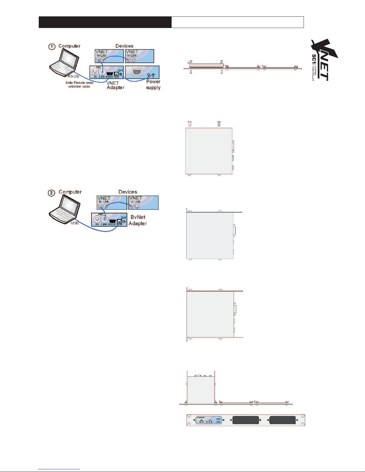
CONNECTING A COMPUTER
You can connect your computer to the NET
Interface in one of two ways:
RS232
If your computer has a native Serial (RS-232) port,
just connect this to the RS232 socket on the
VN T™ Interface using an RS-232 extension cable
(a straight-through female-to-male), as in diagram
1. When using RS232, it is necessary to supply DC
power to the VN T™ Interface from the companion
Accessory Power Supply product via the 3.5mm
jack cable provided with the power supply. This can
power either one or two compatible accessories.
ither the A or the B output on the Power supply
may be used since these are identical.™™™™
5
USB
You can connect your computer to the VN T™
Interface via USB using a USB Type A to USB Type B
cable as in diagram 2. It is not usually necessary to
use a Power Supply to power the VN T™ Interface
when using USB, since USB will supply sufficient
power for the Interface. If there are any Network
powered devices on the network however, then it will
be necessary to use the Accessory Power Supply.
CONNECTING DE ICES
Connect the VN T™ Link socket on the VN T™
Interface to the VN T™ In socket of the first device
you wish to control, then the VN T™ Link socket of
this device to the VN T™ In socket of the next
device, and so on. The order in which the devices are
connected is not important. The Link socket of the
last device in the ‘chain’ need not be connected. The
In socket of the VN T™ Interface is intended for
special applications, and would not normally be
connected. The ‘ thercon’ network connectors are
fully compatible with standard RJ45 thernet patch
cables which may be used to make these
connections. If additional ruggedness is required, we
recommend using the Neutrik thercon locking type
of connector.
RACKING
The VN T™ Interface and Accessory Power Supply
may be used free-standing. If you wish to mount
them in a 19-inch rack, then the Tannoy VN T™
accessory rack-mount kit may be used. To mount an
Accessory in the Mounting Kit panel:
1. Remove the two mounting brackets and blanking
sheet which are covering the aperture you wish to
mount the Accessory in, by removing the two nuts.
(Keep these and the screws and washers).
2. Remove the two screws from one side of the
Accessory.
3. Using the two screws removed in 2, attach one
mounting bracket loosely to the side of the
Accessory, with the ‘ear’ towards the front, pointing
outwards.
4. Repeat 2 and 3 for the other side. Now push the
lid towards the back of the unit as far as it will go then
align the bracket ears with the front edge of the lid.
Now tighten the screws.
5. Offer the Accessory with its mounting brackets up
to the reverse side of the Mounting Panel, and fix it in
place using the two sets of screws, washers and nuts
removed in 1.
Note that the holes at the rear ends of the brackets
may be used as cable tie-off points if desired.
VN T INT RFAC US R GUID
6
OPERATION
Once the VN T™ Interface has been connected to
the computer and to the devices (and if applicable,
to the optional VN T™ Power Supply) then there
are no further adjustments to make on the interface
itself. The indicators on the front of the unit operate
as follows
The XT Power indicator (1) will illuminate when
DC power is being applied to the XT Power socket
on the rear of the unit.
The N T Power indicator (2) will illuminate when
the unit is applying power to the network. This is
used for powering network-powered accessories,
and for signalling.
The USB indicator (3) will illuminate when the unit
has an active USB connection with a computer.
The Net DATA indicator (4) will illuminate when data
is being received from the network.
The Net TX indicator will illuminate when the unit is
transmitting data onto the network.
TROUBLE SHOOTING
The EXT Power indicator does not illuminate
If you are operating via RS232, you need to use the
Accessory Power Supply. Make sure this is
connected properly. Check if the power indicator on
the Power Supply illuminates. If you are operating
via USB (and there are no network-powered
devices on the network), it is not usually necessary
for an external power supply to be used, in which
case this indicator will not illuminate.
The USB indicator does not illuminate
Make sure the USB cable is plugged in both ends.
If you are using a USB hub, make sure it is capable
of providing sufficient power. You may need to use
a powered hub. Has the driver been installed?
Try unplugging the USB cable, then plugging it in
again.
If you are using RS232, this indicator will not
illuminate.
Cannot find the COM port for the USB device
Has the driver been installed?
Is the USB cable plugged in both ends?
Does the USB indicator illuminate? (Check above).
PodWare finds no devices
Have you selected the correct COM port in
PodWare?
Are the appropriate indicators illuminated?
(See above).
Make sure the network cable is not too long, is
correctly connected, and is not damaged.
Check that the Tx indicator flashes when PodWare
attempts to go online.
Will not operate via RS232
Have you selected the correct COM port in
PodWare?
You must use the Accessory Power Supply when
operating via RS232.
TECHNICAL SPECIFICATIONS
USB communication
Compliance 1.1 and 2.0
Power descriptor 150mA
Connector Type B
Serial communication
Compliance IA RS232C
Connector Female 9 pin ‘D’
(fully wired)
VN T™
Cable type Category 5 UTP
(or better)
Max. total cable length 1km
Max. Network Span 1km
Connector Standard RJ45
(or ruggedised
Neutrik ‘ thercon’)
xternal Power
Only to be provided by a Tannoy VNet
Accessory power supply via a 3.5mm
jack-to-jack lead.
Power consumption
USB powered 750mW max.
xternally powered 3W max.
nvironmental
Temperature 0 to +45°C
Humidity 0 to 80% RH
(non-condensing)
Dimensions
Height 43mm
Width 115mm
Depth 115mm
Weight 500g
7
NOT S
Tannoy Un ted K ngdom T: 00 44 (0) 1236 420199 E: enqu r [email protected]
Tannoy North Amer ca T: 00 1 (519) 745 1158 E: nqu r [email protected]
Tannoy Deutschland T: 00 49 (0180) 1111 881 E: [email protected]
Tannoy France T: 00 33 (0)1 7036 7473 E: [email protected]

Other manuals for VNET SC1

1

Other Tannoy Recording Equipment manuals

Tannoy Vnet USB RS232 Interface User manual

Tannoy

Tannoy Vnet USB RS232 Interface User manual

Tannoy VNET SC1 User manual

Tannoy

Tannoy VNET SC1 User manual

Tannoy TX2 User manual

Tannoy

Tannoy TX2 User manual

Tannoy Vnet User manual

Tannoy

Tannoy Vnet User manual

Popular Recording Equipment manuals by other brands

LA Audio DPF3103 Operator's manual

LA Audio

LA Audio DPF3103 Operator's manual

Pfeiffer Vacuum ASI 35 operating instructions

Pfeiffer Vacuum

Pfeiffer Vacuum ASI 35 operating instructions

Focusrite Liguid MX user guide

Focusrite

Focusrite Liguid MX user guide

Ramsey Electronics TATTLE-TALE TT1 instruction manual

Ramsey Electronics

Ramsey Electronics TATTLE-TALE TT1 instruction manual

Visonic SP-5A installation instructions

Visonic

Visonic SP-5A installation instructions

FONESTAR SR-1590 instruction manual

FONESTAR

FONESTAR SR-1590 instruction manual

DMX4ALL DMX-Audio Unit user manual

DMX4ALL

DMX4ALL DMX-Audio Unit user manual

Wheatstone Corporation A-2000 Technical manual

Wheatstone Corporation

Wheatstone Corporation A-2000 Technical manual

Waves CA1000 Getting started guide

Waves

Waves CA1000 Getting started guide

Fingertech Robotics tinyMixer instructions

Fingertech Robotics

Fingertech Robotics tinyMixer instructions

Unika PRO Series user manual

Unika

Unika PRO Series user manual

Koma Elektronik FT201 user manual

Koma Elektronik

Koma Elektronik FT201 user manual

Power Dynamics PDC-35 user manual

Power Dynamics

Power Dynamics PDC-35 user manual

Roland EF-303 owner's manual

Roland

Roland EF-303 owner's manual

Kurzweil SP7 Grand Musician's guide

Kurzweil

Kurzweil SP7 Grand Musician's guide

Alesis Studio12R Service manual

Alesis

Alesis Studio12R Service manual

Antelope zenstudio+ owner's manual

Antelope

Antelope zenstudio+ owner's manual

National Instruments NI PCIe-8360 user manual

National Instruments

National Instruments NI PCIe-8360 user manual

manuals.online logo
manuals.online logoBrands
  • About & Mission
  • Contact us
  • Privacy Policy
  • Terms and Conditions

Copyright 2025 Manuals.Online. All Rights Reserved.