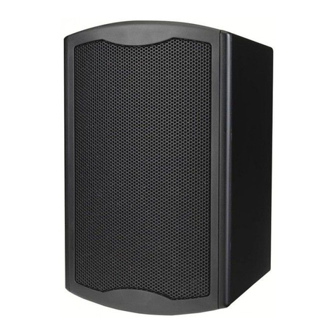
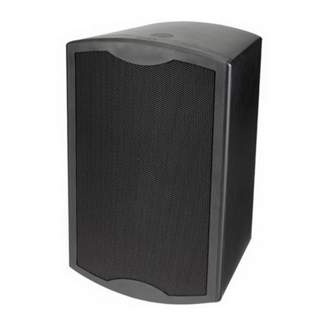
Tannoy HTS101 XP User manual

OWNER’S MANUAL
HTS101 XP

CONTENTS
WARRANTY 02 POSITIONING THE HTS101 XP SPEAKERS 05
INTRODUCTION 03 TECHNICAL SPECIFICATIONS 06
HTS101 XP SET UP GUIDE 03 SETUP DIAGRAMS 07-09
ASSEMBLING THE WALL BRACKETS 04
WARRANTY
No maintenance of the Tannoy HTS101 XP loudspeaker system is necessary.
Please register your Tannoy product online at www.tannoy.com.
All of our products have been produced and tested with care and precision to give rst-class service.
All passive components are guaranteed for a period of 5 years from the date of purchase from an authorised
Tannoy dealer subject to the absence or evidence of misuse, overload, or accidental damage. All active and
electronic components are guaranteed for a period of 2 years from the date of purchase from an authorised
Tannoy dealer subject to the absence of, or evidence of, misuse, overload or accidental damage. If at any time
during this warranty period the equipment proves to be defective for any reason other than accident, misuse,
neglect, unauthorised modication or fair wear and tear, we will repair any such manufacturing defect or, at our
option, replace it without charge for labour, parts or return carriage.
If you suspect a problem with a Tannoy product, in the rst instance, discuss it with your Tannoy dealer. If you
require further assistance then we ask that you deal directly with your local Tannoy distributor. If you cannot locate
your distributor please contact Tannoy Customer Services, at the address given below.
Customer Services, Tannoy Ltd., Rosehall Industrial Estate, Coatbridge, Strathclyde ML5 4TF, Scotland
Telephone: +44 1236 420199
Fax: +44 1236 428230
E-mail: enquiries@tannoy.com
DO NOT SHIP ANY PRODUCT TO TANNOY WITHOUT PREVIOUS AUTHORISATION.
Our policy commits us to incorporating improvements to our products through continuous research and
development. Please conrm current specications for critical applications with your supplier.
HTS101 XP
02_ HTS 101 XP MANUAL

HTS101 XP MANUAL_03
HTS101 XP
INTRODUCTION
Thank you for selecting Tannoy loudspeakers developed in the UK by our dedicated team of design engineers.
Tannoy is the brand of choice for discriminating music lovers around the world. Musical excellence is designed into
our loudspeakers from the start. Careful selection of the very best components combined with strict quality control
procedures in the production process ensures this level of excellence is maintained.
To gain maximum performance from your loudspeakers, please take time to read this owner’s manual in full before
installation. Once you have set up your new loudspeakers please complete and return the registration document or
register you product online at www.tannoy.com - this does not limit your legal rights.
Loudspeakers are electromechanical devices that ‘run-in’ through use; performance will therefore improve
after an initial period of 24 hrs use. Once they have been further run-in over a longer period, there will be clear
enhancement of the imaging, mid-band quality and bass performance characteristics. We are condent that you
will continue to enjoy your new Tannoy loudspeakers for many years to come.
HTS101 XP SET UP GUIDE
This high performance Tannoy loudspeaker system has been built and tested with care and precision to provide
rst class performance and reliable operation. To ensure maximum benet from ownership and for reasons of
safety, please read through all the information in this owner’s manual before operating and using this system for
the rst time. Tannoy HTS101 XP systems are primarily designed for use with the following equipment:
• An AV or Home Cinema Receiver with integral 5.1 decoder, 5 channel power amplier and a dedicated LFE or
subwoofer line level output.
• An integrated DVD player with 5.1 decoder, 5 channel power amplier and a dedicated LFE or subwoofer line
level output.
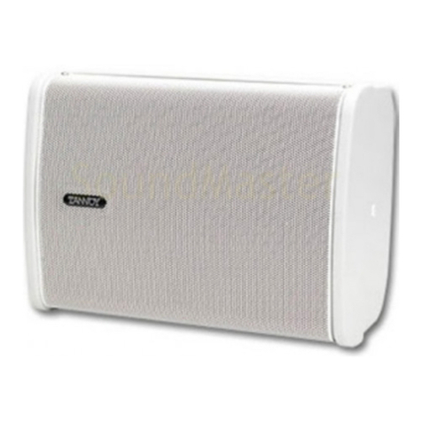
The speakers may be positioned in either portrait or landscape orientation, with the grille badge adjusted
accordingly. The centre channel is often more conveniently located in landscape format.
WARNING: Strong magnetic eld
Due to the powerful drive unit magnet, do not place within 1 metre (3 foot) of a cathode ray tube (CRT) television
or monitor. There is no issue with plasma, LCD and LED devices.
Each speaker provides a separate function. The functions are:
• Centre Speaker which carries most of the dialogue or solo performances.
• Front Left and Front Right Speakers which carry special effects and left/right stereo information.
• Left Rear and Right Rear Speakers which carry special effects information.
In addition, the TS2.8 subwoofer provides very low frequency sounds and special effects. The subwoofer supports
low frequencies for all 5 audio channels. Please refer to the separate Owner’s Manual provided with the subwoofer
for full instructions.

04_ HTS101 XP MANUAL
ASSEMBLING THE CENTRE & SATELLITE (HTS101) WALL BRACKETS
Fit the wall brackets to the smaller satellite speakers if you wish to wall mount them. (See Fig. 1)
• Locate the appropriate screws and lock washers in the accessory pack - 2 screws for each wall bracket.
• Locate the hex key tool which you will use to tighten the hex socket head screws.
• Each wall mounting bracket has two halves and a long pin which holds the two halves together to act as the hinge.
One half is mounted on the speaker using 2 screws and the other half is mounted on the wall using suitable
screws and wall plugs. It is your responsibility to ensure that the wall and the screw xing method are both strong
enough to support the weight of the satellite speakers. See the specication page for weights.
• Separate each bracket into two halves by removing the long hinge pin.
• Fit one half of the bracket with the large holes to the speakers using the screws and lock washers provided.
The threaded hinge pin hole in the bracket should face the terminals on the back of the speaker.
• Fit the 2 halves of the brackets to the centre speaker with the threaded hinge pin hole in the bracket facing the
terminals on the back of the satellite. This orientation will allow the hinge pins to be tted from either side of the
cabinet when mounting to the wall. Fit the other half of the bracket(s) to the wall using a suitable xing method for
the type of wall material - seek professional advice if unsure.
• Position the satellite or centre speaker (with half the wall bracket(s) tted) against the other half of the wall bracket
already tted to the wall. Line up the brackets so that the long screw pin can be inserted vertically from below the
satellite or horizontally from the sides of the centre speaker and screwed up lightly. The speakers will now swing in
the horizontal plane (vertical plane for the centre) for best aural and visual effect. Tighten the long pin to nish.
• To remove the speakers from the wall to access the wiring terminals, remove the long pin whilst carefully
supporting the weight of the speaker.
• Alternatively, self adhesive feet are provided for shelf mounting.

HTS101 XP MANUAL_05
HTS101 XP
11
12
13
14
15
16
17
18
19
20
5. POSITIONING THE HTS101 XP SPEAKERS
Place the speakers in positions relative to the viewing screen in your room. (See Fig. 2)
• Centre speaker close to, and either above or below the screen.
• Front Left speaker 1 to 2 metres (approximately 3 to 6 foot) to the left of the screen.
• Front Right speaker 1 to 2 metres to the right of the screen Try to get all 3 front speakers to be in the same
plane - the same distance from the viewing position and at least 300 mm (12 inches) away from any back wall
which may be present behind the screen. Left Rear speaker 1 to 2 metres behind the viewing position and to
the left.
• Right Rear speaker 1 to 2 metres behind the viewing position and to the right. Viewed from above, Front Left,
Front Right, Left Rear and Right Rear speakers should form a rectangle with the viewing position in the centre
of the rectangle.
• Place the subwoofer on the oor alongside the wall nearest to the screen. The exact position isn’t critical and
can be adjusted once the system is up and running. Refer to subwoofer Owner’s Manual.
This is an ideal positioning set-up, in practice there will be inevitable compromises depending on your room layout
and the furniture within it. Refer to your decoder or AV Home Cinema receiver instructions for further advice in
compensating for non-ideal situations.
6. CONNECTING THE HTS SPEAKERS TO YOUR A/V RECEIVER OR AMPLIFER
Connect the speakers to the AV Home Cinema receiver or separate amplier terminals. (See Fig. 3)
• Measure out suitable lengths of cable, to reach between the speakers and your AV or Home Cinema receiver
speaker output terminals.
• Wire up the system connecting each speaker to the appropriate terminals on the receiver or amplier making
quite sure that cables connect red to red terminals (+ to +) and black to black terminals, (- to -). Take care to
distinguish between left and right channels, and the front and rear channels, as seen from the viewing position.
This is a very important stage in setting up. Getting things wrong at this stage is the most likely reason for
disappointing results when troubleshooting the system.
7. CARE OF CABINET
The cabinets should only be cleaned with a dry cloth or with a light application of quality non-silicone furniture
polish.

06_ HTS101 XP MANUAL
TECHNICAL SPECIFICATIONS
PERFORMANCE
Recommended amplier powe r (watt RMS)
25 – 100
Sensitivity (2.82 volt @ 1m) 89 dB
Nominal impedance (ohm) 8
Frequency response (-6 dB) 100 Hz – 43 kHz
DRIVE UNITS
Co-axial high frequency 20 mm (0.78”) titanium WideBandTM
dome, with neodymium magnet
system
Co-axial Low frequency 100 x 65 mm (4 x 2.5” elliptical
paper cone
Magnetic shielding No
CROSSOVER
Crossover frequency 3 kHz (LF to HF)
CONSTRUCTION
Dimensions (H x W x D)
(excl grille)
185 x 100 x 109 mm
(7.3 x 4.0 x 4.3”)
Weight 1.4kg (3.1lbs)
ACCESSORIES
Supplied accessories Wall brackets, self adhesive feet

HTS101 XP MANUAL_07
HTS101 XP
SET-UP DIAGRAMS
Fig.1

08_ HTS101 XP MANUAL
SET-UP DIAGRAMS
Fig.2
-+ -+ -+ -+ -+
SUB OUT FRONT
LEFT
REAR
LEFT
CENTRE FRONT
RIGHT
REAR
RIGHT
AV RECEIVER/DECODER OUTPUT PANEL

HTS101 XP MANUAL_09
HTS101 XP
SET-UP DIAGRAMS
Fig.3
1.0 METRE
OR MORE
0.3 METRE
OR MORE
SUB
REAR
REAR
1 to 2 METRE
1 to 2 METRE
1 to 2 METRE
1 to 2 METRE
1 to 2 METRE

010_ HTS101 XP MANUAL
NOTES

HTS101 XP MANUAL_011
HTS101 XP
NOTES

6481 0679 / 190315
Tannoy Limited - product designed in the United Kingdom.
Tannoy adopts a policy of continuous improvement and product specication is subject to change.
All other trademarks remain the property of their respective owners.
tannoy.com
Table of contents
Other Tannoy Speakers System manuals

Tannoy
Tannoy iW Series User manual

Tannoy
Tannoy B475 User manual

Tannoy
Tannoy Arena HighLine 300 User manual

Tannoy
Tannoy SuperTweeter ST-100 User manual

Tannoy
Tannoy Arena Lite User manual

Tannoy
Tannoy CMS801 DC BM User manual

Tannoy
Tannoy Di5 DC User manual

Tannoy
Tannoy iw4DC User manual

Tannoy
Tannoy CMS501 User manual

Tannoy
Tannoy CVS6 User manual

Tannoy
Tannoy VQ 60 User manual

Tannoy
Tannoy HTS100 User manual

Tannoy
Tannoy BaseStation One User manual

Tannoy
Tannoy CMS801 DC BM User manual

Tannoy
Tannoy I6 AW ICT User manual

Tannoy
Tannoy VQ Series User manual

Tannoy
Tannoy Di5, Di5t,Di5 DC User manual

Tannoy
Tannoy B225 User manual

Tannoy
Tannoy Revolution XT User manual

Tannoy
Tannoy i6AW User manual