Tapco Port-O-Bender PRO-III User manual

© Copyright 2001 Price: $5.00
Featuring
• Accessories
• Setup and operating instructions
• How to form the most popular shapes
• Hints and shortcuts to greater profits
with your
Tapco
Pro-III®Port-O-Bender®
• Tune-up instructions
• Complete parts list
®
Pro-III Port-O-Benders are made under one or more of the following U.S. Patents:
3,161,223 4,321,817 4,651,553 4,489,583 4,493,200 4,445,356
4,372,142 4,766,757 3,817,075 4,557,132 4,240,279 4,671,094
3,482,427 4,494,397 3,559,444 5,343,728 5,353,620 5,505,069
Other U.S. & Foreign Pats. Pend.
®
PRO-III
®
Port-O-Bender
®
OPERATIONS MANUAL
TAPCO PRODUCTS CO.
A DIVISION TAPCO INTERNATIONAL
Tapco PRO-III Port-O-Bender
shown with optional
Tapco
Side-Winder, Pro-Filer,
Pro Cut-Off
and
Pro-Stand
.
The Industry Leader Since 1960

2
TheTAPCO PRO-III Port-O-Bender
The world’s best
selling portable bender
Tapco’s patented
“Moving Pivot”
hinge separates the
PRO-III
from
conventional brakes. It increases
leverage and lifting power and
eliminates scratching or
marring of materials.
(See page 15
for setup
Instructions).
Pro-Stand Features
•Durable lightweight anodized aluminum construction.
•Fast and easy height adjustments from 28" to 37".
•Heavy duty wheels handle the roughest of job site terrains
then convert to support pads.
•Detaches quickly from your Port-O-Bender.
•Fits all 8' 6" through 12' 6" Pro Series
Port-O-Benders and E-Z Angle
SidingTable.
Heavy Duty wheels
convert to foot pads
for solid support on
all terrains
EXCLUSIVE!
TAPCO OPERATION
VIDEO INCLUDED
®
•
Making the Most Common
Shapes on your Port-O-Bender
•Bending Techniques
•Mitres and Templates
•Shortcuts and Helpful Hints
•Care and Maintenance
SOLID
SUPPORT AND
PORTABILITY
TOO!
TAPCO PRO-STAND
™
Deluxe heavy duty transportable support
for your PRO-III, PRO 2000 Port-O-Bender,
and E-Z Angle Siding Table
A Comprehensive Guide to
Greater Profits with Your
TAPCO Port-O-Bender
®
®
Pro-III Features
★Computer designed die castings make this
the strongest portable bender ever!
★
Unique “Positive Toggle Locking
System” provides
positive clamping
without guesswork.
★
Widest mouth open
ing in the
industry
2
3
/
8
",
with built-in
Dual Working Pockets.
★
Patented
“Moving
Pivot” Hinge.
(See below)
®
▲
Full 14" Throat Depth ➤
➤
Built-in Dual
Working Pockets
➤
➤
Expanded Capacity!
Extra Wide Mouth
Opening
•Full 23/8" opening—
widest in the industry.
•For easier material
insertion.
•More flexibility in
forming complex
shapes.
U.S. & Foreign Pats. Pend.

3
PRO-III
®
PORT-O-BENDER
®
PARTS LIST
10094 1/4-20 Hex Flange Nut
10349 Coupling Nut
10351 Lifting Handle Assembly
10381 Pivot Assembly
10496 Pivot Arm - Left
10497 Pivot Arm - Right
10503 1/4-20 X 2 1/2" Sock Cap Screw
10508 Locking Handle Pin
10515 10-24 X 1/2" Pan HD Screw
10518 1/4-20 X 1 1/2" Sock FL HD Screw
10519 1/4-20 X 3/4" Hex Wash HD Screw
10520 1/4-20 Nylox Hex Nut
10521 Upper Link
10524 Lifting Handle Plug
10530 Rubber Pivot Pin Keeper
10531 Hemming Handle Plug
10532 3/8-16 X 3" Hex Cap Bolt
10534 3/8" Flat Washer
10535 3/8-16 Nylok Hex Nut
10536 3/8-16 X 2 1/4" Hex Bolt
10537 1/4-20 X 3/4" Sock Flat HD Screw
10538 3/8" Lock Washer
10539 1/4 X 1 1/4" Faspin
10540 Hemming Handle Assembly
10544 Lifting Handle Cap
10545 Moving Hinge Cap
Part Number Part Name
Part Number Part Name 10547 Base Hinge Cap - Right
10548 Base Hinge Cap - Left (not shown)
10549 Locking Handle Cap - Right
10550 Locking Handle Cap- Left (not shown)
10551 Back Rail Cap
10794 Roller/Pivot Spring
10887 T-Handle Wrench
12060 C Casting
NOTE: All multiples of the same part may not be called out.
Model Specific Part Numbers
(*6'8" part numbers shown in diagram)
Part Description
Moving Hinge
Base Hinge
HD Base Hinge
Locking Handle
HD Locking Handle
Back Rail
HD Back Rail
Stainless Edge
Hinge Pin
Tape Measure
Vinyl Strip
Locking Anvil
HD Locking Anvil
6'8"
10415
10425
10428
10448
10450
10467
10470
10490
10498
10507
10510
12065
12066
8'6"
10417
10430
10433
10452
10454
10472
10475
10491
10499
10506
10511
12067
12068
10'6"
10419
10435
10438
10456
10458
10477
10480
10492
10500
10505
10512
12069
12070
12'6"
10421
10440
10443
10460
10462
10482
10485
10493
10501
10504
10513
12071
12072
14'6"
10423
—
10445
—
10464
—
10487
10494
10502
—
10514
—
12073

4
SETTING UPYOUR PORT-O-BENDER®
Hinge Clip Installation
The Hinge Clip keeps the Moving Hinge in position for
ease of aligning material. It can also prevent rippling of
the coil during cut off operations.
To install Hinge Clip, locate predrilled hole on bottom
center of Moving Hinge. Align holes in Clip and Hinge
as shown and insert Phillips head screw provided.
Note: You must engage hinge clip when using
Pro Cut-Off.
Faspin
Locking Handle
Handle
Plug
Hemming
Handle
Hex Bolt
Hemming Handle Installation
The PRO-III Hemming Handle As-
sembly includes: (1) Hemming Han-
dle, (2) Handle Plugs, (2) Faspins, (2)
Hex Bolts.
InsertHexBoltthroughLocking Handle
of your Port-O-Bender and into base
of Hemming Handle as indicated us-
ingthe 3/8"HexBolts provided.HAND
TIGHTENONLY.Repeat forotherside.
Now tighten the 3/8"Hex Bolts with a
9/16"wrench.Handlecan be detached
from now on by simply removing the
Faspins.
Faspin
1/4-20 x 11/2"
Screw
Handle
Plug
Moving
Hinge
1/4-20
Lock Nut
T-Handle
Wrench
Exploded view of Handle Assembly —
Firstinsert one endof Handle Plug into
Lifting/Bending Handle and install
Faspin through holes.
Removethe combination Lifting/Bend-
ingHandles from each end ofthe Port-
O-Benderby removing the Faspins as
shown.
Lifting/
Bending
Handle Secure
with 1/4-20
Lock Nut
Next,insert HandleAssembly into hole
in bottom of Moving Hinge. Align hole
in hinge with Handle Plug and insert
screw using Allen wrench as shown.
Secure with 1/4-20 Lock Nut.
Lifting/Bending Handle Installation

5
Pivot Link Adjustment Instructions
IMPORTANT:Your Port-O-Bender
®
incorporates an advanced new Micro-Adjust system that enables you to adjust the
gripping tension on material faster and easier than ever. The Pivot Links have been pre-set at the factory for average
holding capacity and ease of operation. However, it's important that you readjust your Port-O-Bender
®
to your
stock thickness. Your Port-O-Bender
®
may also need periodic adjustment due to extreme weather and/or working
conditions. It is important that you follow these steps when you adjust your Port-O-Bender
®
to ensure proper gripping
tension and maximum performance.
First check the uniformity of the clamping pressure along the entire length
of your Port-O-Bender
®
by using the following method.
TO TEST —
Cut some narrow strips of aluminum or use strips from the stock you will be
using and lock one under
each
shoe casting as indicated in Figure 1. Then
lightly pull the material to determine the tightness and uniformity of each
Pivot Link. Refer again to Figure 1. If the material can be moved when the
Port-O-Bender
®
handle is locked or if it requires excessive pressure to lock
the handle down on the material then the Pivot Links may need adjustment.
NOTE: All adjustments are
made
with the Port-O-Bender
®
in the “open”
position. All adjustments are
tested
with strips of material placed in the
Port-O-Bender
®
in the “locked” position.
Figure 1
TO ADJUST (Optional method)—
As an alternate method you may use a 5/8" open-end wrench
directly on the Pivot Link Stud by turning 1/4 turn either
COUNTER-CLOCKWISE
to INCREASE locking tension or
CLOCKWISE
to
DECREASE locking tension. (See Figure 3).
Repeat test step above to check tension.
TO ADJUST —
Insert the 3/16"hex wrench provided into the Pivot Link Stud through
the access hole in the upper link. (See Figure 2). Turn 1/4 turn
either
COUNTER-CLOCKWISE
to INCREASE
locking tension
or
CLOCKWISE
to DECREASE locking tension.
Repeat test step above to check tension.
Figure 2
Figure 3
Pivot Link
Stud
Upper
Adjustment
Link
Lower
Adjustment
Link
PRO-III
Port-O-Bender
Pivot Link
Assembly
ADJUSTINGYOUR PRO-III PORT-O-BENDER®
Decrease
Increase

6
USINGTHE PRO III®PORT-O-BENDER®
Basic Hemming and Folding
1Insertthe material you wishto hem
into your Port-O-Bender.
4Remove the material from the
Port-O-Bender.
3Bend as far as you can go.
5Position the bent edge of the ma-
terial in the Hemming Pocket on
top of the Locking Anvil. 6Lift the Bending Handles and
compressthebendforacompleted
hem.
PRO-III Bending Capacities
•Up to .030 soft aluminum
•Up to 28 ga. galvanized steel
•Up to 16 oz. copper sheet & coil
PRO-III HD Bending Capacities
•Up to .040 soft aluminum
•Up to 26 ga.* galvanized steel
•Up to 18 oz. copper sheet & coil
MAX II commercial model Port-O-Benders are
available to bend up to 20 ga. galvanized steel.
(Ask your distributor for details.)
*
Capacities
Care and Maintenance of your Port-O-Bender
®
Your Tapco Port-O-Bender
®
is virtually maintenance free and will provide you
with years of reliable and trouble-free performance, however, there are a few
basic necessities required to keep your Port-O-Bender®like new.
1. Clean the clamping surfaces each day before using. Use only clean shop
towels that are free of dirt, oil and metal chips.
2. Do not use your brake around your saw table as the cuttings may get in
betweenclamping surfaces and cause excessive wear or material scratch-
ing. Brush away any cuttings or filings that accumulate.
3. Transport your Port-O-Bender®in the unlocked position. You may trans-
port it in the locked position if you clamp a piece or pieces of cardboard or
vinyl siding between the clamping surfaces.
4. If your material is getting scratched, examine the Stainless Bending Edge,
Base Hinge and Moving Hinge for roughness or burrs. Remove burrs with
emery cloth or replace excessively worn parts. Optional Pro Cut-Off will
help eliminate excessive wear to costly bending edge.
5. Use a lightweight spray oil along the moving pivot hinge after every 40
hours of use.
Hemming
Pocket
Moving
Hinge
2Close and lock Bender on the
material.
HEMMING POCKET
Material

7
TRADITIONAL BENDINGTECHNIQUES
Helpful Hints forTrim Work
Material: Aluminum coil 43/4inches
wide x the desired length. (For
practice, use only about 1foot
length coil)
Finish
Side
Up
Finish
Side
Up
Finish
Side
Down 2"
1
3
2
11/2"
1/2"
3/4"2"
23/4"
41/4"
2"
23/4"
41/4"
12"
43/4"
Mark with pencil
Then snip in from
edge 1/4"
1
2
2
3
1 2
When breaking material, bending to just 45°will avoid round-
ing the edge. The
Pro Cut-Off
was designed to safely and
easily cut your material in seconds. See page 12.
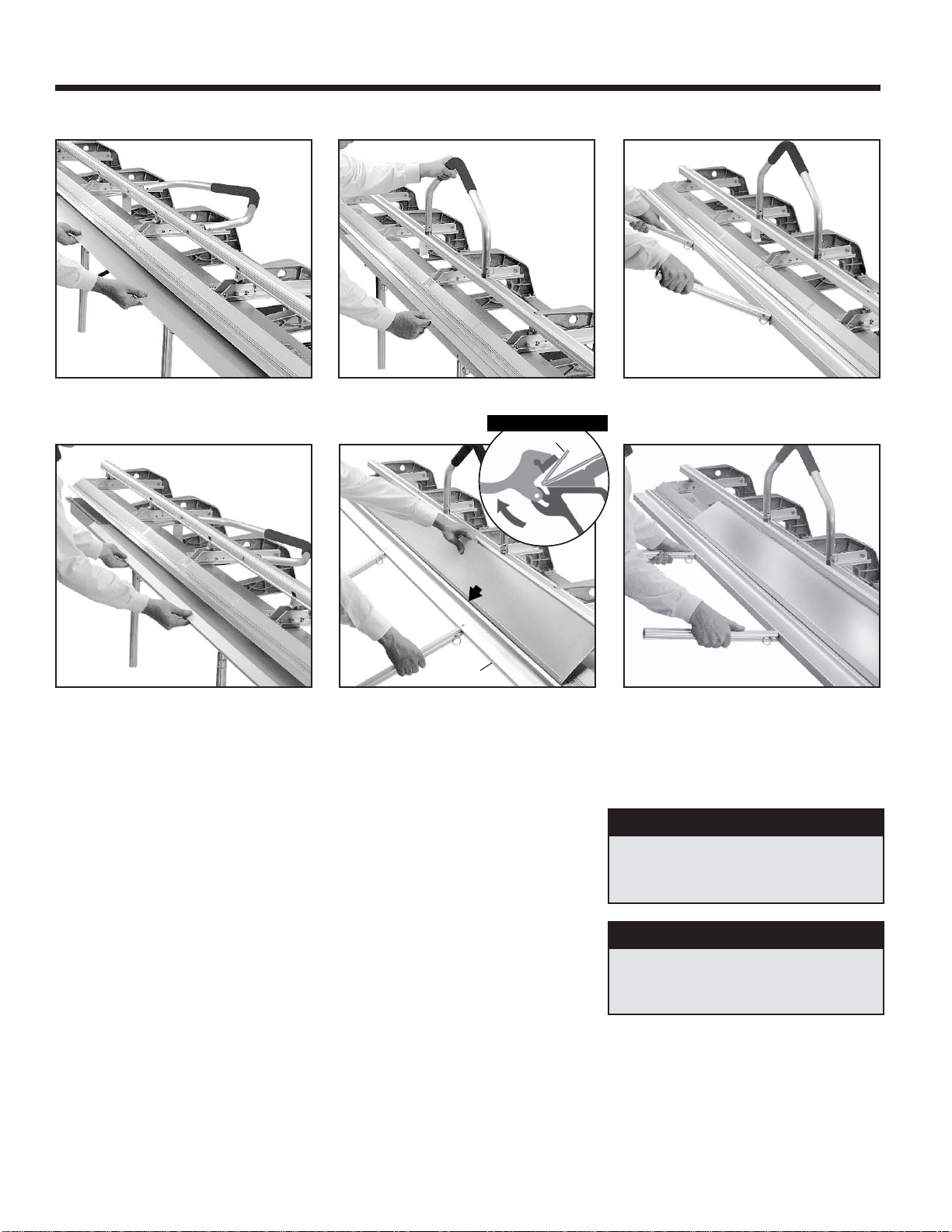
5. For bending, follow the suggested sequence of bends on
pages 8 and 9. For actual bending techniques see “Bending
the Roof Drip Edge” below.
6. Don’t fityour trim parts tootight. Thiswill complicate the joints
where parts overlap. A one inch (1") lap joint is enough to
allow for expansion and contraction.
Trim should be lapped
so that laps are facing away from traffic areas.
7. Try to nail the trim parts on an area that will make the nails
less conspicuous. Fasten at laps. When face nailing, use just
enough nails to secure trim; DO NOT DRIVE NAILS TOO
TIGHT!!
8.
Remember,
when designing shapes you are hanging a cover
over the wood parts, not laminating a skin-tight surface. This
is called “Floating Your Trim”. Allow for irregularities in the
wood because your formed trim shapes are straighter than
the wood trim moldings or boards you are covering.
9. With practice, you’ll learn to overbend or underbend certain
sections to achieve a pressure fit of your trim parts which
will, in turn, require fewer nails and give your job a more
wood-like appearance.
10.Hemming (making a 180°bend on the edge of a sheet) will
give your shape a “Factory Edge Look” and will stiffen the
entire trim piece to help eliminate “oil canning”. See page 6.
1. Measure the total length of the particular trim area to be cov-
ered and divide by the length of your Bender to determine
the number and length of trim pieces needed.
2. Determine the dimensions of each section of the desired trim
shape by measuring that particular profile to be covered. As
an aid, make a pattern out of a 1" strip of coil to get your
exact profile.
3. Transfer the dimensions in Hint #2 to each end of a piece of
trim coil by making a 1/4"slit in the metal with a pair of shears.
These marks now become the bending points and makes
the bending marks visible from either side. On longer lengths
fold the coil over as shown and snip both ends at once. This
saves time and ensures accuracy. The
Tapco Pro-Filer
was
designed to make this time consuming part of your job easier
and more accurate. See page 13.
4. Lock the pre-marked coil blank into the Bender with the cut
marks located directly under the outer edge of the Stainless
Bending Edge. Lock Bender. To cut off the coil with a razor
knife, score the metal against the Stainless Bending Edge.
Now
bend the metal up and push back down by hand until the
exposed
section breaks off. It may require 2 or 3 repetitions.
1. Numbers show the sequence of the bends; thus,
would be the first bend, the second bend, etc.
2."Finish Side Up" indicates that the finished or
exposed side of the trim is to be put into the Bender
FACING UP.
3. "Finish Side Down" indicates that the finished or
exposed side of the trim is to be put into the Bender
FACING DOWN.
4. The symbol *means the bend is to be 180°.
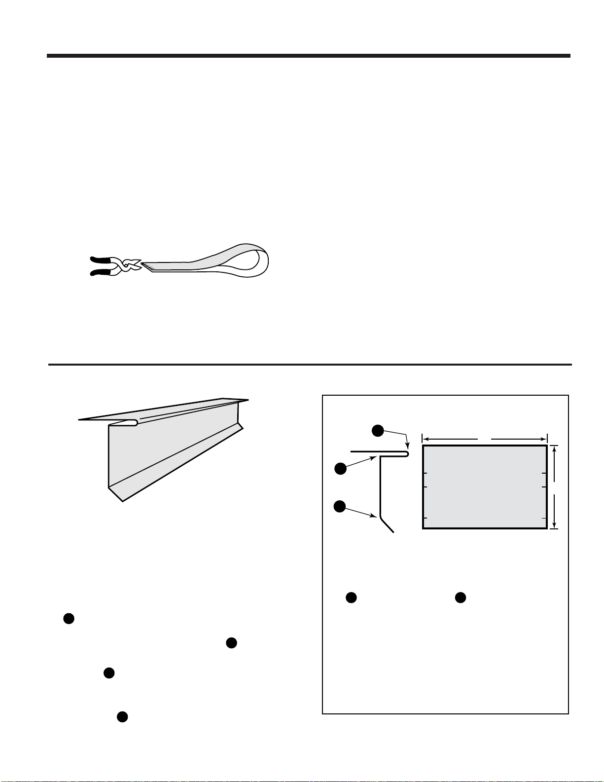
Roof Drip Edge
*
1. This shape is basic to all the other shapes contained in this
manual. Practice this shape before you proceed with the other
trim pieces illustrated on pages 8 and 9.
2. To begin, cut off a piece of coil 43/4inches wide by about 1
foot long (As shown at right.)
3. Mark your coil with a pencil at 2", 23/4"and 41/4"on both ends.
Then snip these marks in about 1/4" (so they will be visible on
both sides of the coil).
4. Put your coil into the Bender with the Finished Side Up. Bend
is the 23/4"mark, so lock the Bender on the mark; then,
bend 90°.
5. Remove the coil from the Bender. Bend will be at the 2"
mark on the coil, so now put the coil into the Bender with the
Finished Side Down. Lock the Bender on this 2" mark. Note
that Bend shows the symbol *which means the bend is to
be 180°. Bend this as far as it will go (about 165°). Then pro-
ceed to hem it in the Bender as shown on Page 12 in “Basic
Hemming and Folding.”
6. Now to Bend put your coil back into the Bender Finished
Side Up and lock on the 41/4"mark. Bend this approximately
45°as shown to complete the shape.
Bending the Roof Drip Edge (General instructions for all examples)

8
*Indicates the bend should be 180°.
Grey color indicates finish side.
1
2
3
Finish
Side
Down
*
Finish
Side
Down
*
Finish
Side
Down
*
Finish
Side
Up
*
EXAMPLES OF COMMON TRIM SHAPES
2. FaciaTrim
4. RakeTrim with Built-in“J”-Channel
3. One Piece Soffit Mitre
5. Soffit and Frieze
1
2
1
2
3
5
4
5
4
3
2
1
6
3
4
1
27
5
Finish
Side
Up
Finish
Side
Up
Finish
Side
Up
Finish
Side
Down
*
Finish
Side
Down
*Finish
Side
Down
Finish
Side
Down
Finish
Side
Up
Finish
Side
Up
Finish
Side
Up
Finish
Side
Down
Finish
Side
Up
Finish
Side
Down
*
Finish
Side
Down
*
Finish
Side
Down
*
Finish
Side
Down
*
Finish
Side
Down
1. All Purpose SillTrim
See notes on Bending the Roof or
Drip Edge “General
Instructions
for All Examples”
on Page 13.
“Finish Side Up”indicates that the exposed or finish side of the trim material is to be placed in the Bender facing up.

9
8. Brick Frieze
9.“F” Channel or Inside Corner
7. OverhangTrim with Built-In Undersill
5
4
2
3
1
3
4
1
2
6
5
10. Window or Door Casing with
Built-in “J” Channel
Finish
Side
Up
*Finish
Side
Up
Finish
Side
Down
Finish
Side
Down
Finish
Side
Down
Finish
Side
Down
Finish
Side
Up
Finish
Side
Up
*
Finish
Side
Down
Finish
Side
Down
*
Finish
Side
Down
Finish
Side
Down
Finish
Side
Down
*
Finish
Side
Up
Finish
Side
Up
6. One Piece Outside Corner
1
2
74
5
6
3
Finish
Side
Down
Finish
Side
Up
Finish
Side
Up
Finish
Side
Up
Finish
Side
Up
Finish
Side
Down
*
Finish
Side
Down
*
Finish
Side
Up
Finish
Side
Down
Finish
Side
Down
Finish
Side
Down
Finish
Side
Up
EXAMPLES OF COMMONTRIM SHAPES
1
2
3
4
5
Finish
Side
Down
*
*Indicates the bend should be 180°.
Grey color indicates finish side.
“Finish Side Up” indicates that the exposed or finish side of the trim material is to be placed in the Bender facing up.
5
4
3
2
1

10
SIDE-WINDER
® (See page 12)
—Saves time by allowing you to
roll out coil directly into the
jaws of your Port-O-Bender.
—Decreases coil damage due to
excessive handling especially
on windy days.
PRO CUT-OFF
® (See page 12)
—Quickly, safely and easily makes
factory quality cuts right on your
Port-O-Bender.
—Saves time and labor in scoring
and cutting off material.
TAPCO ACCESSORIES—
A Necessity forToday’s Professional Sider
PRO-STAND
® (See page 2)
—Solid support and mobility for
your bender on the job site.
—Adjustable heights. Folds up
and detaches in seconds.
E-Z ANGLE
®
Siding Table
(See page 14)
PORT-O-SLITTER
®
Slitting & Rib Forming System
(See page 13)
TAPCO PRO-FILER
® (See page 13)
—Eliminates layout time and need
to snip mark your coil for measuring.
—Simply feed coil in, the Pro-Filer
squares and measures in one opera-
tion, you simply bend.
Other Major Items
PRO-III
®
PORT-O-BENDER
®
“Inside out”
position for coil

11
2
Side-WinderCoil Holder
dispenses
coil directly into the jaws of your
PRO-III.
No need for extra handling
ofcoil stockor separatelayouttable.
Pays off big on windy days.
THE“PRO-III COMPLETE”SAVESTIME, INCREASES PROFITS
The“Pro-III Complete”system includes: Pro-III Port-O-Bender, Pro Cut-Off, Side-Winder,
Tapco Pro-Filer and Pro-Stand. On an average day, they can save you hours on the job site!
8
Pro-III’s
wide mouth opening and large
workingpockets let youform more com-
plex shapes with built-in J-channels to
make your jobs easier, better.
1
Pro-Stand
provides solid support
andtransports your
PRO-III
with all
accessories around the job site.
Saving you time and effort.
4
ProCut-Off
safely cutsthecoil with
afactory edge inseconds. Noneed
toscoreandbreakoffmaterial.Saves
time, effort and reduces scrap.
7
PRO-III’s
patented “moving pivot”
hinge makes bending easier (re-
quires 35% less lifting) and won’t
scuffmaterial,preventingtouch up
work.
Saves 1–2
hours on the
job site in an average day!
•
PRO 2000 Port-O-Bender
•
Pro-Stand
•
Side-Winder
•
Pro Cut-Off
•
Pro-Filer
The
“PRO 2000 Complete” System
Pro Cut-Off
time savings:
PRO-III Hinge
time savings:
Tapco Pro-Filer
time savings:
Pro-Stand
time savings: Side-Winder
time savings:
In Todays Busy
Economy You Have
to be “COMPLETE”
to Compete.
5
Pro-Filer2000
automaticallysquares
material fed into your
PRO-III.
Savestime measuring andsnipping
coil. (See step 6).
PRO-IIIWorking Pockets,
time savings:
6
In making bend after bend,
Pro-Filer
2000
eliminates the need to mea-
sure, mark and snip each piece of
coil, and ensures accuracy.
3
ProCut-Off
cutsyourcoil to length
on the
Side-Winder
in seconds.
Also the
Pro Cut-Off
does double
dutycutting your coilto width. (See
step 4).
15 min. total 35 min. total
55 min. total
90 min. total
100 min.
total 115 min.
Total per Day

12
PORT-O-BENDER
®
ACCESSORIES—
PRO CUT-OFF
™
Quickly, safely and easily
makes factory quality cuts
right on your Port-O-Bender
PRO CUT-OFF Features
•Lightweight aluminum construction built to last.
•Hardened and captured tool steel cutting knives
for safety and durability.
•Pays for itself by reducing scrap and eliminating
knifing damage to costly bending hinges.
•Eliminates use of dangerous utility knives and shears.
•Saves time and labor in scoring and breaking
off material.
PRO CUT-OFF Capacities
•Up to .030 aluminum. All vinyl.
•Up to 28 ga. galvanized steel
•Up to 16 oz. copper
The most
revolutionary tool
since the portable
bender
Just roll out, cut off and in seconds you’re ready for bending!
U.S. & Foreign Pats Pend.
Note: Shear point
remains constant
at 11/2"from your
Bending Edge.➛
➛
➛
➛
To Help You Do It... Faster, Easier, Better
The proper technique is to effortlessly
push your
Pro Cut-Off
through the
material with a smooth, constant motion
from right to left. Do not stop in the mid-
dle
or cut with a back and forth motion.
Make
sure hinge clip is engaged.
1
1
/
2
"
U.S. & Foreign Pats Pend.
Layout coil to measurements along the
length of your
Port-O-Bender
.
2.
Leave
Port-O-Bender
open, use
Pro
Cut-Off
to cut coil to your length and
you're ready to bend!
3.
Draw coil through
Side-Winder
and
into open jaws of your
Port-O-Bender
.
1.
SIDE-WINDER
™
Coil Holder
Keeps the coil at your side—
Where you need it!
Works in tandem with your
Port-O-Bender
and
PRO CUT-OFF
to form
a complete “trim shop”
*When using Tapco
SIDE-WINDER,
PRO CUT-OFF
must be used
to cut off material. Both optional
accessories shown with
PRO III Port-O-Bender
.
SIDE-WINDER Features
•Attaches in seconds to the end of your
PRO III
Port-O-Bender,
standard or heavy duty models.
•Allows you to feed coil directly into the jaws of
your
Port-O-Bender.
Uses your
PRO
CUT-OFF
to
give you factory quality cut offs.*Speeds up
production, decreases waste.
•Helps eliminate damage from handling coil stock,
especially on windy days.
•Holds up to 24"x100' coil (when used with Pro-
Stand). Weighs only 25 lbs.
•New improved versatility! Coil can be drawn out
finished side up or down in seconds depending
on how it’s loaded in the
SIDE-WINDER
.
New and
Improved
New and
Improved
Using your
Pro Cut-Off
(Coil loaded
finished side up)

13
OTHER ACCESSORIES & MAJOR ITEMS
SLITTER CUT-OFF
(optional)
Makes factory quality cross cut offs
to length right on your Port-O-Slitter.
Saves time, increases production.
(24" SLITTER CUT-OFF shown)
Optional Knives
Standard knife set will rib form
and slit. Additional knives are
needed for perforating and mul-
tiple slitting operations. It takes
2 knives to slit and 3 to rib form.
24" Port-O-Slitter Capacities
•Up to .030 soft aluminum
•Up to 28 ga. galvanized steel
•Up to 16 oz. copper
U.S. & Foreign Pats. Pend.
NEW!
NO more
guesswork in
laying out
shapes
PRO-FILER Features
•Automatically squares material fed into your Port-O-Bender
and keeps all your bends parallel.
•Eliminates measuring, marking or snipping on your coil
•Allows exact repeatability of shapes, automates your
production and can save up to 50% of your time
•
PRO-FILER Strips
guide you in making perfect finished
shapes every time. Also functions as a profile
duplicating system. You fashion
PRO-FILER
Strips
to
your desired profile and then simply insert them into the
PRO-FILER
and they guide your bending. Helps
rookies become pros in hours instead of years; helps
pros become more efficient.
TAPCO PRO-FILER
®
Automatic Squaring and Measuring Gauge
Portable precision slitting and rib forming
system for use in the shop or on the job site.
Port-O-Slitter Features
•Slitters come with two sets of cutting knives to make single or
multiple factory quality cuts in aluminum, steel, galvanized
steel, stainless steel, copper, vinyl, clad metals, paper and
some textiles. (Ask your distributor for details.)
•Forms strengthening ribs and perforates most materials for
ventilation purposes.
•Saves 3-4 hours on big jobs.
•Motor kit available in 110v or 220v.
Saves even more time!
•24"
Port-O-Slitter
weighs only 60 lbs.
• MAX Slitters available to slit up to 22 gauge galvanized steel.
(Ask your distributor for details.)
Port-O-Slitter
™
Saves hours on big jobs!
Port-O-Slitter Stand
with
PRO-Coiler
•Feeds coil directly into
Port-O-Slitter,
adjustable
heights.
•
PRO-Coiler
holds up to
24" x 100' coil.
24" model
Port-O-Slitter
with
optional
Port-O-Slitter Stand,
Cut-Off and PRO-Coiler.
Slitter
Cut-Off
24" model
Port-O-Slitter
Siders
Special
Pro-Coiler
Port-O-Slitter
Stand
Attaches to the back of your PRO-III

14
E-Z Angle Capacities
•
Cuts 75
°
up to 10" wide
•
Cuts 72
°
up to 12" wide
•
Cross cuts up to 42" wide
•
Rip cuts up to 48" wide, any length
•
Single handle controls all settings
•
Accepts most 7
1
/
4
"or 8
1
/
4
"full
shoe circular saws
•
Weighs only 68 lbs, folds
to a compact
25"x 72".
U.S. & Foreign
Pats. Pend.
(2x4s not
included)
OTHER ACCESSORIES & MAJOR ITEMS
E-Z ANGLE
®
SidingTable
E-Z Angle SidingTable Features
•Cuts multiple panels simultaneously—safely and accurately.
•Built-in
E-Z
to read protractor and pitch conversion scale for
accurate and reliable angle cuts—One handle controls all.
•Fully captured and locking Saw Plate for accuracy and safety.
•Patent pending design always cuts through center of fixed back
fence eliminating need for adjustments—Saves setup time!
•Unique Saw Track Carriage—slides forward and back to
save you added steps around the table.
•Self-storing reversible 5 foot long Work Support Extension
with
built-in fence—ATapco exclusive!
•Adjustable
E-Z
Material Stop–convenient to use, flips out of
your way when not in use.
•
E-Z Angle
constructed with high-tech anodized alloys for
max-
imum strength, durability and portability.
•Lightweight, affordable saw table for the serious professional,
siding mechanic, carpenter, deck builder and handyman.
E-ZAngle—Easilythebestadditiontoanyworkplace!
(Saw and Stand are Optional. See
page 2 for Pro-Stand information)
TheAffordableMulti-Featured
SidingtableforthePro
NEW!
Retractable
Work
Support with Built-in
Fence! Another Tapco
Exclusive!
Dual purpose wheels
handle the most rugged
of job site terrains then
retract to become
support pads.
“The Siders Helper”. The best all purpose siding and
saw table in the industry
®

15
Leg Tubes
Mounting
Plate
U Clamp
Mounting
Plate
Channel
Leg
Plate
361/2"
361/2"
Center of
Bender
3Set legs onto Bender with leg tubes near drilled
pilot holes. Place “U”
clamps over leg tubes, align
holes
and install sheet metal screws. Drill re-
maining holes through clamps and install screws.
Install screws also in mounting plates as shown.
1Position leg plates into
mounting plate channels,
align holes and install
nuts and bolts provided.
361/2"
361/2"
Drill
Drill
Drill
Drill
U Clamp
Mounting
Plate
Center of Bender
➤
2Invert Bender. From center of Bender,
measure outward along each rail
361/2" and drill one pilot hole in center
of each rail using an 11/64" drill bit.
Installing the Light Duty Folding Legs
OPTIONAL PRO-STAND & LIGHT DUTY LEGS SET UP
Steps (indicated above)
1. Remove all parts from box. Attach 2 x 4 Bracket to Vertical
Support using 1/4-20 x 1 1/2" Hex Bolt and 1/4-20 2-Way Lock
Nut.
2. Slide Vertical Support into EndAssemblies, setting to desired
height, and secure with Faspin (part #10678).
3. Attach Wheel Assembly to End Assembly using 1/4-20 x
2 1/2" Hex Cap Bolt and 1/4-20 Two Way Lock Nut.
4.Fold wheels to pad position (as indicated in diagram) and
stand End Assemblies apart.
5.Attach both Cross Braces by seating pins into center holes in
legs and tightening the “T” Knobs into the top threaded holes
(see Detail A above).
6.Assemble Brake Brackets (see Detail B) securing with hex
nuts. Repeat for other Bracket.
7.From bottom of Bender, align holes in Brake Brackets with
holes in Front and Back Rails of Bender. Insert washer head
screws and tighten Brake Brackets in place.
(*Pre '99 Benders
will need to be drilled)
8
.
TurnBender rightsideup andfit Brake Bracketsinto 2x4 brack-
ets.Align holes in Brackets and insert Faspins. After the Brake
Brackets are installed on the Port-O-Bender, entire unit can
be quickly detached from Pro-Stand by removing Faspins.
Pro-Stand Setup
Instructions
Rail
PRO 2000
PRO III
Only
FRONT OF
BENDER
DETAIL
B
DETAIL
A
Cross Brace
Detail

16
®
Self-Aligning
Starter Strip
Window or Door Casing
with Built-in J-Channel
Windowsill with
Built-in Finish Trim
The
PRO-III
brings
“Profit-O-Bility”
to the job site
Cash in on more profits by selling “custom trim” on every job!
One-piece
Soffit Mitre
F-Channel or
Inside Corner
Plymouth, MI 48170-6010 U.S.A.
Telephone: (734) 451-8272 •Fax: (734) 451-0702
Web site: www.tapcoint.com
TAPCO PRODUCTS COMPANY DISTRIBUTED BY
A DIVISION OFTAPCO INTERNATIONAL
ForYour Records
Model and Serial Number
The Custom Trim ShapesYou Can Make
on the Job Site are Unlimited!
•Self Aligning Starter Strip
•F-Channel or Inside Corner
•Window Sill with Built-in
Finish Trim
•One Piece Soffit Mitre
•Roof or Drip Edge
•Soffit and Frieze
•Utility or Finish Trim
•Facia Trim
•Rake Trim with Built-in J-Channel
•Window or Door Casing with
Built-in J-Channel
•All Types of J-Channel
•One Piece Inside or
Outside Corner
•Custom Shapes
Date and Place Purchased
10816 B
T1016-AG 4/01
Complete the information below and save
with this manual for future reference.
Table of contents
Other Tapco Construction Equipment manuals