Honeywell COMBISAFE 8800 User manual

8800 Loading System MkII
Including 8100 SkyReach Anchor
USER INSTRUCTIONS
0158 - EN 795:2012-E

2
CONTENTS
General 3
Quick Guide 4
Safety instructions 5
Remember 8
Technical data 9
Main Parts 9
Loading System MkII Base 10
Top Column 4.7 11
SkyReach Adaptor 5.9 11
SkyReach Anchor 11
Optional Items 17
Assembly 20
Assembling the Loading System MkII 20
Dismantling 35
Transportation 36
Storage 38
Loading System MkII Base 38
SkyReach Anchor 39
Recommended operating method 40
Single Unit usage 40
Double Unit usage 41
Maintenance 43
Safety check before each use 43
Cleaning 45
Recycling 45
© Combisafe International AB
UI 8800-EN-1932.
Subject to changes.

3
Loading System MkII General
General
The Loading System MkII has been designed to enable the
loading and unloading of equipment from a flatbed truck or
trailer in a safe manner.
The Loading System MkII incorporates a SkyReach Anchor unit
which is connected by a Self-Retracting Lifeline (SRL) to the full
body safety harness worn by the operative.
The SkyReach Anchor is designed to deform, absorb the energy
and reduce the resulting forces, when a fall occurs.
When working at lower heights, the system can be equipped
with the Top Column 4.7. In this configuration the anchor point
is located 4,7 m above ground level. When working at higher
positions the system can be equipped with the SkyReach Adaptor
5.9 which locates the anchor point 5,9 m above ground level. The
combination of Loading System MkII and SkyReach Anchor, is
tested to comply with EN 795:2012 Type E, and is CE-certified
by DEKRA EXAM GmbH, Dinnendahlstraße 9, 44809 Bochum,
Germany, with identification no 0158.
The Loading System MkII can be used on a construction site or
in a loading yard and it can be moved to alternative locations
as needed. To ease transportation and storage, the Loading
System MkII is designed to be flat packed and stackable. When
flat packed the total height of the base is 0,6 m. The SkyReach
Anchor itself can be separated and folded for ease of transport
between locations.
When used for unloading a trailer up to 8 m in length, the
Loading System MkII Single Unit can be used. If unloading a
trailer between 8 and 14 m in length, the Loading System MkII
Double Unit should be used.
Read carefully through this user instruction before use of the
product. In case of questions and uncertainties, please contact
Combisafe for support.

4
General Loading System MkII
Quick Guide

5
Loading System MkII Safety instructions
Safety instructions
The Loading System MkII is intended for the purpose stated
in this user instruction only, any other use is not allowed. The
product is used to protect workers operating at height. If used
incorrectly there is a potential risk of accidents to both the
user and other people in the vicinity. Please read this manual
carefully before use.
• Under no circumstances may the product be used as a makeshift
crane or lifting/lowering device.
• Under no circumstances may any items other than those provided
with the system be used either in replacement or through choice as
this may affect the performance of the product.
• Care should be taken in the transportation of the product between
locations. If any damage is found on any part, the item must be
withdrawn from use, inspected by a trained person and replaced if
required.
• Care should be taken while installing the product and if any damage
occurs or is found in any part, the item should be withdrawn from use,
inspected by a trained person and replaced if required.
• The site location where the Loading System MkII is being used must
have a rescue plan in place, in case of a fall arrest incident.
• The device is intended for use by one person at a time only. Under no
circumstances may multiple persons be attached to the device.
• Where the base is positioned directly onto rough ground, as opposed
to hard standing concrete, sole plates of suitable size and strength
should be placed under the feet of the base to safely transmit and
sustain a load of up to 2,5 N/mm².
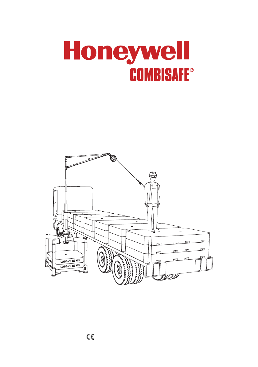
• Do not lift the Loading System MkII unit with SkyReach Anchor by
crane together. Loading System MkII or SkyReach Anchor can be
lifted only separately. When lifting by crane all safety risks must be
eliminated to ensure safety for all personnel on site. Only trained per-
sonnel can operate the crane.
• The SkyReach Anchor is designed to be used within a zero factor fall
arrest system. Make sure that the anchorage is always overhead and
the self-retracting lifeline is taut between the anchorage point and
the worker.
• The maximal vertical deflection of the anchor point that can occur
during service is 0,7 m.
• In case this product is re-sold outside the original country of destina-
tion, it is essential that the reseller provides user instructions in the
language of the country in which the system is to be used.

6
Safety Instructions Loading System MkII
• When referring to any components of the system not produced by
Combisafe, please refer to the specific user guide/manual for that
item.
• The certification of this product is only valid when the prescribed self-
retracting lifeline is used, i.e. Miller Falcon is the only SRL tested and
approved in combination with the Loading System MkII. No other SRL
may be used.
• PFPE that is used together with the Loading System MkII must be
CE-certified and approved in the specific country of usage.
• It is forbidden to use the products stated in this user instruction when
pregnant, suffering from cardiovascular disease, affected by alcohol
or drugs or other health issues that might affect your mental or physi-
cal capacity.
Always check products and equipment before use
Check all component parts of the Loading System MkII before
assembly. Never use damaged or rusty parts, as this can affect
safety. Refer to the check list in the Maintenance chapter which
must be followed prior to use.
Never combine products
It is not recommended to install, combine or interconnect
products other than those supplied by Combisafe. Combisafe
product liability is limited to correctly installed Combisafe
products only.
Always use Personal Fall Protection Equipment
Personal Fall Protection Equipment (PFPE) must always be worn
during assembly and dismantling when a risk of falling exists,
see Figure 1. This also applies to work carried out from MEWPs
(Mobile Elevating Working Platforms).
Figure 1. Personal Fall Protection Equipment

7
Loading System MkII Safety instructions
Fall clearance
Note that it is essential to verify that adequate free height exists
to the closest underlying object, please see Figure 2 below.
A
A+B
A+B
C
Figure 2. Explanation of fall clearance.
A: 0,7 [m] Maximum vertical deflection of the SkyReach
Anchor Point
B: X Braking distance of the SRL. Please refer to the
manufacturer´s user instructions for specific values.
C: 1 [m] Safety distance.
Total required fall clearance = A+B+C

8
Safety instructions Loading System MkII
Periodic inspection/inspection after a fall
To ensure the function and safety of the components, a safety
inspection of the SkyReach Anchor, the attachments and the
PFPE, needs to be done by a competent person at least once
every 12 months. The inspections must be documented into a
component record.
If an accident has occurred, e.g. a person has fallen, the items
must be immediately withdrawn from use and inspected by a
competent person according to the manufacturer´s safety check.
Please contact Combisafe for more information regarding
inspections and associated documentation.
NOTE
The SkyReach Anchor is designed to deform if a fall occurs, to
absorb the energy and reduce the arising forces. When tested,
the maximum vertical deflection of the anchor point is 0,7 m.
Remember
• Plan fall prevention at an early stage, this will benefit everyone.
• Use only safety-checked products.
• Restrict access below and around the installation and working area to
prevent injury to others from any fall hazard.
• Use tools designed for the type of work to be carried out.
• Keep the installation area in order.
• A safe workplace is a good workplace.
• Many fall accidents occur from a low height.
• Parts might be slippery when wet, be cautious when handling.

9
Loading System MkII Technical data
Technical data
Main Parts
Figure 3. SkyReach Anchor in assembled mode and folded mode.
Item Art no. Designation Weight
18100 Loading System MkII Base 250 kg
211468 Top Column 4.7 25 kg
38801 SkyReach Adaptor 5.9 27 kg
48100 SkyReach Anchor 25 kg

10
Technical data Loading System MkII
Loading System MkII Base
Material: Painted steel
Total weight: 250 kg
Height: 1,5 m
Width: 1,6 m
Depth: 1,4 m
Figure 4. Loading System MkII Base.
Item Art no. Designation Weight
1100413 Combistrap, 1 m (2 pcs) 0,1 kg/pc
211468 Top Frame 72 kg
311431 Corner Post (4 pcs) 10 kg/pc
411432 Bottom Frame 125 kg
511518 Foot (4 pcs) 2 kg/pc

11
Loading System MkII Technical Data
Top Column 4.7
When working at lower heights the Top Column 4.7 locates the
anchor point at 4,7 m above ground level. The Top Column 4.7 will
fit into the Base when the Base is packed and therefore takes up
no extra space when storing the item.
Material: Hot-dip galvanised/painted steel
Weight: 25 kg
Height: 1,2 m
SkyReach Adaptor 5.9
When a greater working height is required than the Top Column
4.7 provides, the SkyReach Adaptor 5.9 will give a total height of
5,9 m from the ground to the anchor point.
Material: Hot-dip galvanised/painted steel
Weight: 27 kg
Height: 2,4 m
SkyReach Anchor
The SkyReach Anchor is designed to be a lightweight product
and is easily foldable for moving and configured to be space-
saving when transporting or storing the item, see Figure 5. To
secure both positions (assembled mode and folded mode) the
attached Lock Pin is used.
For lifting SkyReach Anchor by crane there are 2 lifting eyes. For
lifting use 2 incorporated slings, each connected to one lifting
eye (slings code 100690).
Material: Hot-dip galvanised/painted steel
Weight: 25 kg
Height: 3,1 m
Assembled width: 2,0 m
Packed width: 0,2 m

12
Technical Data Loading System MkII
Figure 5. The SkyReach Anchor in assembled and folded mode.
SkyReach Anchor Labels and Markings
The Figure 6 below shows all the labels and markings of the
SkyReach Anchor. The following figures (Figure 7, Figure 8 and
Figure 9) are showing these important elements.

13
Loading System MkII Technical Data
Figure 6. Labels and markings on the SkyReach Anchor.
1. ID Plate
2. Reflective Tape
3. Anti Slip Grip Tape
4. Insertion Marking Label
5. 5 x Reflective Tape
6. Combisafe Label
7. Anti Slip Grip Tape
8. Product Information Label

14
Technical Data Loading System MkII
Figure 7. A close-up of the ID Plate which includes the serial
number.
www.combisafe.com
0158 EN 795:2012
SKYREACH Anchor #8100
#8200
Type B
#8500/8501
Type B
#8800
Type E
#8100
TP TC
019/2011
Combisafe International AB
Tallbacksgaten 16,19572 Rosersberg,
Sweden
© Combisafe International AB 100583 -1931
Figure 8. Detailed view of the Product Information Label
1. Manufacturer.
2. Name of the product.
3. Identification number of the notified body; DEKRA EXAM
GmbH, responsible for CE production quality control.
4. Compliance with EN 795:2012.
5. Pictogram: Read user instruction before use.
6. Description of usage.
7. Product combination with different attachments.
MAX5mm
MAX5mm
Figure 9. A close-up of the Insertion Marking Label, which shows
accepted tolerances when inserting the SkyReach Anchor into its
attachment.
123456

15
Loading System MkII Technical Data
Personal Fall Protection Equipment
To create a complete system to protect the operative when
working at height, the Loading System MkII including SkyReach
Anchor needs to be equipped with Personal Fall Protection
Equipment (PFPE). Figure 10 shows an example of how to equip
the SkyReach Anchor with recommended PFPE. All PFPE that is
used must be certified and approved in the specific country of
use.
The following PFPE is approved to be used together with the
SkyReach Anchor and the Loading System MkII:
SRL
Fall Arrest Block certified to EN 360.
Only the Miller Falcon 6,2 m, or the Miller Falcon 10 m when
a Double Unit is used, has been tested and approved in
combination with the Loading System MkII and SkyReach
Anchor, and thus the only SRL (Self Retracting Lifeline) that
will enable the system to be CE certified. Use of other SRL will
invalidate the CE certification.
Harness
Full body harnesses certified to EN 361
Lanyard
Non shock absorbing lanyards certified to EN 354
Can be used separately or in combination with EN 355 certified
lanyard, or with a max length of 0,6 m in combination with the
Falcon Fall Arrest Block.
Lanyard
Shock absorbing lanyards certified to EN 355
Can be used separately or in combination with an EN 354
certified lanyard. Must NOT be combined with the Falcon Fall
Arrest Block.

16
Technical Data Loading System MkII
2
3
1
4
Figure 10. The figure shows the SkyReach Anchor equipped with
recommended PFPE.
Item Art no. Designation Weight
18100 SkyReach Anchor 25 kg
2 - Full body harness certified to EN 361 -
3CM1002889 Miller extra webbing, 0.3 m 0,2 kg
4CM1011729 Miller Falcon SRL, 6.2 m 4 kg

17
Loading System MkII Technical Data
Optional Items
The following items are not delivered as standard together with
the Loading System MkII but can be ordered separately if required,
please see Figure 11 for visual clarification of the items.
Precast Kentledge (Art. 11655)
This precast concrete block is one out of three possible ballast
options (2 concrete blocks), and can be ordered from Combisafe.
Please see the following chapter Ballast for more information.
Material: Concrete
Weight: 800 kg
Height: 0,2 m
Width: 1,4 m
Depth: 1,4 m
Formwork Support (Art. 11446)
To use the second ballast option, the Loading System MkII Base
needs to be equipped with 8 pcs of the Formwork Support. These
steel channel sections with timber inlays will give the support
needed to the side boards when the base is filled with gravel or
concrete.
Material: Painted steel/wood
Weight: 11 kg
Length: 1,4 m
SkyReach Reach Hook (Art. 11530)
The Reach Hook is useful to guide the SkyReach Anchor into
the Top Column 4.7/SkyReach Adaptor 5.9 when the anchor is
lifted and lowered by crane. It has a telescopic shaft which is
extendable from 1,2 to 2,7 m.
Material: Aluminum/Hot dip galvanised steel
Weight: 1,0 kg
Length: 1,2 – 2,7 m

18
Technical Data Loading System MkII
Figure 11. Optional items.
Item Part no. Designation Weight
111655 Precast Kentledge (2 pcs needed) 800 kg/pc
211446 Formwork Support (8 pcs needed) 11 kg/pc
311530 SkyReach Reach Hook 1,5 kg

19
Loading System MkII Technical data
Ballast
The Loading System MkII Base needs to be loaded with a
minimum 1500 kg of suitable ballast to keep it stable and meet
the requirements in the standard. The ballast can be applied in
three different ways, which are presented below. Further details
on how to perform the ballast loading procedures are described
in the Assembly chapter.
• Precast Kentledge
The Precast Kentledge is a 800 kg concrete block designed to fit
into the Loading System MkII Base. Using two units of the Precast
Kentledge is enough to achieve the weight requirement and provide
margin in case of wear of the blocks. These should be ordered as an
option as they are not included as a standard. It is recommended to
use these blocks due to its precise weight and safe positioning.
• Concrete box cast on site or gravel box
For this option, the Formwork Supports should be ordered, as they are
not included in Loading System MkII as standard. With the Formwork
Supports mounted, a plywood box inside the Loading System MkII
Base will make it possible to cast concrete into the box directly on
site. It is also possible to fill the plywood box with gravel.
• Other ballast option
In case none of the standard solutions noted above is used, it is
possible to use other ballast types. In this case it is the customer’s
responsibility to ensure that the ballast:
• Has a weight no less than 1500kg,
• Is distributed centrally on the Bottom Frame of the Loading Sys-
tem MkII Base,
• Has no possibility of movement.

20
Assembly Loading System MkII
Assembly
Assembling the Loading System MkII
The following information and illustrations are a step by step
guide on how to rig a Loading System MkII including a SkyReach
Anchor unit successfully. The Loading System MkII can be used
with any of the three ballast options described. Please refer to the
appropriate instruction pertaining to the actual case.
Before attempting to rig a Loading System MkII unit, please make
sure you have the following tools:
• Hammer, 22 mm spanner or adjustable spanner for adjusting the feet
• Spirit level.
• Crane for installation of the SkyReach unit.
• Fork lift truck, or equivalent, for lifting the component parts.
Installation instructions for Loading System MkII
1. Make sure that the ground, where the Loading System MkII
is placed, is relatively flat. The Loading System MkII Base has
adjustable feet which are designed to adjust within a 5 degree
inclination. Use a fork lift truck to handle the Bottom Frame,
place the forks underneath the horizontal tubes into the fork
guiding profiles prior to lifting, see Figure 12. Place the Bot-
tom Frame on the ground. Use a spirit level to make sure that
the Bottom Frame is level. If not, rotate the feet by hand or
use a 22 mm spanner or a hammer to strike on the Adjust-
ing Bar to adjust the feet until the Bottom Frame is level, see
Figure 13.
Table of contents
Other Honeywell Construction Equipment manuals