HIAB J14S User manual

HIAB J14S J24S
Operator's Manual GB
This operator ’ s manual is an Original Instruction and applies for loaders from serial number:
BJ14S0000001, BJ24S0000001
2020-07

Congratulations with your new loader!
You are now the owner of a quality product from Cargotec, built to the highest standards of safety
and quality.
The aim of this manual is to help you handle your loader safely and with full satisfaction.
Please read the complete manual. It provides detailed information about the loader, control system
and the practical management and maintenance of the loader.
We advise you to read it carefully and familiarize yourself with your loader before you start to use it.
Help us to improve this manual. Please send your comments and suggestions to
This manual includes interactive contents.
Download the 'Hiab AR+ App' for the interactive content in this manual. Look for the AR+
symbol. Use your device to scan the image next to the symbol.
The interactive contents in the Hiab AR+ App will display suggestions to make the loader
operation easier for you to understand. However, note that some of the content included in the
'Hiab AR+ App' may differ from the actual configuration of your loader and is subject to
updates and changes from Hiab without prior notice.

Table of Contents
1. Introduction ......................................................................................... 5
1.1. This Operator's Manual is intended for operators of this loader. ................... 5
1.1.1. Cleanliness certificate ........................................................ 6
1.1.2. Description of Hiab J14S and J24S ......................................... 7
1.2. Indications in the Operator’s Manual .................................................. 7
1.3. Identification of the utility loader ....................................................... 9
2. Structure and parts of the loader ............................................................... 10
2.1. Main groups ............................................................................ 10
2.2. Loader base with column and slewing system ..................................... 10
2.3. Boom system and add-on lifting accessories ...................................... 10
2.4. LHV Load Holding Valves (option) ................................................... 11
2.5. Stabiliser system ...................................................................... 12
2.6. Operating system - hydraulic components ......................................... 12
2.7. Buttons on the control panel ......................................................... 13
2.8. Premium high seat .................................................................... 14
2.9. Main control valve ..................................................................... 14
2.10. Stabiliser control valve .............................................................. 14
3. Safety precautions and warnings .............................................................. 15
3.1. Operating conditions .................................................................. 15
3.2. Wind speeds ........................................................................... 16
3.3. Signs on the loader .................................................................... 17
3.4. Maximum load ......................................................................... 17
3.5. Signals when using a loader [AR+] .................................................. 19
3.6. Use of the loader ...................................................................... 22
3.6.1. Use of lifting equipment .................................................... 27
4. Manual control system .......................................................................... 30
4.1. Operation from the high seat ......................................................... 30
4.2. Extension boom control system ...................................................... 32
5. Starting loader operation ........................................................................ 33
5.1. Starting operations .................................................................... 33
5.2. Extend stabiliser extensions and set stabiliser legs ............................... 33
5.2.1. Stabiliser system and ground conditions ................................. 34
6. During operation ................................................................................. 36
6.1. Operate the loader .................................................................... 36
7. Ending loader operation ........................................................................ 38
7.1. Placing the stabiliser system in transport position ................................. 38
7.2. Operate the boom system into transport position .................................. 39
7.3. Transport Warning Interface (TWI) .................................................. 41
7.4. Emergency operation of the dump valve ........................................... 42
7.5. Emergency operation of the boom extension ...................................... 43
8. Maintenance and Service ....................................................................... 44
8.1. Warranty ................................................................................ 44
8.2. Service .................................................................................. 44
8.3. Follow the maintenance instructions! ............................................... 45
8.3.1. Daily inspection .............................................................. 46
8.3.2. Weekly inspection and maintenance ...................................... 47
8.3.3. Monthly inspection and maintenance ..................................... 47
HIAB J14S J24S 3

8.3.4. Twice a year maintenance ................................................. 48
8.3.5. Annual maintenance ........................................................ 48
8.4. Lubrication .............................................................................. 49
8.4.1. Lubrication ................................................................... 50
8.4.2. Lubrication of the upper column bearing ................................. 51
8.4.3. Clean and grease the spring cups. ........................................ 51
8.5. Adjust the lateral clearance of the boom and/or hydraulic extension ............ 51
8.6. Adjust the chain in the telescope .................................................... 52
8.7. Hydraulics .............................................................................. 53
8.7.1. Loader base: checking the oil level/oil change ........................... 53
8.7.2. Bleeding air from the hydraulic system ................................... 53
8.7.3. Replacing the cartridge in return oil filter ................................. 54
8.7.4. Replacing the cartridge in high pressure filter ........................... 55
8.7.5. Checking the oil tank level ................................................. 56
8.7.6. Changing the hydraulic oil .................................................. 56
8.8. Troubleshooting ........................................................................ 58
8.8.1. Faults in the loader .......................................................... 58
8.8.2. Troubleshooting of the boom extension control .......................... 59
9. Technical Data ................................................................................... 60
9.1. Load plate table ........................................................................ 60
10. Decommissioning .............................................................................. 61
10.1. Decommissioning a loader .......................................................... 61
4 HIAB J14S J24S
1. Introduction
1.1. This Operator's Manual is intended for operators of this
loader.
The aim of this manual is to help you handle your loader
safely and with full satisfaction. Please read the complete
manual. It provides detailed information about the loader,
control system and the practical management and
maintenance of the loader. We advise you to read it
carefully and familiarize yourself with your loader before
you start to use it.
DANGER
Study these instructions carefully
If you do not study the complete Operator’s Manual for your loader carefully, it
could lead to fatal accidents or serious damage.
Therefore you should:
• Study the entire Operator’s Manual carefully.
• Study the operating manuals for other add-on equipment, if fitted.
• Use the loader only after having done so.
• Follow the directions for use, operation and maintenance of the loader and add
on equipment exactly.
• Store the Operator’s Manual for your type of loader, the Technical Data and
manuals from the Installer, together with this Operator's manual.
This manual describes:
• Operation
• Safety precautions and warnings
• The loader control system
• Maintenance and troubleshooting
Enclosed to this manual the Installer will provide:
• Technical Data for your loader
• Technical Data and manuals for add on equipment if fitted
Introduction
HIAB J14S J24S 5
Therefore you should:
• Study the entire Operator’s Manual carefully.
• Study the operating manuals for other add-on equipment,
if fitted.
• Use the loader only after having done so.
• Follow the directions for use, operation and maintenance
of the loader and add on equipment exactly.
• Store the Technical Data and manuals from the Installer,
together with this Operator's manual.
NOTE
The manufacturer reserves the right to change specifications, equipment,
operating instructions and maintenance instructions without prior notice.
Study these instructions carefully
DANGER
If you do not study the complete Operator’s Manual for your loader carefully, it
could lead to fatal accidents or serious damage.
1.1.1. Cleanliness certificate
All Hiab equipment has been tested and certified at the
factory according to the Hiab Standard C250.52 that
defines the Cleanliness Requirements for Hydraulic
Systems. This means that they fulfil the cleanliness class
20/18/14 measured by the ISO 4406 standard.
All hydraulic functions have been individually tested and
fully comply with the defined requirements.
Introduction
6 HIAB J14S J24S
NOTE
Hiab shall at all times have the right to:
• install, maintain and dismantle remote diagnostics tools or similar sensor-based
connectivity capabilities (“Connectivity”) in and from the Equipment; and
• access, send, receive, collect, store and use any and all information and data
gathered through the Connectivity, including but not limited to, information
concerning efficiency, availability, downtime, operation, operating environment,
movement, condition, logon, location and similar information relating to the
Equipment (the “Information”). Such Information may be used for optimizing the
Equipment, or any related equipment or services as well as for Hiab's internal
business and/or operating purposes. Hiab shall be responsible for complying
with applicable laws and regulations related to such Information.
The customer/user shall not in any way remove, disable, or interfere with the
Connectivity or the Information. Any intellectual property rights or other right and
title in and to the Connectivity features and the Information and all their further
developments shall at all times be and remain the exclusive property of Hiab.
1.1.2. Description of Hiab J14S and J24S
The Hiab J14S and J24S utility loaders manufactured by Hiab are designed for several truck
mounted applications where grapple type attachment is to be utilized. Typical applications would
include railroad Hi-Rail trucks or grapple trucks for waste and recycling material handling.
Installation can be done either as rear mounted or behind the cab. Utility loaders are not intended
for hook operation .
The Hiab J14S and J24S are available for various applications in different boom versions and with
wide range of options and accessories
On the serial number plate, you can find information on the loader type and on the manufacturer.
NOTE
The exact technical information for your loader is shown in "Technical Data".
1.2. Indications in the Operator’s Manual
What must you do and not do?
The following indications are used in the Operator’s Manual:
DANGER
Danger to life for yourself or to bystanders.
Follow the instructions carefully!
Introduction
HIAB J14S J24S 7

WARNING
Danger of injury to yourself or to bystanders, or danger of serious damage to the
loader or other objects.
Follow the instructions carefully.
CAUTION
Hazard for the loader or loader components. Follow the instructions carefully.
Important:
If actions are numbered
1. Do this
2. Do that
3. ......
4. .....
5. .....
you should carry them out in numerical order!
NOTE
Extra information that can prevent problems.
TIP
Tip to make the work easier to carry out.
Symbol for reference to a component in an illustration.
(1) Refers to a component in an illustration.
[option]: Indication for parts that are not-standard for the
loader, but are an option. Not all [option] are available for
your loader.
DANGER
Only persons with the requisite knowledge and experience with loaders may use
the loader. Never operate the loader when you are sick, tired, under the influence
of medicines, alcohol or other drugs.
Introduction
8 HIAB J14S J24S
• Take the delivery instructions from your HIAB Service workshop, or receive instruction from an
experienced person from your own company. Only then should you operate your loader.
• Ensure that you comply with the statutory requirements of the country in which you use the
loader (for example, certificate, obligatory safety-helmet).
DANGER
• Carry out yourself only the service and
maintenance work you have the requisite
knowledge and experience of.
• All other maintenance work may only be
carried out by a HIAB service workshop.
• Ensure that every defect is rectified
immediately, according to the instructions.
• Follow the instructions exactly!
• All other work to rectify faults must be
performed by personnel in a HIAB service
workshop!
WARNING
• Never clean the electronic system, plastic components, signs or bearings with a
high-pressure jet cleaner. It could cause damage.
• Never expose the electronic system to high electrical voltages. This could
damage the control system.
• Never immerse the controller in water or other liquid. This will make the
controller unusable.
If your loader is equipped with add-on lifting equipment (hoist, rotator, etc.):
• The operation of the loader with add-on lifting equipment can differ from the
operation as described in this manual.
• You should therefore study the Operating Manual for the add-on equipment
carefully, before you use the loader.
• Take particular note when placing the loader in to or out of transport position.
1.3. Identification of the utility loader
Description and identification of the utility loader:
Mark: ...................
Type: ...................
Serial number: ............................
Manufact. year: ............................
Type: ..................................
Serial number: .................................
Manufact. year: .....................
Mark: .....................
Introduction
HIAB J14S J24S 9
2. Structure and parts of the loader
2.1. Main groups
This HIAB loader consists of the following main groups:
• Loader base with column and slewing system
• Stabiliser system
• Boom system
• Operating system - hydraulic components
Some accessories can be fitted depending on your loader configuration:
• Add-on lifting accessories [option]
• Separate lifting accessories [option]
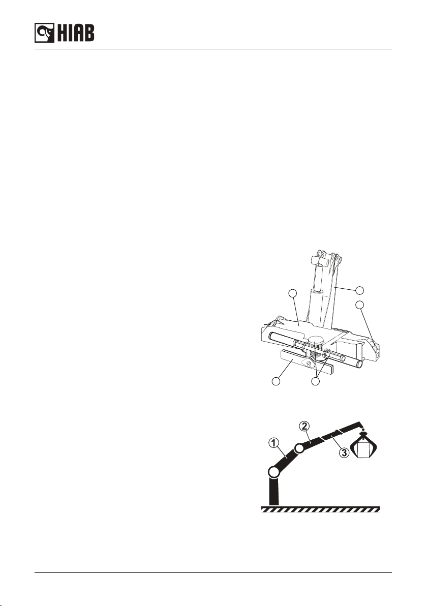
2.2. Loader base with column and slewing system
The loader base, column and the slewing system
consist of the following components:
(1) Loader base.
(2) Stabiliser beams.
(3) Three-point bridge.
(4) Column.
(5) Rack and pinion slewing system.
2.3. Boom system and add-on lifting accessories
The boom system consists of the following
components:
(1) 1st boom
(2) 2nd boom
(3) Hydraulic extensions, the length of the hydraulic
extension depends on the type of loader.
Add-on lifting accessory is placed between the boom tip
and the load.
1
2
3
4
5
Structure and parts of the loader
10 HIAB J14S J24S

2.4. LHV Load Holding Valves (option)
Cylinders can be optionally equipped with Load Holding Valves (LHV) as a safety device. After a
loader movement they hold the loader in position, also in the unlikely event of a burst hose.
If there is a leak or a component fractures, such as a pipe, hose or a coupling, the LHV will stop the
booms from collapsing down, even when the hydraulic system is switched off and you operate a
particular loader function.
To operate a hydraulic cylinder equipped with a LHV, an opening pressure is required.
DANGER
Overloading could result of damage to the loader or in the worst case, personal
injury or death.
Never increase a hanging load, since that may cause a Load Holding Valve to
open and/or the vehicle to turn over.
NOTE
The extra weight of the lifting accessories has to be added to the load. Thus, with
lifting accessories the load you can lift is less heavy.
Load Holding Valves are not mandatory. The installation is based on the
application and regulatory requirements.
Structure and parts of the loader
HIAB J14S J24S 11

2.5. Stabiliser system
Every loader is equipped with two stabiliser extensions and
two stabiliser legs. Auxiliary stabiliser systems may be
needed for heavy loaders.
(1) Stabiliser beam. The stabiliser beam is a part of the
loader base.
(2) Stabiliser extensions.
(3) Stabiliser locking device.
(4) Stabiliser legs.
2.6. Operating system - hydraulic components
The operating system consists of the following hydraulic components:
• oil tank
• hydraulic pump
• oil cooler [option on some loaders]
• main control valve
• stabiliser control valve
• hydraulic hoses and lines
• actuators:
- first boom cylinder
- second boom cylinder
- extension cylinder/s
- slewing cylinders
• return filter/oil tank
• pressure filter
1
2
3
3
3
4
Structure and parts of the loader
12 HIAB J14S J24S

2.7. Buttons on the control panel
The loader and the stabiliser system can be operated from the high seat.
(1) Stabiliser leg, left
(2) Stabiliser leg, right
(3) Stabiliser extension out/in
(4) Console or optional function
(5) Optional function
(6) Lights
(7) Activation of the extension control
(8) Seat heat [option]
(9) Button to be used together with (1), (2), (3)
(10) Optional button
(11) Emergency STOP button
DANGER
Take care not to put your foot on the pedals when entering in the high seat.
Unintentional loader movements can occur.
Structure and parts of the loader
HIAB J14S J24S 13
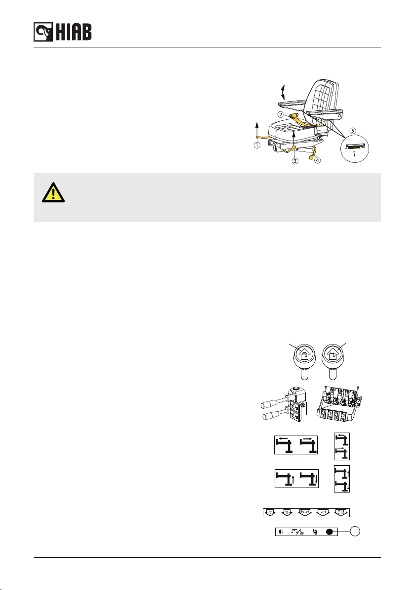
2.8. Premium high seat
(1) Handle to adjust seat forward/backward
(2) Seat belt (not mandatory feature)
(3) Handle to adjust height of the seat
(4) Locking device for seat tilting
(5) Handle to adjust armrest
DANGER
Take care not to put your foot on the pedals when entering in the high seat.
Unintentional loader movements can occur.
2.9. Main control valve
Near each lever there is a sticker with a symbol. The symbol illustrates the function of the lever.
Always operate the lever according to the symbol sign.
The speed of a function corresponds to the extent of the lever movement, regardless of the load
and other functions, as long as the oil flow is sufficient. When the oil flow is insufficient, one or more
functions might reduce their speed.
2.10. Stabiliser control valve
The loader is equipped with a stabiliser control valve. The
valve can be operated with the levers on the valve and
from the high seat.
There are several types of stabiliser control valves. Always
operate the lever according to the function on the symbol
sign.
The symbol is shown either on the lever knob or on a
separate sign placed vertical/horizontal next to the lever.
•Stabiliser extension (1) out/in
•Stabiliser leg (2) upward/downward
The stop button affects the oil supply to this valve.
Operate the stabiliser extensions and stabiliser legs.
From the high seat:
Press and hold the button (3) at the same time.
➀
➁
➀➁
3
Structure and parts of the loader
14 HIAB J14S J24S

3. Safety precautions and warnings
3.1. Operating conditions
You may only use the loader under the following conditions:
• In the open air, or in spaces with sufficient ventilation.
• With a mean wind velocity less than 13.3 m/sec (approx. 29.7 mph).
DANGER
• If you use the loader in a confined space you could suffocate from the exhaust
gases from the vehicle.
•Never use the loader at temperatures below -40° C (-40 °F), as the steel's
properties deteriorate below this temperature.
WARNING
• If the temperature is below 0 °C (32 °F) we
recommend you to wait a few minutes
before you operate the levers
• When starting in cold weather, the wear on
the hydraulic system is greater than at
normal working temperatures.
To minimise wear, the loader should be started as follows:
• Engage the power take-off at low rpm.
• Allow the system to idle for a few minutes.
• Fixed pump:
Operate the stabiliser leg up for one minute in order to warm up the oil.
• Variable pump:
Operate stabiliser legs up and down for one minute, in order to warm up the oil.
Safety precautions and warnings
HIAB J14S J24S 15

3.2. Wind speeds
Wind speed averaged over 10 minutes at a height of 32 ft 9.7 in
Wind
Force
Above flat ground Characteristics
mph Wind type
0 0.0 - 0.4 Calm Calm, smoke rises vertically or nearly
vertically
1
2
0.5 - 3.4
3.5 - 7.4
Slight breeze Wind direction recognisable from smoke
plumes, the wind begins to be noticeable on
the face; leaves begin to rustle and weather
vanes can start to move.
3
4
7.5 - 12.0
12.1 - 18.0
Moderate wind Leaves and twigs in continuous movement,
small branches begin to move. Dust and
paper begin to move over the ground.
5 18.1 - 24.0
Fairly strong
wind
Small leaved branches make swaying
movements; crested waves form on lakes
and canals.
6 24.1 - 31.0
Strong wind Large branches move; you can hear the
wind whistling in telephone wires; umbrellas
can only be held with difficulty.
7 31.1 - 38.0 Severe wind Entire trees move; the wind causes difficulty
when you walk into it.
8 38.1 - 46.0 Stormy wind Twigs break off, walking is difficult.
9 46.1 - 55.0
Storm Causes superficial damage to buildings
(chimney pots, roof-tiles, and TV antennae
are blown off).
10 55.1 - 64.0 Severe storm Uprooted trees; considerable damage to
buildings etc. (occurs infrequently on land).
11 64.1 - 73.0 Very severe
storm
Causes extensive damage (occurs very infre
quently on land).
12 > 73.0 Hurricane
Safety precautions and warnings
16 HIAB J14S J24S
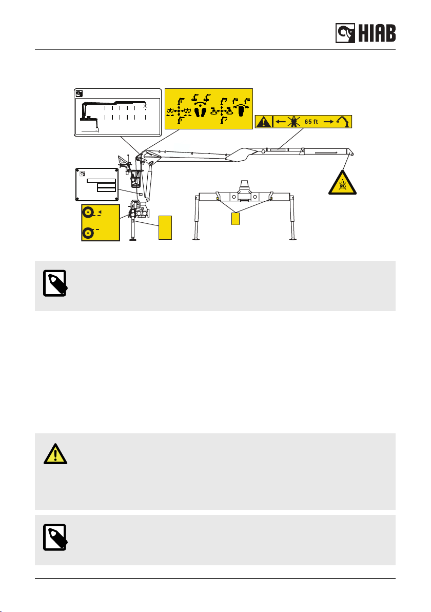
3.3. Signs on the loader
SAE 80W/90
MAX
MIN
T YT T STÄ Ä Ä Ä
P FYLLNINGÅ
FILLING
EINF LLUNGÜ
REMPLISSAGE
Cargotec Poland Sp.z.o.o.
ul.Stalowa 2 73-102 STARGARD POLAND
TYPE
SERIAL NO
MANUF. YEAR
xxx-xxxx
xxxxxxxxxx
MAX
X X X X X X,X
Ib
XXXX
XXXXXXXXXXXXXXXXXXXX
XXXXXXX XXXX XX
ft
NOTE
The signs may vary depending on the country. Always make sure that you comply
with the statutory requirements of the country in which you use the loader.
3.4. Maximum load
Lifting capacity
Your loader has a certain lifting capacity, expressed in kNm or tm. This lifting capacity is also
known as the load moment. The lifting capacity is: the payload multiplied by the outreach in metres
that the loader can operate at different positions. The lifting capacity of your loader determines the
maximum load your loader may lift within its working zone. However take careful note; the greater
the operating radius of the loader, the lower the lifting capacity will be because of the weight of the
boom system itself. The load plate and the load diagram on your loader show the maximum loads
you may lift in the operating reach of your loader.
DANGER
Overloading could result of damage to the loader or in the worst case, personal
injury or death.
Never increase a hanging load, since that may cause a Load Holding Valve to
open and/or the vehicle to turn over.
NOTE
The extra weight of the lifting accessories has to be added to the load. Thus, with
lifting accessories the load you can lift is less heavy.
Safety precautions and warnings
HIAB J14S J24S 17

NOTE
Load Holding Valves are not mandatory, the installation is based on the application
and regulatory requirements.
Load plate
On the plate is the maximum weight that you may lift at a
given reach, with the 1st boom in the optimum position. In
chapter Technical Data in this manual you will find these
values for your loader.
DANGER
Never exceed the maximum weight on the load plate.
Load diagram
The load diagram shows the maximum load your loader
may lift in the entire working zone.
The load curves show the maximum load that may be lifted
at a given reach and height. For a given maximum load, the
possible working zone is to the left of the load curve. The
lifting capacity for some loaders is limited in the high lifting
area.
WARNING
Care must be taken when handling loads in the high lifting area, so the load/tool
does not come into contact with the boom system.
MAX
ft
Ib
Safety precautions and warnings
18 HIAB J14S J24S

3.5. Signals when using a loader [AR+]
DANGER
• If it is not possible to see the load and the entire working area clearly the loader
operator is obliged to follow the instructions and signals given by a qualified
person qualified.
• The country-specific regulations for loader operator signals are to be used.
Signals in this manual give a number of standard signals that can be used.
Lift
Raised arm and index finger raised. Circular motion with
hand.
Lower
Arm pointing downwards and index finger down. Circular
motion with hand.
Stop all loader movements / Hold the load in position
Raise the open hand, with the palm clearly visible, and arm
at shoulder height.
Keep the hand still.
Safety precautions and warnings
HIAB J14S J24S 19

Emergency stop for all movements by the loader
Raise the hands and the arms to an oblique angle.
Very short movement
Place the hands a very short distance apart, with the palms
facing each other. The hands may be held either
horizontally or vertically. The next movement may be: Lift,
lower, move the lifting gear, change the reach, or turn.
Change the reach
Signal with your hands.
• Sideways movement outwards with both hands. Thumbs
outwards.
• Sideways movement inwards with both hands. Thumbs
inwards.
Turn in the direction indicated
Indicate the direction with the hands.
Safety precautions and warnings
20 HIAB J14S J24S
This manual suits for next models
1
Table of contents
Other HIAB Construction Equipment manuals

HIAB
HIAB 322 HiPro CD User manual

HIAB
HIAB X-HiPro 358-408-418 X4 User manual

HIAB
HIAB 335K HiPro CD CE User manual

HIAB
HIAB 320T Guide

HIAB
HIAB 335K HiPro CD CE User manual

HIAB
HIAB 435K HiPro CD User manual

HIAB
HIAB 422-477 HiPro CD User manual

HIAB
HIAB 160TM Guide

HIAB
HIAB K-HiPro 285-425-4 Series User manual

HIAB
HIAB 410K PRO User manual


