Tapco RM8003-03 User manual

VERSION 0.1
RADIORM8003-03 USER GUIDE
Table Of Contents
Radio RM8003-03 Transceiver ..........................................................................................................................................2
Overview ....................................................................................................................................................................................2
Features ...................................................................................................................................................................................... 2
Ratings.................................................................................................................................................................................. 3
Available Antennas......................................................................................................................................................... 3
FCC Information...................................................................................................................................................................... 3
FCC-Approved Antennas ............................................................................................................................................. 3
Warnings ............................................................................................................................................................................. 3
Hookup and Layout.............................................................................................................................................................. 4
Host Layout............................................................................................................................................................................... 5
Frequency Hopping Spread Spectrum................................................................................................................. 5
Modes of Operation....................................................................................................................................................... 5
RSSI - Received Signal Strength................................................................................................................................ 6
System Timing and Latency....................................................................................................................................... 6
System Throughput....................................................................................................................................................... 6
System Operation ........................................................................................................................................................... 7
Ordering Information........................................................................................................................................................... 7
Available Antennas......................................................................................................................................................... 7
Changes or modifications not expressly approved by the party responsible for compliance could void the user’s
authority to operate the equipment.
Note: This equipment has been tested and found to comply with the limits for a Class A digital device,
pursuant to part 15 of the FCC rules. These limits are designed to provide reasonable protection against
harmful interference when the equipment is operated in a commercial environment.

2
Radio RM8003-03 User Guide
RADIO RM8003-03 TRANSCEIVER
The compact Radio RM8003-03 900MHz transceiver replaces miles of cable in harsh industrial environments. Using
field-proven FHSS technology, which needs no additional FCC licensing in the Americas, OEMs can easily make
existing systems wireless with little or no RF expertise.
OVERVIEW
The Radio RM8003-03 isa cost effective, high performance, frequency hopping spread spectrum (FHSS) transceiver
designed for integration into OEM systems operating under FCC part 15.247 regulations for the 900 MHz ISM band.
Radio RM8003-03 transceivers operate in a Masterless architecture. The Radio RM8003-03 instead uses a Timekeeper
to synchronize the network. The Timekeeper can be selected manually or the network can use built in a.i. to pick a
timekeeper. Timekeeper can act as a pseudo gateway in order to synchronize signals or devices can communicate
directly tooneanother when synchronization isnotnecessary.
All Timekeeper devices broadcast an RF sync pulse on periodic intervals along with timing information for secondary io
beacons that are pulsed on a digital output line.
Serial data will be routed according to the destination serial number.
Digital input signals will be broadcast and then synchronized on the timekeeper pulses.
To boost data integrity and security, the Radio RM8003-03 uses FHSS technology with data whitening and 16bit CRC
data integrity checks. Configuration data is stored in an on-board EEPROM.
All frequency hopping, synchronization, and RFsystem data transmission/reception isprogrammed inthe factory and
is performed by the transceiver, transparent to the OEM host.
The manufacturer isresponsible for ensuring the final product meets all appropriate regulatory agency requirements
listed herein before shipping any product.
The integrator is responsible for meeting the requirements of KDB 996369, D04.
The integrator should contact TAPCO for information regarding test modes or configuration options.
Note: Unless mentioned specifically by name, Radio RM8003-03 modules are referred to as the radio or transceiver.
Individual naming isused todifferentiate product-specific features.
The host (any device to which the Radio RM8003-03 is connected, such as a PC) are referred to as OEM host
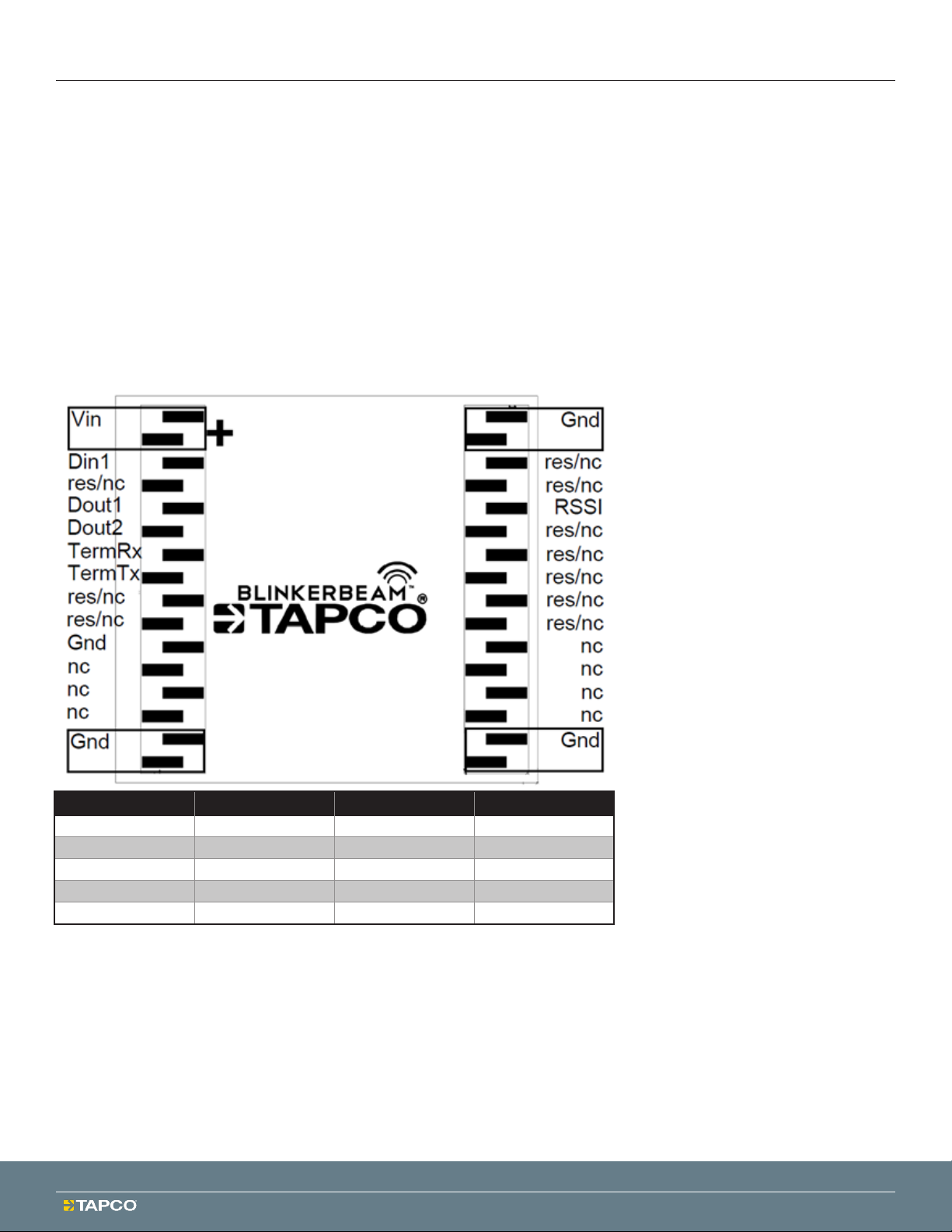
FEATURES
Standard IO- 2digital input lines,2 digital output lines,
host serial lines for OTA serial.
Options - 10additional IO/serial communication lines
are available for customization via custom factory
firmware modification.
120kBaud
Serial data rate is 19.2kBaud.
Green LED signaling RF Transmission and Timekeeper
Beacons.
RED LED signaling RF Packet Reception.
Ratings
Operating Temperature -40 to 80C
Operating Voltage 5VDC at Vin relative to ground
Operating Voltage on all io/serial lines is 0V to 3.3V DC.
Operating Humidity < 90%
When operating outdoors use anappropriately rated
enclosure toprevent moisture from contacting the
module.
RF Output Maximum 20dBm (+/- 1.1dB)
RF Frequency range >= 902.4MHz and <= 927.6MHz

Radio RM8003-03 User Guide
3
Available Antennas
1. 5.15dBi Halfwave OMNI Fiberglass
2. 3dBi Omni Whip antenna - RPSMA
3. 4dBi Omni Low Prole ‘Puck’ shaped Antenna
4. 10.65dBi Yagi
FCC INFORMATION
FCC-Approved Antennas
NOTICE
This equipment is approved only for mobile and base station transmitting devices. Antenna(s) used for this
transmitter must be installed to provide a separation distance of at least 20 cm from all persons and must not be co-
located or operating inconjunction with any other antenna or transmitter.
Radio RM8003-03 Module may be used only with Approved Antennas that have been tested with this module.
Warnings
Radio RM8003-03 is intended to be installed in a fixed location.
A minimum separation distance ≥ 20 cm is required between the antenna and radiating structures of the device
and nearby persons.
Radio RM8003-03 will be sold with fixed power levels respective of the antenna that is provided and network
data rate that is programmed into the radio by the manufacturer.
The user shall not make changes or modifications to Radio RM8003-03 unless expressly approved by TAPCO or
the consequences could void the user’s authority tooperate the equipment.
FCC ID: 2ANWN-RM8003-03
This device complies with part 15ofthe FCC Rules. Operation issubject tothe following two conditions: (1)
This device may not cause harmful interference, and (2) this device must accept any interference received,
including interference that may cause undesired operation.
The host device in which the module is installed shall have on its label, the statement
“Contains FCC ID: 2ANWN-RM8003-03” or if an electronic display is used, it will be available without need
of password protection and will be available in less than 3 steps from the main menu.
The host product manufacturer isresponsible for compliance toany other FCC rules that apply tothe host
and is not covered by the modular transmitter grant of certification.
Industry Canada IC ID: 25608-RM800303
This device complies with Industry Canada license-exempt RSS standard(s).
Operation is subject to the following three conditions:
1. This device may notcause interference,(2) this device must accept any interference, including interference that
may cause undesired operation of the device, and (3) Radio RM8003-03 and available antenna options must be
used at a distance greater than 20cm from the user.
Le present appareil est conforme aux CNR d’Industrie Canada applicables aux appareils radio exempts de licence.
L’exploitation est autorisee aux deux conditions suivantes:
l’appareil ne doit pas produire de brouillage, et
l’utilisateur de l’appareil doit accepter tout brouillage radioelectrique subi, meme si le brouillage est
susceptible d’en compromettre le fonctionnement
La Radio RM8003-03 et les options d'antenna disponibles doivent être utilisées à une distance supérieure à
20 cm de l'utilisateur.

4
Radio RM8003-03 User Guide
The host device in which the module is installed shall have on its label, the statement:
"Contains IC: 25608-RM800303"
or if an electronic display is used, it will be available without need of password protection and will be
available in less than 3 steps from the main menu.
Installation Instructions
To satisfy ISED Canada RF exposure requirements, Radio RM8003-03 and available antenna options must be
used at a distance greater than 20 cm from the user.
HOOKUP AND LAYOUT
Ratings Min. Nom. Max.
Vin 4.5V 4.8V 5.2V
Din1 0V - 3.3V
Dout1/2 0V - 3.3V
TermTx/Rx 0V - 3.3V
RSSI 0V - 3.3V
Din1 is a Buffered Input with min active Low voltage 0.7V and Active High voltage 2.5V.
Dout1/2 are push pull outputs.
RSSI uses 8bit 1 start 1 stop bit active low 460,800baud to transmit RSSI information in ascii format.
TermTxRx uses 8bit 1 start 1 stop bit active low 19,200baud to transmit and receive serial data over the air.
TermTx is in reference to the Host TX and TermRx is in reference to Host Rx.

Radio RM8003-03 User Guide
5
HOST LAYOUT
TAPCO suggested Host layout using Samtec SMM-116-02-S-S
*Host layout may use any 2mm pitch connector suitable for mating with Samtec TMM-116-01-S-S-SM.
Frequency Hopping Spread Spectrum
A FHSS radio does just what its name implies – that is, it ‘hops’ from frequency to frequency over a wide band. The
specific order inwhich frequencies are occupied isfixed butina pseudo random order.
Modes ofOperation
The Radio RM8003-03 has 4 operating functions:
Transmit serial data
Receive serial data
Hardware IO control
Hardware Beacon outputs
Hardware IO mode acts like a one to many remote controls so when Digital input one on any device is activated,
the radio broadcasts this information to all other radios on a synchronized beacon. When a remote device receives
information that one of the other radios Digital Input 1 has been activated, it activates its Digital Output 1.
Hardware Beacon outputs are configurable at the factory to output a beacon pulse on Digital Output 2 in any 1
second period increment. The Fundamental System Timekeeper generates the timing for this pulse and keeps
Listener radios updated as to the status of this Hardware Beacon Pulse.
Serial Data Received on any radio will be directed to the remote radio device that is getting addressed by the host
application.
Local Serial Data received for device configuration will not be transmitted on the RF network.

6
Radio RM8003-03 User Guide
Transmit Mode
All packets sent over the air are either Addressed or Broadcast packets. Broadcast and Addressed delivery can be
controlled dynamically with the API Control byte. Contact the factory for details.
When a radio has data to transmit, it sends it out on its reserved timeslot. The number of devices on a network is
configurable atthe factory.
To increase the odds of successful delivery the host application is required to Transmit Retries.
RF Serial Communication is not transparent to the OEM host and the Manufacturer will need to advise the Host on
how to apply data packaging for transmission OTA (over the air). Contact the factory for details.
Receive Mode
Serial data can be asynchronously received by Radio RM8003-03 OTA then directed to the Host serial port.
RSSI - Received Signal Strength
RSSI is in units of dBm and is available through serial communication. Contact the factory for details on reading this
information from the transceiver.
System Timing and Latency
Latency is the amount of time that it takes for an action to take place. There are different actions available in TapNet
including remote digital control andserial data transmission/reception.
IO latency is dependent on the size of the RF network.
Device networks require a maximum of 143ms for one transceiver to transmit information to the system and in as
little as 9ms to transmit information directly.
System Throughput
Maximum System Throughput
Timekeeper to Listener = 1280 baud continuous max
host throughput rate
Listener to Listener in direct mode = 1280 baud
continuous max rate
Listener to Listener in sync mode = 640 bytes baud
continuous
Maximum host serial payload size is 64 bytes.
RF Data Rate default is 120kBaud.
Other data rates and payload sizes are available. Contact TAPCO for details on custom serial data configurations.
System Operation
The Radio RM8003-03 network is preconfigured at the factory so all the user needs to do is power up the devices
and they will automatically sync and begin working. IO and OTA serial functionality is only available once a
device is sync’d.
A flashing green LED indicates the TimeKeeper device. The Green LED specifically indicates that data has been
transmitted OTA.
A red flashing LED indicates that a Listener Device is in sync with the TimeKeeper. The Red LED specifically
indicates that RF data has been received OTA.

Radio RM8003-03 User Guide
7
ORDERING INFORMATION
This radio transmitter 25608-RM800303 has been approved byInnovation, Science and Economic Development
Canada to operate with the antenna types listed below, with the maximum permissible gain indicated. Antenna
types not included in this list that have a gain greater than the maximum gain indicated for any type listed are
strictly prohibited for use with this device.
Product Part Number: Radio RM8003-03 – Radio Transceiver Module
Available Antennas:
Antennas:
TAPCO Part No: 146299, Max 4dBi 50 Ohms, Dome
Style Antenna Kit with 24” COAX
TAPCO Part No: 149096, Max 5.15dBi 50 Ohms,
Halfwave Omni Base Station Antenna
TAPCO Part No: 101962, Max 3dBi 50 Ohms,
Whip Antenna
TAPCO Part No: 1343-00006, Max 10.65dBi 50
Ohms, Yagi Antenna
Antenna Accessories:
Lightning Arrestor, L-com Model AL-NFNFB L-Com Cable Model CA-RSPNMA002
Antennas with connectors that do not meet the requirement of a non-standard antenna connector will have an
adapter permanently connected with industrial epoxy, “Loctite” or solder to make the connection permanent prior
to shipping.

© 2022 Trac and Parking Control Co., Inc. |5100 West Brown Deer Rd., Brown Deer WI 53223 |Phone (800) 236-0112 |FAX (800) 444-0331 |TAPCOnet.com
8 am–5 pm (CST) Monday through Friday
For faster service, have the serial number on the TAPCO® cabinet label ready.
(800) 236-0112 TAPCOnet.com
TAPCO is a leader in the design and manufacture of customized, performance-critical products for wireless and other
advanced electronics applications. TAPCO partners with its customers to provide solutions for various applications
such as:
Intelligent Warning Systems
Trac Signals and Intelligent Transportation Systems
Cloud-based Trac Device Management
Parking and Security Systems
Custom Trac Signs and Accessories
Streetscape Decoratives
Signmaking and Inventory
Sign Post Anchoring
Federal Applications
TAPCO offers its customers unique product solutions, dedication to research and development, as well as a seamless
network of manufacturing and customer support facilities across the globe.
Copyright ©2021 Traffic and Parking Control Company, Inc. (TAPCO®) All rights reserved. The information contained in
this manual and the accompanying software programs are copyrighted and all rights are reserved by TAPCO.
TAPCO reserves the right to make periodic modifications of this product without obligation to notify any person
or entity of such revision. Copying, duplicating, selling, or otherwise distributing any part of this product or
accompanying documentation/software without the prior consent of an authorized representative of TAPCO is
strictly prohibited. All brands and product names in this publication are registered trademarks or trademarks of their
respective holders.
Information furnished by TAPCO in this specification is believed to be accurate. Devices sold by TAPCO are covered
by the warranty and patent indemnification provisions appearing in its Terms of Sale only. TAPCO makes no warranty,
express, statutory, and implied or by description, regarding the information set forth herein. TAPCO reserves the
right to change specifications at any time and without notice. TAPCO’s products are intended for use solely in normal
commercial and industrial applications. Applications requiring unusual environmental requirements such as military,
medical life-support or life-sustaining equipment are specifically not recommended without additional testing for such
application.
1020-RM8003-03 06/08/22
Table of contents