manuals.online logo
Brands
  1. Home
  2. •
  3. Brands
  4. •
  5. Tapco
  6. •
  7. Speakers
  8. •
  9. Tapco S8 User manual

Tapco S8 User manual

Other Tapco Speakers manuals

Tapco 6912 User manual

Tapco

Tapco 6912 User manual

Tapco S-5 User manual

Tapco

Tapco S-5 User manual

Tapco S-5 User manual

Tapco

Tapco S-5 User manual

Tapco THUMP TH-15A User manual

Tapco

Tapco THUMP TH-15A User manual

Tapco S-5 Technical document

Tapco

Tapco S-5 Technical document

Tapco S-5 User manual

Tapco

Tapco S-5 User manual

Popular Speakers manuals by other brands

Electro-Voice LR4S engineering data

Electro-Voice

Electro-Voice LR4S engineering data

Definitive Technology Sound Cylinder user guide

Definitive Technology

Definitive Technology Sound Cylinder user guide

AudioSource LS545 user manual

AudioSource

AudioSource LS545 user manual

Paso C402-T Instructions for use

Paso

Paso C402-T Instructions for use

Altec Lansing 416-8C LF SPEAKER manual

Altec Lansing

Altec Lansing 416-8C LF SPEAKER manual

Kenwood KFC-1072 Servise manual

Kenwood

Kenwood KFC-1072 Servise manual

Peavey ProSys 112 user guide

Peavey

Peavey ProSys 112 user guide

JBL Control Contractor 60 Series installation instructions

JBL

JBL Control Contractor 60 Series installation instructions

Aura STORM-8 owner's manual

Aura

Aura STORM-8 owner's manual

Oontz ANGLE 3 PLUS quick start guide

Oontz

Oontz ANGLE 3 PLUS quick start guide

Electro-Voice LR4A engineering data

Electro-Voice

Electro-Voice LR4A engineering data

Rave RK-650-ICA-B owner's manual

Rave

Rave RK-650-ICA-B owner's manual

Flux Reference Series installation manual

Flux

Flux Reference Series installation manual

Lanzar AQAWBS64BK installation manual

Lanzar

Lanzar AQAWBS64BK installation manual

DAPAudio DCS-6230 manual

DAPAudio

DAPAudio DCS-6230 manual

Aluratek ABS03F quick start guide

Aluratek

Aluratek ABS03F quick start guide

Kenwood KES-5A instruction manual

Kenwood

Kenwood KES-5A instruction manual

Sonance ORIGINAL SERIES instruction manual

Sonance

Sonance ORIGINAL SERIES instruction manual

manuals.online logo
manuals.online logoBrands
  • About & Mission
  • Contact us
  • Privacy Policy
  • Terms and Conditions

Copyright 2025 Manuals.Online. All Rights Reserved.

2
SAFETY INSTRUCTIONS
1. Read Instructions — All the safety and operation instructions
should be read before this product is operated.
2. Retain Instructions — The safety and operating instructions
should be kept for future reference.
3. Heed Warnings — All warnings on this product and in these
operating instructions should be followed.
4. Follow Instructions — All operating and other instructions
should be followed.
5. Water and Moisture — This product should not be used near
water for example, near a bathtub, washbowl, kitchen sink,
laundry tub, in a wet basement, near a swimming pool, etc.
6. Cleaning — Clean only with a dry cloth.
7. Ventilation — This product should be situated so that its location
or position does not interfere with its proper ventilation. For
example, the Component should not be situated on a bed,
sofa, rug, or similar surface that may block any ventilation
openings, or placed in a built-in installation such as a bookcase
or cabinet that may impede the fl ow of air through ventilation
openings.
8. Heat — This product should be situated away from heat
sources such as radiators, or other devices which produce
heat.
9. Power Sources — This product should be connected to a
power supply only of the type described in these operation
instructions or as marked on this product.
10. Power Cord Protection — Power supply cords should be routed
so that they are not likely to be walked upon or pinched
by items placed upon or against them, paying particular
attention to cords at plugs, convenience receptacles, and
the point where they exit this product.
11. Object and Liquid Entry — Care should be taken so that
objects do not fall on, and liquids are not spilled into, this
product.
12. Damage Requiring Service — This product should be serviced
only by qualifi ed service personnel when:
A. The power-supply cord or the plug has been damaged; or
B. Objects have fallen, or liquid has spilled into this product; or
C. This product has been exposed to rain; or
D. This product does not appear to operate normally or
exhibits a marked change in performance; or
E. This product has been dropped, or its chassis damaged.
13. Servicing — The user should not attempt to service this
product beyond those means described in this operating
manual. All other servicing should be referred to the Tapco
Service Department.
14. To prevent electric shock, do not use this polarized plug with
an extension cord, receptacle or other outlet unless the
blades can be fully inserted to prevent blade exposure.
Pour préevenir les chocs électriques ne pas utiliser cette fi che polariseé avec
un prolongateur, un prise de courant ou une autre sortie de courant, sauf si les
lames peuvent être insérées à fond sans laisser aucune pariie à découvert.
15. Grounding or Polarization — Precautions should be taken so
that the grounding or polarization means of this product is not
defeated.
16. Power Precaution — Unplug this product during lightning
storms or when unused for long periods of time.
17. This apparatus does not exceed the Class A/Class B
(whichever is applicable) limits for radio noise emissions
from digital apparatus as set out in the radio interference
regulations of the Canadian Department of Communications.
ATTENT ON —Le présent appareil numérique n’émet pas de bruits radioélectriques
dépassant las limites applicables aux appareils numériques de class A/de class B
(selon le cas) prescrites dans le règlement sur le brouillage radioélectrique édicté
par les ministere des communications du Canada.
18. Exposure to extremely high noise levels may cause permanent
hearing loss. Individuals vary considerably in susceptibility to
noise-induced hearing loss, but nearly everyone will lose some
hearing if exposed to suffi ciently intense noise for a period of
time. The U.S. Government’s Occupational Safety and Health
Administration (OSHA) has specifi ed the permissible noise
level exposures shown in the following chart.
According to OSHA, any exposure in excess of these permissible limits
could result in some hearing loss. To ensure against potentially dangerous
exposure to high sound pressure levels, it is recommended that all persons
exposed to equipment capable of producing high sound pressure levels
use hearing protectors while the equipment is in operation. Ear plugs or
protectors in the ear canals or over the ears must be worn when operating
the equipment in order to prevent permanent hearing loss if exposure is in
excess of the limits set forth here.
WARNING — To r duc th risk of fi r or l ctric shock,
do not xpos this applianc to rain or moistur .
Duration Per Day Sound Level dBA, Typical
n Hours Slow Response Example
8 90 Packed garage concert
6 92
4 95 VW Bus Peace Train
3 97
2 100 Cranked psychedelic tunes
1.5 102
1 105 High speed chase on C.H. .P.s
0.5 110
0.25 or less 115 Loudest parts at a Heavy Metal concert
CAUTION AVIS
RISK OF ELECTRIC SHOCK
DO NOT OPEN
R SQUE DE CHOC ELECTR QUE
NE PAS OUVR R
CAUTION: TO REDUCE THE RISK OF ELECTRIC SHOCK
DO NOT REMOVE COVER (OR BACK)
NO USER-SERVICEABLE PARTS INSIDE
REFER SERVICING TO QUALIFIED PERSONNEL
ATTENT ON: POUR EV TER LES R SQUES DE CHOC
ELECTR QUE, NE PAS ENLEVER LE COUVERCLE. AUCUN
ENTRET EN DE P ECES NTER EURES PAR L'USAGER. CONF ER
L'ENTRET EN AU PERSONNEL QUAL F E.
AV S: POUR EV TER LES R SQUES D' NCEND E OU
D'ELECTROCUT ON, N'EXPOSEZ PAS CET ART CLE
A LA PLU E OU A L'HUM D TE
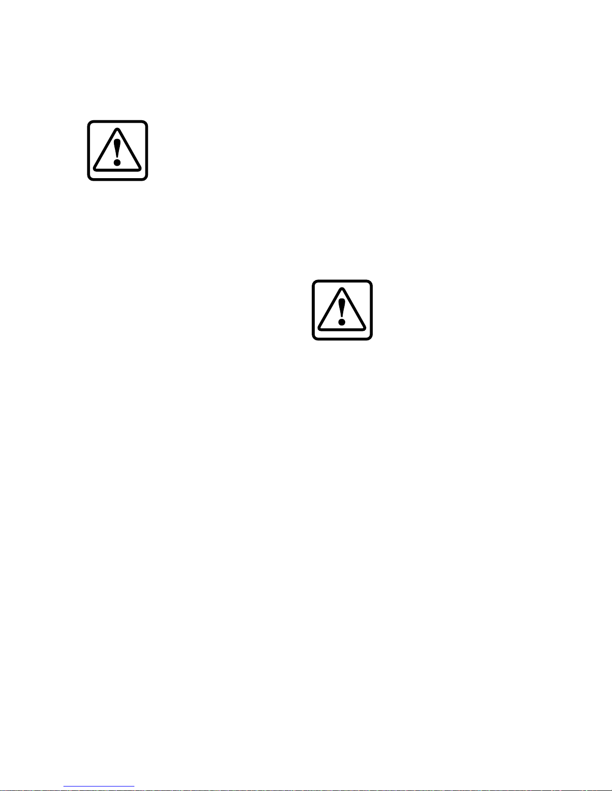
The lightning flash with arrowhead symbol within an equilateral
triangle is intended to alert the user to the presence of uninsulated
“dangerous voltage” within the product’s enclosure that may be
of sufficient magnitude to constitute a risk of electric shock to persons.
Le symbole éclair avec point de flèche à l'intérieur d'un triangle
équilatéral est utilisé pour alerter l'utilisateur de la présence à
l'intérieur du coffret de “voltage dangereux” non isolé d'ampleur
suffisante pour constituer un risque d'éléctrocution.
The exclamation point within an equilateral triangle is intended to
alert the user of the presence of important operating and maintenance
(servicing) instructions in the literature accompanying the appliance.
Le point d'exclamation à l'intérieur d'un triangle équilatéral est
employé pour alerter les utilisateurs de la présence d'instructions
importantes pour le fonctionnement et l'entretien (service) dans le
livret d'instruction accom
p
a
g
nant l'a
pp
areil.
Part No. 0008404 Rev. A 10/03
©2003 LOUD Technologies Inc. All Rights Reserved. 3
What m , r ad a manual?
Before you begin, please make sure you read the Safety Instructions on page 2 and
Getting Started on page 4.
Your new TAPCO® S•8 monitors are designed to set up quickly and operate easily.
We know it’s often seen as a sign of weakness to read a manual, along with asking for
directions when lost, but we hope you will read the rest of the manual, at least while
nobody is looking.
It is important to keep your receipt in a safe place, and not a bad idea to write your
product information here for future reference (i.e., insurance claims, tech support, return
authorization, etc.).
Contents
Safety Instructions.....................................................2
Getting Started .........................................................4
Placement.................................................................4
Introduction...............................................................6
Hookup Diagrams.....................................................7
TAPCO S•8 Features .................................................8
Rear Panel Description .......................................8
1. INPUTS ............................................................8
2. INPUT LEVEL ...................................................8
3. HIGH FREQ Switch ........................................8
4. LOW FREQ Switch .........................................9
5. AC SELECT .....................................................9
6. POWER...........................................................9
7. Line Cord Socket and Fuse .........................9
8. Bass Refl ex Port .............................................9
9. Heatsink .........................................................9
Front Panel Description.......................................9
10. Power LED .....................................................9
11. Clip LED .........................................................9
Protection Circuits ..................................................10
Input Signal Wiring ..................................................10
Appendix A: Service Information..........................11
Appendix B: Connections......................................13
Appendix C: Specifi cations...................................14
TAPCO LIMITED WARRANTY....................................15
Don’t forget to visit our website at www.tapcogear.com
for more information about this and other TAPCO products.
Product S rial #:
Purchas d at:
Dat of purchas :
Speaker 1 Speaker 2
4
Getting Started
The following steps will
help you set up your
monitor speakers quickly.
Follow these steps for all
the S•8 studio monitors in
your system.
INITIAL SETTINGS:
1. Turn the INPUT LEVEL control on the rear panel all
the way down.
2. Set the HIGH FREQ and LOW FREQ switches to “0
(NORMAL).”
3. Turn the POWER switch OFF.
CONNECTIONS:
1. Connect the line-level monitor signal from your
mixer (or other signal source) to the INPUT jack on
the S•8 Studio Monitor (XLR, 1/4-inch TRS, or RCA).
2. Set the AC SELECT switch to the correct position for
your country (115 VAC or 230 VAC).
3. Connect the supplied AC power cord to the IEC
socket on the back of the monitor. Plug the other
end into an AC outlet properly confi gured with the
correct voltage for the AC SELECT switch setting
you have selected.
TURN IT ON:
1. Turn the POWER switch ON.
2. Start your signal source (tape deck, CD, DAW, or
whatever), but leave the master level control on
your mixer down.
3. Slowly turn up the INPUT LEVEL control on the S•8 to
MAX (fully clockwise).
4. Adjust the master volume on your mixer to a
comfortably loud listening level. If the volume from
the speakers gets really loud, really fast, try turning
down the INPUT LEVEL control on the S•8s a bit to
achieve a good balance of master volume control
and loudness from the speaker.
Now that you have your monitors working,
it’s time to hunker down and read the rest of
this manual…especially the following:
Placement
An Extremely Important
Note on S•8 Bass
Response and Your
Control Room
Your new S•8s achieve their best bass
response in a room that’s optimized for bass
reproduction. A lot of factors can conspire
to thwart the S•8s’ extended low frequency,
including room shape, room volume, and
acoustical treatment.
This is not a cop-out or an apology. It’s
plain old physics in action. Luckily, we’ve
armed you with some compensating
controls that you can use to optimize the
frequency response of the speakers in your
particular room. Consider the following:
Low-Fr qu ncy R spons
When you put your S•8s in a corner or
up against a wall, their bass characteristics
change. The apparent loudness of the low
frequencies increases when the monitors
are placed close to a wall, and even more
so when they are placed in a corner.
If you have placed the speakers away
from the walls and corners and you would
like to hear a little more bass, try setting the
LOW FREQ equalization switch to the +2 dB
position to provide a gentle boost to the
low frequencies (below 100 Hz). If it’s still
not enough bass, try the +4 dB position to
provide a little more bass boost.
LOOK
CLOSER
BROUGHT TO YOU BY THE GROOVY FOLKS
IN WOODINVILLE, WASHINGTON, USA
MANUFACTURED IN CHINA
•
FABRIQUE AU CHINE
©2003 MACKIE DESIGNS, INC.
205323
CUS
R
WARNING: TO REDUCE THE RISK OF FIRE OR ELECTRIC SHOCK,
DO NOT EXPOSE THIS EQUIPMENTTO RAIN OR MOISTURE. DO NOT REMOVE COVER.
NO USER SERVICEABLE PARTS INSIDE. REFER SERVICINGTO QUALIFIED PERSONNEL.
AVIS : RISQUEDE CHOC ELECTRIQUE — NE PAS OUVRIR
RISK OF ELECTRIC SHOCK
DO NOT OPEN
XLRRCA
INPUTS SETTINGS
LOW FREQ FILTER
HIGH FREQ FILTER
0
(NORMAL)
(BALANCED)
(BALANCED)
(UNBALANCED)
–
2dB +2dB
+2dB0
(NORMAL)
+4dB
TRS
AC SELECT
S•8 ACTIVE STUDIO MONITOR
CAUTION: REPLACE WITH THE SAME FUSE AND RATING.
DISCONNECT SUPPLY CORD BEFORE CHANGING FUSE.
~220-240VAC = T 800 m A L /250V FUSE
~100-120VAC =T 1.6 A L / 250V FUSE
ON
SERIAL/ D ATE CODE
~100-120 VAC/220 -240VAC 50-6 0 Hz 110W
INPUT
LEVEL
MAXOFF
115V
5
High-Fr qu ncy R spons
The S•8s are designed to provide a
smooth frequency response throughout the
mid and high range. Nevertheless, you may
decide that you need a little more or a little
less high frequencies in your monitors while
you’re mixing. The HIGH FREQ equalization
switch provides a gentle boost or cut in
the frequencies above 5 kHz. Remember
that boosting the high frequencies in the
monitors can result in a duller mix, while
reducing the high frequencies can result in
a brighter overall mix.
ADDITIONAL TIDBITS OF WIDSDOM:
• Never listen to loud music for prolonged periods.
Please see the Safety Instructions on page 2 for
information on hearing protection.
• When you shut down your equipment, turn off
the S•8 studio monitors fi rst to prevent thumps
and other noises generated by any upstream
equipment from coming out the speakers. When
powering up, turn on the monitors last.
• Save the shipping boxes and packing materials!
You may need them someday. Besides, your cat
will love playing in them and jumping out at you
unexpectedly. Remember to pretend like you are
surprised!
• Save your sales receipt in a safe place.
• Also record both S•8 serial numbers in the space
provided on the inside front cover, along with
where and when you bought them.
6
Here’s a quick look at all the features packed into the S•8 Studio Monitors:
• Flat frequency response (±3 dB, 40 Hz to 20 kHz)
• 1” silk dome tweeter, fully magnetically shielded
• 8” polypropylene cone woofer, fully magnetically
shielded
•
Convenient compact design, perfect for near-
fi eld monitoring
• Ported, bass refl ex design for enhanced bass
performance
• 60 watt HF and 60 watt LF power amplifi ers
• Low-frequency over-excursion protection
• Front panel clipping indicator
• High-strength cabinet constructed of 5/8” MDF
composite and 1” front board with radiused edges
• High-density adiabatic fi berfi ll absorbs internal
refl ections
• Full magnetic shielding allows placement near
computer monitors
• Balanced XLR and 1/4” TRS, and unbalanced RCA
input connectors
• 24 dB/octave crossover at 3 kHz
• Adjustable sensitivity control
• LF equalization provides +2 dB or +4 dB at 100 Hz
and below
• HF equalization provides ±2 dB at 5 kHz and above
• Rear panel power switch with front panel
indicating LED
Introduction
Thank you for choosing TAPCO S•8 Studio Monitors by LOUD
Technologies. The TAPCO product line hails back to the days of TAPCO
Corporation, Greg Mackie’s fi rst company. TAPCO revolutionized
the audio industry back in 1969 with the very fi rst 6-channel mixer
specifi cally designed for keyboards and rock ‘n’ roll.
In essence, TAPCO redefi ned the price/performance ratio and
made high-quality professional audio equipment accessible to virtually
anyone. Today, TAPCO is reborn with the same ideals and is backed by
the world-class engineering and manufacturing horsepower of LOUD
Technologies. The TAPCO S•8 is the second active studio monitor in the
TAPCO by Mackie® family, joining its sibling, the TAPCO S•5.
These versatile compact “mini-monitors” can be used in a variety of applications,
including small project studios, surround sound editing, home theater playback, and
desktop audio workstations (DAWs).
The S•8 active studio monitors are packed with features and designed to produce
transparent and uncolored sound for monitoring multitrack recordings and mixdowns. The
two-way bass refl ex (ported) design provides an amazingly fl at frequency response from
40 Hz to 20 kHz.
There are many benefi ts to integrating an active crossover, power amplifi ers, and drivers into
a single cabinet, and we’ve taken full advantage of these benefi ts in the design of the S•8.
• The crossover point is designed so that the high and low frequency drivers are fed only
the frequencies that they are best able to reproduce.
• The amplifi ers are designed to provide maximum acoustic output from the speakers,
yet minimize the danger of speaker damage due to overdriving.
• The connecting wire between the amplifi er outputs and the drivers are kept to an
absolute minimum so the damping factor of the amplifi er isn’t compromised by the
resistance of long speaker cables.
• The acoustic sum of the outputs from the two drivers are optimized electronically, as
well as physically, so the amplitude response is unity and the phase difference is minimal.
In short, all the complex interconnected components in the system are designed to work
in harmony with each other to produce the best possible sound.
TAPCO version of Greg
TAPCO van (a.k.a. micro bus)
7
Hookup Diagrams
St r o Sp ak r Hookup
Daisy-Chaining Two Sp ak rs P r Sid
Note: Use stereo 1/4”
TRS plugs for the “Thru”
connections. If you use
mono 1/4” TS plugs,
you will unbalance the
XLR connections and
suffer a drop in signal
level of 6 dB.
OFF
XLRPHONO
INPUTS SETTINGS
INPUT
LEVEL
LOW FREQ FILTER
HIGH FREQ FILTER
0
(NORMAL)
–2dB +2dB
TRS
S-8 ACTIVE STUDIO MONITOR
MAX
0
(NORMAL)
+2dB +4dB
OFF
XLRPHONO
INPUTS SETTINGS
INPUT
LEVEL
LOW FREQ FILTER
HIGH FREQ FILTER
0
(NORMAL)
–2dB +2dB
TRS
S-8 ACTIVE STUDIO MONITOR
MAX
0
(NORMAL)
+2dB +4dB
Mixer or
Preamplifier
Right
Line level
Output
Left
Line level
Output
1202-VLZ PRO
OFF
XLRPHONO
INPUTS SETTINGS
INPUT
LEVEL
LOW FREQ FILTER
HIGH FREQ FILTER
0
(NORMAL)
–2dB +2dB
TRS
S-8 ACTIVE STUDIO MONITOR
MAX
0
(NORMAL)
+2dB +4dB
OFF
XLRPHONO
INPUTS SETTINGS
INPUT
LEVEL
LOW FREQ FILTER
HIGH FREQ FILTER
0
(NORMAL)
–2dB +2dB
TRS
S-8 ACTIVE STUDIO MONITOR
MAX
0
(NORMAL)
+2dB +4dB
OFF
XLRPHONO
INPUTS SETTINGS
INPUT
LEVEL
LOW FREQ FILTER
HIGH FREQ FILTER
0
(NORMAL)
–2dB +2dB
TRS
S-8 ACTIVE STUDIO MONITOR
MAX
0
(NORMAL)
+2dB +4dB
OFF
XLRPHONO
INPUTS SETTINGS
INPUT
LEVEL
LOW FREQ FILTER
HIGH FREQ FILTER
0
(NORMAL)
–2dB +2dB
TRS
S-8 ACTIVE STUDIO MONITOR
MAX
0
(NORMAL)
+2dB +4dB
Thru
Thru
Mixer or
Preamplifier
Right
Line level
Output
Left
Line level
Output
1202-VLZ PRO
BROUGHT TO YOU BY THE GROOVY FOLKS
IN WOODINVILLE, WASHINGTON, USA
MANUFACTURED IN CHINA
•
FABRIQUE AU CHINE
©2003 MACKIE DESIGNS, INC.
205323
CUS
R
WARNING: TO REDUCETHE RISK OF FIRE OR ELECTRIC SHOCK,
DO NOT EXPOSE THIS EQUIPMENTTO RAIN OR MOISTURE. DO NOT REMOVE COVER.
NO USER SERVICEABLE PARTS INSIDE. REFER SERVICINGTO QUALIFIED PERSONNEL.
AVIS : RISQUEDE CHOC ELECTRIQUE —NE PAS OUVRIR
RISK OF ELECTRIC SHOCK
DO NOT OPEN
XLRRCA
INPUTS SETTINGS
LOW FREQ FILTER
HIGH FREQ FILTER
0
(NORMAL)
(BALANCED)
(BALANCED)
(UNBALANCED)
–
2dB +2dB
+2dB0
(NORMAL)
+4dB
TRS
AC SELECT
S•8 ACTIVE STUDIO MONITOR
CAUTION: REPLACE WITH THE SAME FUSE AND RATING.
DISCONNECT SUPPLY CORD BEFORE CHANGING FUSE.
~220-240VAC = T 800 m A L /250V FUSE
~100-120VAC =T 1.6 A L / 250V FUSE
ON
SERIAL/ D ATE CODE
~100-120 VAC/220-240VAC 50 -60 Hz 110W
INPUT
LEVEL
MAXOFF
115V
8
TAPCO S•8 Features
REAR PANEL
DESCRIPTION
This is where
you connect
your signal to the
monitor and make
adjustments to
the frequency
response of
the speakers
to match the
monitor’s location
and your room’s
environment.
1. INPUTS
• Since all three
of them are
connected
together
electrically, do not
connect more than
one signal at a
time to the jacks.
• You can use the
remaining jacks
as “Thru” jacks for
daisy-chaining the
signal to another
monitor or to
another amplifi er.
If you do this,
be aware that
unbalancing the
signal anywhere
along the
chain does so for all devices connected to the
chain. This negates the benefi ts associated with
balanced lines and inputs.
•
Unbalanced TS (Tip-Sleeve) lines can be
accommodated via the TRS jack. See “Appendix B:
Connections” for more information.
•
When using a TS or TRS plug, make sure it is pushed all
the way into the jack. Partially inserting the plug into
the jack could result in a drop in signal level (by 6 dB).
• The S•8s can be used with a home receiver even
if the receiver lacks a preamp output by using a
speaker-level to line-level attenuator. (See “Input
Signal Wiring” on page 10 for more information.)
2. INPUT LEVEL
The S•8 expects a line-level signal at its input. Use
this control to adjust the sensitivity of the input section
according to the signal strength at its input.
•
The S•8 is designed to operate with a +4 dBu signal
when the INPUT LEVEL control is at the MAX position.
• The S•8 can accept
up to a +20 dBu signal
by turning down the
INPUT LEVEL control
accordingly.
• NEVER connect the
output of an amplifi er
directly to the input
of the S•8. This could
damage the input
circuitry of the studio
monitor.
3. HIGH FREQ
Switch
The HIGH FREQ
switch tailors
the overall high-
frequency response
by ±2 dB at 5 kHz
and above. Leave
this switch in the “0
(NORMAL)” position
unless:
• You want to subtly
brighten or darken
the sound of the
speakers.
• Perhaps you have
hearing loss caused
by too many nights
in front of a double
Marshall stack.
• You just like to mix on the bright side or dull side.
If your mixes consistently sound dull or dark when
you listen elsewhere, this usually indicates that your
monitors are too bright, relative to your normal
hearing. A bit less high-frequency energy usually fi xes
this, and you can force the mix in this direction by
reducing the high-frequency output of the monitors
by using the 2 dB position of the switch.
Conversely, if your mixes are consistently too bright,
then adding some additional high-frequency energy
in the monitors satisfi es your ears, and the resultant mix
has less HF content.
It’s a real rush to mix really loud. But remember that
the resulting mix only sounds good when you play it at
least that loud. However strange it may sound, mixes
made at lower levels sound even better when played
loud, perhaps even a bit bigger than life.
12
3
4
5
6
7
8
9
9
Get that sound level meter out. Decide what level
you’re going to mix at and use the meter to help keep
you mixing at that
level. Your ears will
thank you, and your
mixes will be better
for it.
4. LOW FREQ
Switch
The LOW FREQ
switch tailors the overall
low-frequency response
by +2 dB or +4 dB at
100 Hz and below.
• For most
applications, use
the “0 (NORMAL)”
setting. This takes
the equalization
circuit out of the
signal path.
•
If you want or need
just a little extra low-
frequency output,
use the +2 dB setting.
• If you want or
need more low-
frequency output,
use the +4 dB
setting. Remember
how things work in
reverse, so boosting
the deep bass
content on playback
may actually decrease it in
the fi nal mix.
5. AC SELECT
Set this switch to the correct voltage setting for the
country you are in, 115 VAC or 230 VAC.
Not : The S•8s are shipped with the AC SELECT
switch set to the 230 VAC position. If you are in a
country that uses 100-120 VAC, set the switch to the
115 VAC position and replace the fuse (located in
the IEC socket) with the 1.6 A fuse included in the
accessory bag. See the “Troubleshooting” section on
page 11 for instructions on replacing the fuse.
6. POWER
Use this switch to turn the active monitors on and off.
7. Lin Cord Sock t and Fus
Connect the line cord to this IEC socket securely,
and plug the other end into your AC outlet. Make sure
the AC SELECT switch is set to the correct AC voltage.
The fuse is located behind the fuse cover, at the
bottom of the IEC socket. See the “Troubleshooting”
section on page 11
for information about
replacing the fuse.
8. Bass R fl x
Port
A bass refl ex system
uses the radiation
from the rear of
the woofer cone
to extend the low-
frequency response of
the speaker. The size
of the port is carefully
designed with respect
to the volume of
the cabinet and the
characteristics of the
woofer to produce low-
frequency extension.
9. H atsink
The heatsink is
designed to dissipate
the heat generated
by the built-in power
amplifi ers. The cooler
the amplifi ers operate,
the longer their life-
expectancy. The
S•8 uses convection
cooling, where cool air
fl ows through the fi ns of the heatsink and carries the heat
away. Make sure there is at least six inches clearance
between the back of the S•8 monitors and the wall.
FRONT PANEL DESCRIPTION
10. Pow r LED
This illuminates when the POWER switch is turned on
and AC power is available at the line cord socket.
11. Clip LED
This LED illuminates just before the low-frequency
amplifi er reaches its maximum output and begins to clip.
• Occasional blinking of the Clip LED indicates that
the loudest transients are reaching the maximum
output capability of the amplifi er. This is okay.
• Frequent or continuous blinking of the Clip LED
indicates that you have exceeded the maximum
output capability of the amplifi er and that the
amplifi er is clipping. You should reduce the level
from your signal source until the Clip LED blinks
occasionally or not at all.
10 11
10
Prot ction Circuits
There are several protection mechanisms designed
into the S•8 to safeguard the loudspeakers and
amplifi ers from inadvertent damage.
CAUTION: The protection
circuits are designed to protect the
loudspeakers under reasonable
and sensible conditions. Should you
choose to ignore the warning signs
(i.e., frequent Clip LED indications,
excessive distortion), you can still damage the
speakers in the S•8 by overdriving them past the point
of amplifi er clipping. Such damage is beyond the
scope of the warranty.
Ov r xcursion Prot ction
A 12 dB/octave high-pass fi lter at 40 Hz just prior
to the low-frequency amplifi er prevents very low
frequencies from being amplifi ed. Excessive low-
frequency energy below 40 Hz can damage the
woofer by causing it to “bottom out,” also known as
overexcursion, which is equivalent to a mechanical
form of clipping.
Th rmal Prot ction
All amplifi ers produce heat. The S•8 is designed to
be effi cient both electrically and thermally.
• If for some reason the heatsink gets too hot, a
thermal switch activates and turns off the amplifi er.
This protection operates independently for the
low-frequency and high-frequency amplifi ers.
Therefore, it is possible for only the low frequency
or high frequency amplifi er to shut down while the
other remains on.
• When the heatsink cools down to a safe
temperature, the thermal switch resets and normal
operation resumes.
• If the heatsink temperature again gets too hot, the
shutdown process repeats. Should this happen,
make sure that airfl ow to the rear of the cabinet
is not restricted. If the ambient air temperature
is very warm, try pointing a small fan toward the
heatsink to increase the airfl ow through the fi ns.
Int grat d Magn tic Shi lding
The S•8 contains drivers with large magnetic
structures. The drivers’ magnets are shielded to help
prevent the magnetic fi eld from radiating out into
the environment and playing havoc with computer
monitors or TV screens. Unshielded speakers can
cause distortion in both the shape and color of the
picture if placed too close to a CRT (cathode ray
tube). If you have a particularly sensitive computer
monitor or TV screen, it may be necessary to move
the speakers a few inches away.
Input Signal Wiring
You should use high-quality, shielded cable to
connect the signal source to the INPUT jack on the S•8.
• Foil shielded cables, such as Belden 8451, 8761, or
9501 are commonly used for studio wiring.
• Microphone cables work well.
• The better the shield, the better the immunity from
externally induced noise (like EMI and RFI). Route
the cable away from AC power cords and outlets.
These are common sources for hum in an audio
signal. You can purchase quality cables from your
Mackie dealer.
• In certain home theater applications, it may be
necessary to connect the speaker outputs from
a stereo receiver to the inputs of the S•8s, if the
receiver doesn’t have preamp outputs or other
line-level output connections.
CAUTION: Do not attempt to
connect a speaker output directly
to the input of the S•8! Speaker
levels are much higher than line
levels and can damage the input
circuitry in the S•8.
You can, however, insert a speaker-level-to-
line-level signal attenuator between the receiver’s
speaker output and the S•8’s input. Your Mackie
dealer may be able to help you fi nd one, or if you
enjoy do-it-yourself projects, you can build your own.
Contact our tech support department for more
information.