Tapeswitch CKP/Solo Sensors User manual

IMPORTANT
Thismanualmustaccompanytheproductthroughoutitsworking
life. Those persons responsible for the use of the product must
ensurethatallpersonsinvolvedintheinstallation,commissioning,
operation, maintenance and servicing of the product have access
to all the information supplied by the manufacturers of the
machine and its safety system.
WARNING
Tapeswitch safety mat systems are intended to protect operators
working at or neardangerous machinery. They can only perform
thisfunctioniftheyarecorrectlyfittedandinterfacedtoasuitable
machine. It is essential that the full contents of this manual and
all the authoritative documents referred to herein are fully
understoodbeforeanyattemptatinstallationismade.Ifindoubt
contact Tapeswitch or your Tapeswitch distributor.
TAPESWITCH
SAFETY MATS
CKP/Solo Sensors
TECHNICAL MANUAL 343184-01
English

2
CONTENTS
1.GENERAL
2.TECHNICALDESCRIPTION
2.1 SYSTEM OVERVIEW
2.2 SENSORS
3.DETERMINETHEDIMENSIONSOFTHESENSOR
4.INSTALLATION
4.1 GENERAL
4.2 SENSOR INSTALLATION
5.PERIODICCHECKING
5.1 GENERAL
5.2 COMMISSIONING CHECKS
5.3 SIX MONTHLY CHECKS
5.4 DAILY/SETTING CHECKS
6.OPERATION,MAINTENANCEANDSERVICING
6.1 OPERATION
6.2 MAINTENANCE
6.3 SERVICING
7.TECHNICALSPECIFICATION
7.1 CKP/Solo SENSORS
7.2 MATERIAL SPECIFICATION
7.3 ORDERING INFORMATION
8.CONTACTS

3
1.GENERAL
The CKP/Solo mat is a pressure sensitive
safety device designed to protect operators
working at or near dangerous machinery.
Thematisdesignedtomeettherequirements
ofBSEN1760-1:1998andcontainsanintegral
fail-safe functionwhichmonitorstheswitching
elementstoCategory3ofEN954-1providing
dual channel outputs.
Whencorrectly installedat and interfacedto
a machine via a suitable control, which
monitors the dual outputs of the mat, the
CKP/Solomatwill:
(a) detect a person present in the dangerous
area and prevent dangerous motion from
occurring.
(b) detect a person entering the dangerous
area and cause dangerous motion to cease
before the person can reach the dangerous
parts.
(c) a combination of (a) and (b). The area
covered by the sensor depends on which of
thefunctions(a),(b)or(c)istobeperformed.
NOTE:TheCKP/Solomatisnotsuitablefor
detectingchildren.
The CKP/Solo mat is ideal for use with
safety bus systems. The mats can connect
directly to the same kind of standard safety
bus I/O connection modules that are used to
connect E-Stop switches over the
bussystem.Thisismuchmoreconvientthan
thealternativeofhavinganadditionalcontrol
unitclosetothematsothatitcanprovidethe
volt-free,normallyclosedconnectionstothe
safety bus I/O module.
WARNING
The information contained in this
manual relates to the use of a CKP/Solo
mat, to provide a basic safety switching
device.
In some applications the CKP/Solo mat
may be used together with other
equipment to provide additional
functions and features i.e. for use with
Safety Bus systems. Any other
documentationsuppliedmustbeusedin
conjunction with this manual.
In some cases some installation
parameters, notably the positioning of
the mat in relation to the dangerous
parts of the machine, can be affected
and close attention must be paid to all
informationsuppliedwithallequipment.

4
2.TECHNICALDESCRIPTION
2.1 SYSTEM OVERVIEW
A sensor may consist of a single mat sensor
or a combination of mat sensors. When a
personstandsonthesensoritisdetected,and
bymeansofitsoutputswitchingdevices,the
sensor causes dangerous motion to cease or
be prevented.
IMPORTANT
From the above it can be seen that the
safe use of the CKP/Solo Mat relies not
only on the safety integrity of the mat
itself but also on its mechanical and
electrical interfacing to the machine.
The safety integrity of the CKP/Solo
mat itself is the responsibility of
Tapeswitch.
Proper mechanical and electrical
interfacing is the responsibility of the
user. Comprehensive information for
this purpose is provided in section 4 of
this manual.
2.2 SENSORS
2.2.1 SENSOR SHAPES AND SIZES
Mat sensors can be produced in any shape
andsizewhichmeetsthefollowingrestrictions:
- all corners, internal or external, to be 90º.
- the maximum width of a mat is 1200 mm.
- the maximum length of a mat is 2400 mm.
- the maximum total area is 2.88m².
Figure1 - Dimensions of the inactivearea
around outer edge of sensor
The dimensions of sensors and their layout
must be such access to the machine is not
possible without stepping on a sensor. It
should not be possible to move the sensors
or bridge them using boards, plates etc.
NOTE - CKP/Solo sensors have a 30mm
inactive area around the outer edges, which
means that the dimensions of the active area
(i.e. the area within which the application of
pressurewillactuatethesensor)is60mmless
than the overall dimensions of the mat as
showninFigure1.Thisshouldbekeptinmind
whenspecifyingthesizeofmatforaparticular
application.
2.2.2 CKP/Solo SENSORS
The construction of the CKP/Solo sensor is
shown in Figure 2.Anetwork of Tapeswitch
ribbon switching elements is sandwiched
between two thick sheets of PVC material.
The switching elements are connected in
series and are connected to the integral
fail-safe monitor. The switch elements are
adhered to the bottom layer.
30
ACTIVE
AREA
30
30 30

5
Thetoplayer isasheetof ribbed,heavyduty
mattingmaterial.Thismaterialisoflaminated
construction and is PVC based with special
additives and fillers to increase its abrasion
and chemical resistance. This material can
withstand years of pedestrian traffic and is
resistanttomostchemicalscommonlyfound
inanindustrialenvironmentincludingwater,
coolant, oil and hydraulic fluid.
The bottom sheet is a solid smooth rubber
mattingsheet.
Thetopsheet is 6.5mm thickandthe bottom
sheet is 6mm thick.
All the upper conductors of all the switch
elementsareconnectedtogetherandalllower
conductorsareconnectedtogether,effectively
creatingasinglenormallyopenswitch.Heavy
gauge tin plated copper wire is used for all
internal wiring and all connections to the
switching elements are direct solder joints.
The switches are self-bottoming and as a
resulttheycanwithstandveryhighloadsand
repeatedoperation.Severalmillionoperations
istypical.
Figure 2 - Construction of CKP/Solo
Mat Sensor Figure 3 - Construction of Tapeswitch
Switch Elements
TheconstructionoftheTapeswitchelements
isshowninFigure3.Eachswitchingelement
is a long normally open switch. The switch
consistsoftwocopperplatedsteelconductors
held apart at the sides by an insulator. When
pressure is applied to the bead, the two
conductors are forced together in the centre,
closing the switch.
PVC SLEEVE
UPPER CONDUCTOR
LOWER CONDUCTOR
INSULATOR
PVC SLEEVE
UPPER CONDUCTOR
LOWER CONDUCTOR
TOP
LAYER
SWITCH
LAYER
BOTTOM
LAYER
FAILSAFE
CONTROLLER

6
3.DETERMINETHEDIMENSIONS
OF THE SENSOR
The dimensions of the sensors and their
layoutmustbesuchthat,accesstothemachine
isnotpossiblewithoutsteppingonthesensor.
Thedimensionsofthedangerousareadepend
ontheparticularapplication.Theparameters
to be considered include:
- Speed of walk or arm movement
(typically1.6m/s).
- Armlength(typically0.85m).
- Length of stride (typically 0.7m).
- Response time of system.
- Position of dead zones.
- Overtravel of dangerous parts after
stop signal is generated
To determine the size of sensor needed, use
thissimpleformulabelow:
Active + 60mm = Overall Sensor
Area length or width
i.e.Forasensormeasuring2000mmx1000mm
the size of active area = 1940mm x 940mm.
Note that if the sensor is to be supplied and
fittedwithAE-13Aluminiumedgingthen:
Total Area = Overall Sensor + 126mm
Coveredwith length or width
AE-13Edging
i.e.Forasensormeasuring2000mmx1000mm
thetotalareacovered=2126mmx1126mm.
Inordertodeterminethepositionofthefront
edge of the active zone it is necessary to
consider the stopping performance of the
machine.
Anymachineregardlessoftheefficiencyofits
brakingsystem,willtakeacertainamountof
time to come to rest after a stop signal is
generated. From the instant that a persons
foot touches the sensor to the instant that the
dangerousmotionactuallyceasesiscalledthe
overall system response time.
Theoverallsystemresponsetime,T,isgiven
bythefollowingcalculation:
T = t1 + t2
where t1 = the maximum response time of
the safety device between the
actuation of the sensor and the
generation of the stop signal.
andt2 = theresponsetimeofthemachine
between receiving a stop signal
from the safety device and the
dangerous parts coming to rest.
Thedangerouspartswillobviouslycontinue
to move during this time. The sensor must
thereforebedimensionedsuchthatthenearest
point at which a person could first touch the
mat is a certain minimum distance from the
dangerous parts, to prevent the person from
reachingthedangerouspartsbeforetheyhave
stopped.
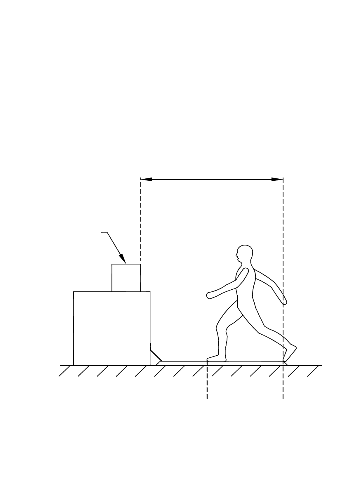
This must take into account the worst case
conditions illustrated in Figure 4 where a
person could be a full stride onto the sensor
beforethesensorisactuated.Thismeansthat
a certain distance from the front edge of the
sensor and the dangerous parts must be
maintained.
7
This distance is the minimum separation
distance.Allpossibledirectionsofapproach
mustbeconsidered.Theminimumseparation
distance, S, can be calculated using the
followingformula:
S = (1600 x T) + 1200
The overall system response time, T, should
be measured several times and the highest
valuerecorded,plusasuitableallowancefor
brake deterioration, should be used in the
calculationoftheminimumseparationdistance.
Figure 4 - Minimum Separation Distance
MINIMUMSEPARATION
DISTANCE 'S'
DANGEROUS
PARTS
MACHINE
WORST CASE
POINT OF
DETECTION
BEST CASE
POINT OF
DETECTION
FRONTEDGEOFACTIVEZONE
NEAREST DANGER POINT

8
4.INSTALLATION
WARNING
TAPESWITCH SAFETY MAT SYSTEMS ARE DESIGNED TO PROTECT
OPERATORS WORKING AT OR NEAR DANGEROUS MACHINES. THEY CAN
ONLY PERFORM THAT FUNCTION IF THEY ARE CORRECTLY FITTED AND
INTERFACED TO A SUITABLE MACHINE. EVERY EFFORT HAS BEEN MADE IN
THE PRODUCTION OF THIS MANUAL TO PROVIDE COMPREHENSIVE AND
ACCURATE INFORMATION. IT IS THE RESPONSIBILITY OF THE USER TO
ENSURE THAT ALL PERSONS INVOLVED IN THE INSTALLATION OF THE
PRODUCTHAVETHEKNOWLEDGE,TRAININGANDEXPERIENCENECESSARY
AND THAT THEY ARE FULLY CONVERSANT WITH ALL LAWS, RULES,
REGULATIONS AND CODES OF PRACTICE PERTAINING TO THEIR TASK.
4.1GENERAL
The attention of the installer is drawn to the
following general requirements for the
installationofaTapeswitchsafetymatsystem:
(a) The machine must be electrically
controllable.
(b) It must be possible to stop the dangerous
motion of the machine at any point in its
operation, in any operating mode.
(c) The control system as a whole must be
designedtoprovidethelevelofsafetyintegrity
determined by the risk assessment.
(d) Steps must be taken to prevent access to
thedangerous partsof themachine fromany
direction not covered by the sensor. Such
stepscouldincludefixedorinterlockingfences
orscreens,additionalpressuresensitivemats
or photo-electric devices.
(e) Steps must be taken to prevent a person
standinginthedangerousareawithoutstanding
on the sensor. The inner surfaces of fixed
mechanicalfencingshouldbedesignedsuch
that there are no ledges or steps on which a
person could stand and thereby avoid the
sensor. It may be necessary to fit additional
mechanicalbarriers,coversetc.tocoverany
surfaceswithin thedangerous areaonwhich
a person could stand, such as the feet of the
machine. Particular attention should be paid
totheedgeofthematnearesttothemachine.
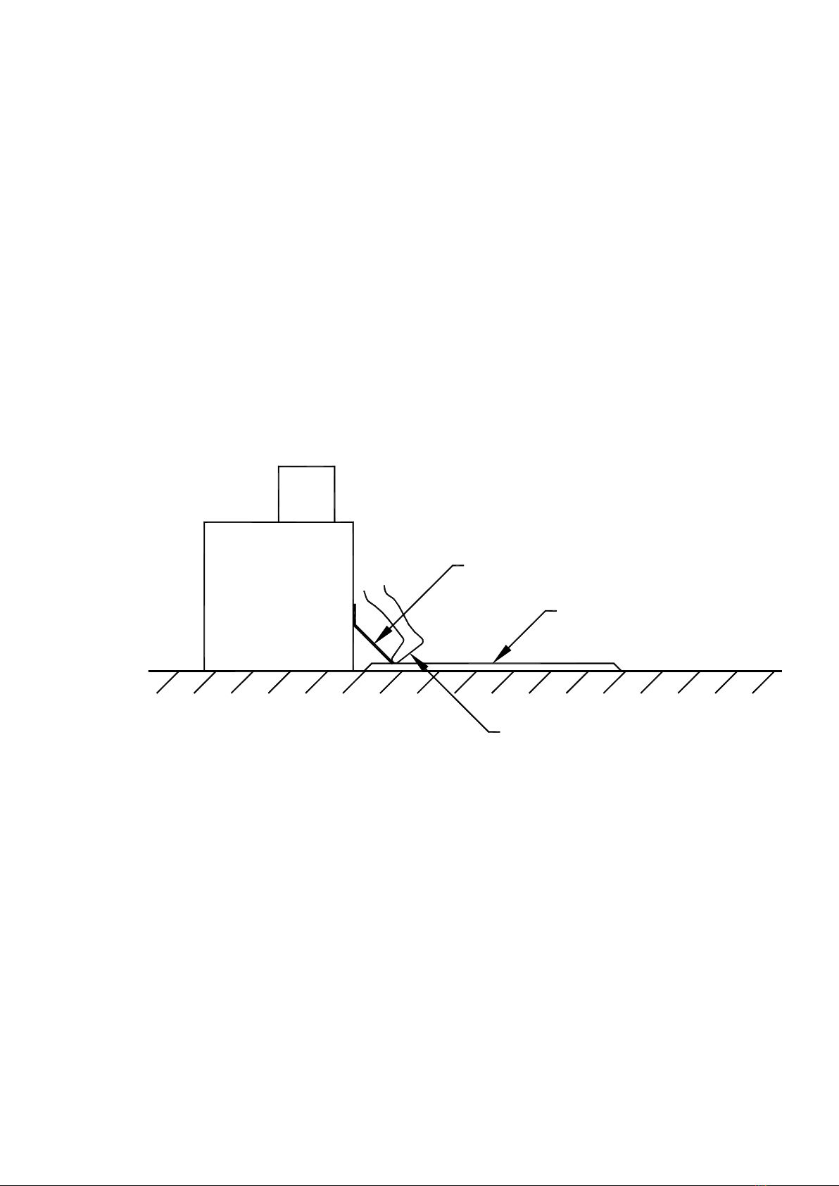
Ensurethatapersontip-toeingatthefrontof
themachinewillstillbestandingontheactive
area of the mat. See Figure 5.
(f) Wherever possible rectangular mats of
standard sizes should be used. Where this is
not possible, due to obstructions, mats with
edge or corner cutouts and even with holes
can be specified. This should only be done
where the obstructions are permanent.
9
(g) Under no circumstances should a mat
sensor be cut or drilled. It is not possible for
the user to modify the size or shape of a mat
sensor.
(h)Greatcareshouldbetakenwhenhandling
matsensors.Neverpickthesensorupordrag
it around using the cables. Never bend a mat
ataradiuslessthan300mm.Keepmatsensors
flatwheneverpossible.Alwaysstoreflat.Mat
sensors with one edge longer than 1 metre
should be handled by two people.
Figure 5 - Ensure operator is always standing on active area of sensor
(i)Afterinstallationthemachine/matsystem
must be commissioned in accordance with
section 5 of this manual.
(j) Any covers removed during installation
must be replaced as soon as possible.
SLOPING SKIRT FIXED TO MACHINE
MAT
OPERATOR ON TIPTOE ALWAYS
ON ACTIVE ZONE OF SENSOR
MACHINE

10
Figure 6 - AE-13 Sensor Edging
32 69
94
ø6
32
69 94
17
Figure 7 - AE-13 Sensor Edging
4.2 SENSOR INSTALLATION
4.2.1 SENSOR MOUNTING SURFACE
The surface on which the sensor is mounted
must be sound and reasonably flat. The
sensor can tolerate minor irregularities but
sharpedges orprojections greaterthan 1mm
maycauseprematuredegradation.Wherethe
surface is rough, cracked or breaking up, it
should be treated using proprietary sealing
and levelling compounds.
4.2.2 SENSOR FIXING
The sensor(s) must be fixed permanently in
position. Tapeswitch aluminium edging
AE-13shouldbe used aroundtheouter edge
ofthesensor.Thisspeciallydesignededging
comes in two parts, a base and a cover. The
cover provides a 20 degree ramp to prevent
a tripping hazard at the outer sensor edges.
TypeAE-13 edging is illustrated in Figure 6
and AE-C corner pieces in Figure 7. At the
junction of several mats, the mats should be
fixed to the floor using double sided tape.
4.2.3 INSTALLATION PROCEDURE
Step1-Planthelayout.Markoutonthefloor
the position and size of each sensor. Take
care to use the overall dimensions of mat
sensors.
Step 2 - Cut all edging to size. Remove any
burrs and sharp edges with a file.
Note: If AE-C corner pieces are used then:
the cut length = mat dimension - 12mm.
of AE-13
Step 3 - Mark the positions of the sensor
cables and cut slots in the inner face of the
edgingbaseextrusiontoallow accessforthe
sensor cables.
71
8
17
11
Figure 8 - AE-13 & AE-C Installation
NOTE: MAT SENSORS MUST BE
FITTED WITH THE LABEL SIDE UP.
Step4-Positionthebasesectionsaroundthe
mat and fit AE-C corner pieces. Drill pilot
holesthrougheach corner piece andholesin
thebasesectionsifapplicable. Removebase
sections/cornerpiecesanddrillandplugthe
floor. Refit base sections and corner pieces
and secure in position with the screws
provided, as shown in figure 8. Ensure the
cable exits neatly through the slot(s) in the
base section.
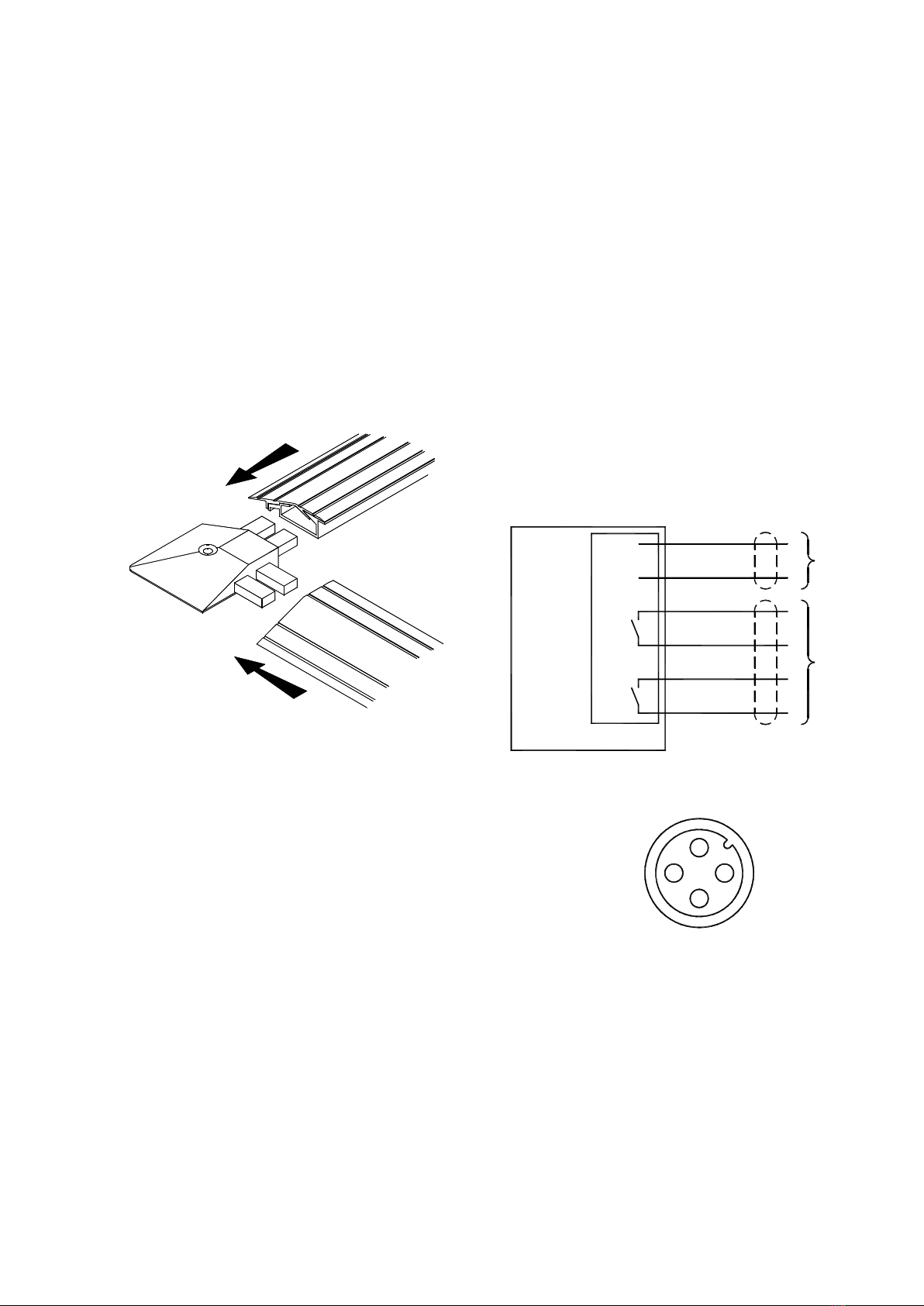
Figure 9 - CKP/Solo Connection Details
4.2.4 ELECTRICAL INSTALLATION
TheCKP/Solomatissuppliedwith2x4core
cables0.5mlong,eachcableisfittedwithan
M12 plug.Theconnectionstothematsensor
are shown in Figure 9.
Onecableisusedforthed.c.supply,andone
cableisusedforthe Volt-FreeSafetyOutputs.
NOTE: In order to achieve EN954-1
Category3safety integrity, theoutputs must
bewiredastwoseparatechannelstoasuitable
control capable of monitoring them for
equivalence.
Step 5 - Route the cable(s) to the interface.
The cable(s) should exit from the edging as
close to the interface position as possible.
The cables should be protected in suitable
conduitbetweentheedgingandtheinterface.
Protectanyedgesoverwhichthecablespass
withgrommetstrip orsimilar.
Step6- Fitthecoverextrusionof theedging
using suitable self-tapping screws.
+24V
0V
O/P
1
O/P
2
CKP/SoloSENSOR
BROWN
BLUE
BROWN
WHITE
BLUE
BLACK
1
3
1
2
3
4
CABLEB
CABLEA
2
4
31

12
5.PERIODICCHECKING
5.1GENERAL
Thefollowingsectionsdescribethe periodic
checks to be performed on a machine fitted
with a Tapeswitch safety mat system. If the
machineisfittedwithadditionalsafetydevices
the periodic checks prescribed by the
manufacturer of these devices should be
incorporatedintotheperiodiccheckingregime
described below.
If the machine fails any of the prescribed
checksthemachinemustbeisolatedandmust
notbeuseduntilthefaulthasbeenidentified
andrectified.
5.2 COMMISSIONING CHECKS
Thecommissioningchecksshouldbecarried
out by persons who are competent and who
have access to all the information supplied
with the machine and its safety equipment.
The results of the examination should be
recorded and copies of this record should be
kept by the user and the employer of the
personperformingtheexamination.
The person carrying out the examination
should,asaminimum,performthefollowing
checks:
(a) Check that the CKP/Solo is suitable for
usein theapplication:
(i)Checkthatthelevelofsafetyintegrity
providedbytheCKP/Soloissuitablefor
thelevelofriskpresentedbythe machine.
(ii)Checkthattheenvironmentissuitable
for the use of the CKP/Solo.
(b)Checkthatthedimensionsandpositionof
theCKP/Soloarecorrecttakingintoaccount
theoperatingmode.Forthispurposeitwillbe
necessarytochecktheoverallsystemresponse
timeusingadevicedesignedforthispurpose.
(c)Check that adequate measures have been
takentopreventaccesstothedangerousparts
ofthemachinefromanydirectionnotcovered
by the CKP/Solo.
(d) Examine the machine controls and
connections to the CKP/Solo to ensure that
therequirementsdescribedinthismanualand
inthemachine manual havebeenmet.
(e) Check that the CKP/Solo is fixed in
position and that no trip hazards are present
within the dangerous area.
(f) Exceptwherethedeviceis usedsolelyas
a trip device, check that it is not possible for
a person to stand in the dangerous area
without actuating the CKP/Solo.
(g) Check that it is not possible for the
dangerous parts of the machine to be set in
motion while the CKP/Solo is actuated.
(h) Check that actuation of the CKP/Solo
duringa dangerousphase ofoperationofthe
machineresults inthe dangerousparts being
arrested, or where appropriate, assuming an
otherwise safe condition, before any part of
a person could reach them.
13
(i) Check that, after the machine has been
stopped by the actuation of the CKP/Solo, it
is not possible for the dangerous parts to be
set in motion until the CKP/Solo has been
cleared, the reset button has been operated
and released, and the machine start control
has been re-operated.
(j)Checkthattheremovalofpowerfromthe
CKP/Solo prevents further operation of the
machine. It should not be possible for the
dangerous parts of the machine to set in
motion until power has been restored, the
reset button has been actuated and released,
and the machine start control has been
actuated.
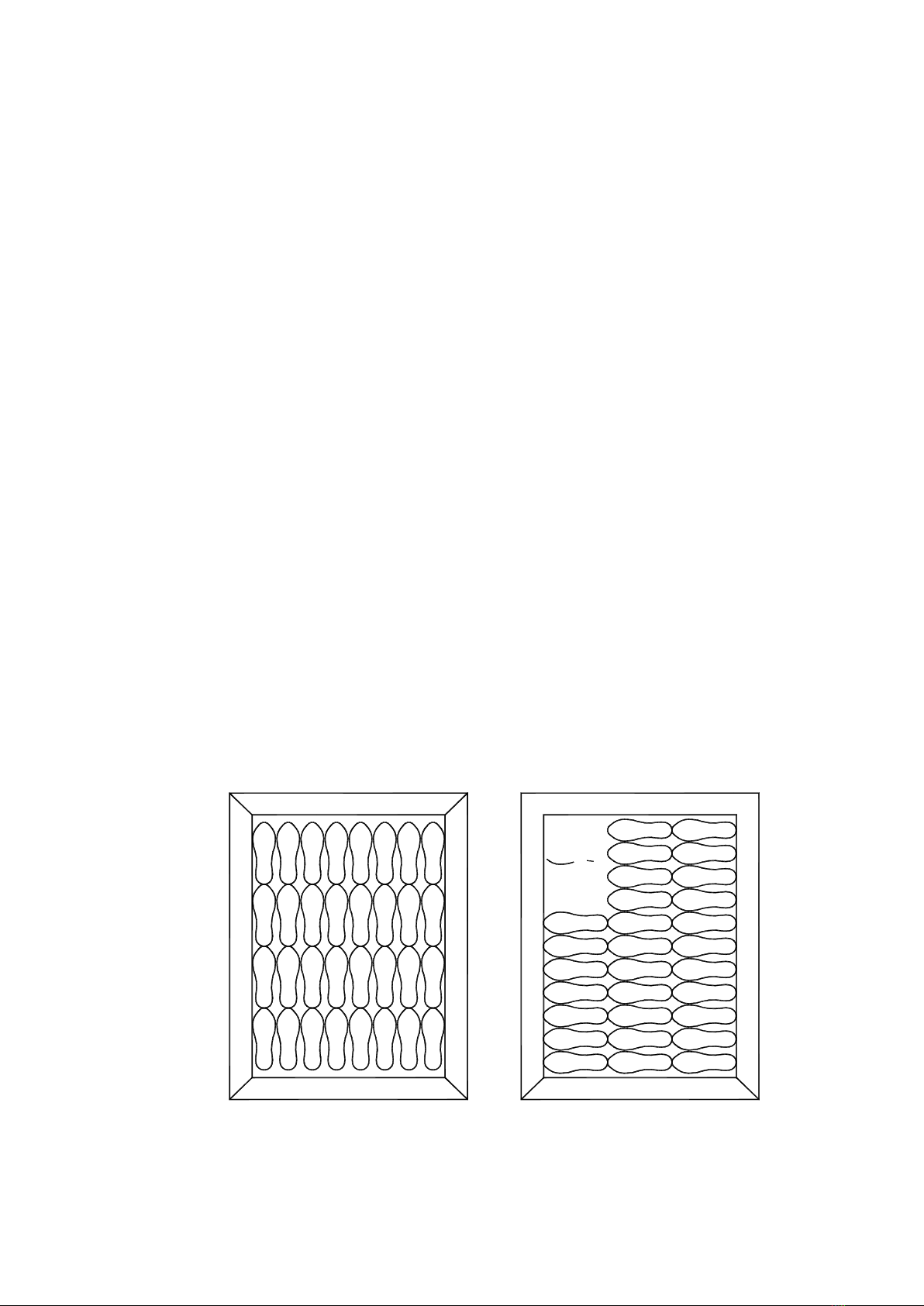
(k) Check that the CKP/Solo operates over
thewholeactiveareabywalking,‘heeltotoe’,
over the whole area in two directions, as
shown in Figure 10.
(l)Examinethestoppingperformancemonitor
(iffitted)toensurethatitisfittedandfunctioning
correctly.Ensurethatthemeansbywhichthe
stoppingperformancecanbeassessedbythe
operator is indicating correctly.
(m)Test the muting arrangements (if fitted).
Ensurethatthemutingisonlypossibleduring
non-dangerousoperationandensurethatthe
safetylevelofthemutingdeviceisatorabove
that of the safety mat but never below.
(n)Examinebrakesandclutches(iffitted)as
recommended.
NOTE: No stopping performance monitor
or muting facilities are provided with the
Tapeswitchsafetymatsystemandthereisno
means provided for the connection of such
devices to the system. These devices may
howeverhavebeenprovidedelsewhereinthe
machine control system.
Table of contents
Other Tapeswitch Lighting Equipment manuals


