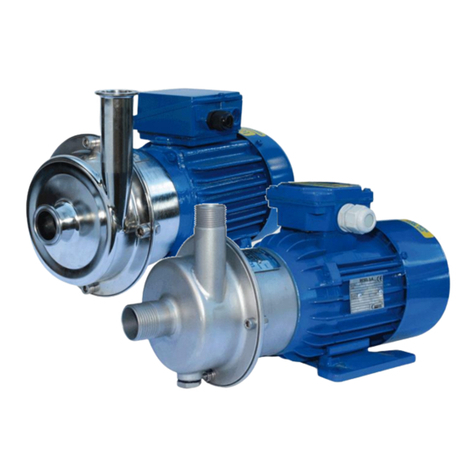
TapFlo CTM Series Programming manual
Other TapFlo Water Pump manuals

TapFlo
TapFlo CTM20-7 User manual

TapFlo
TapFlo CTV Series User manual

TapFlo
TapFlo Steinle Filter Press Pump Series Operation instructions

TapFlo
TapFlo SB Series User manual

TapFlo
TapFlo PTL P User manual

TapFlo
TapFlo CTX I User manual

TapFlo
TapFlo PTL Series User manual

TapFlo
TapFlo SG Series User manual
TapFlo
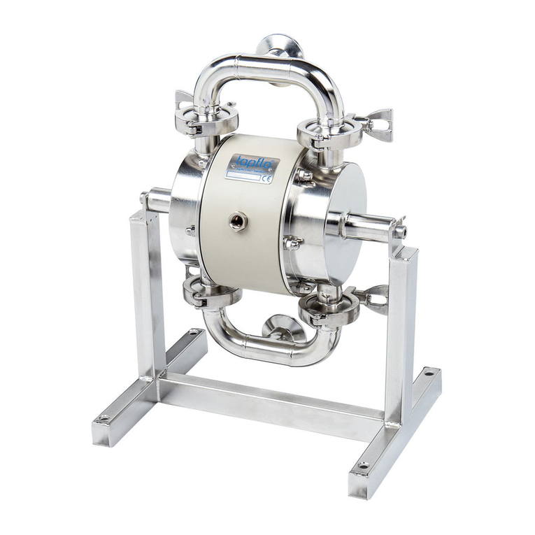
TapFlo sanitary T Series Programming manual
TapFlo
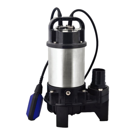
TapFlo SPT Series Operation instructions
TapFlo
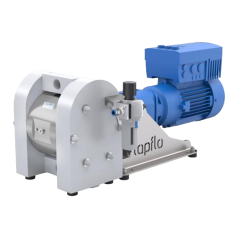
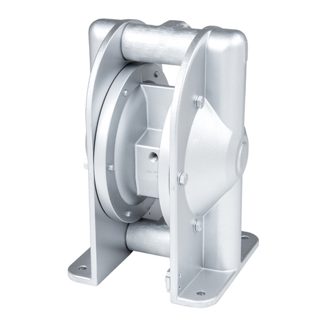
TapFlo TE Series Operation instructions
TapFlo
TapFlo Metal Series Operation instructions

TapFlo
TapFlo SF Series User manual

TapFlo
TapFlo SK Series User manual

TapFlo
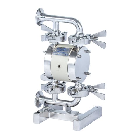
TapFlo CTV 40-13.5 User manual
TapFlo
TapFlo T/TX30 User manual

TapFlo
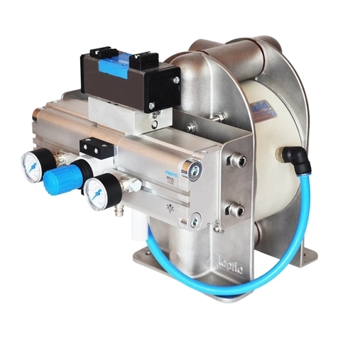
TapFlo CTS I User manual
TapFlo
TapFlo TF50 Operation instructions

TapFlo
TapFlo CTI AA-03 Operation instructions
TapFlo
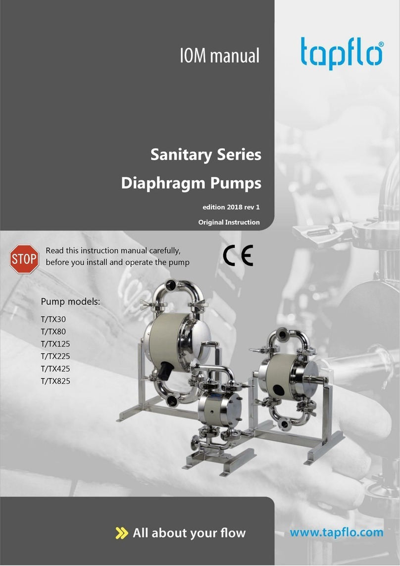
TapFlo Sanitary Series User manual
Popular Water Pump manuals by other brands

Watershed Innovations
Watershed Innovations HYDRAPUMP SMART FLEX Instructional manual

Graco
Graco Modu-Flo AL-5M instructions

Messner
Messner MultiSystem MPF 3000 operating instructions

Xylem
Xylem Bell & Gossett WEHT0311M Installation, operation and maintenance instructions

WilTec
WilTec 50739 Operation manual

Franklin Electric
Franklin Electric Little Giant 555702 HRK-360S instruction sheet

Ingersoll-Rand
Ingersoll-Rand PD02P Series Operator's manual

VS
VS ZJ Series Operating instruction

Flotec
Flotec FPZS50RP owner's manual

SKF
SKF Lincoln FlowMaster II User and maintenance instructions

Xylem
Xylem Lowara LSB Series Installation, operation and maintenance instructions

Water
Water Duro Pumps DCJ500 Operating & installation instructions

Action
Action P490 Operating instructions & parts manual

Flo King
Flo King Permacore Reusable Carbon Bag Disassembly. & Cleaning Instructions

ARO
ARO ARO PD15P-X Operator's manual

Pumptec
Pumptec 112V Series Operating instructions and parts manual

Virax
Virax 262070 user manual

Neptun
Neptun NPHW 5500 operating instructions


