Tapmaster 1780 User manual
Rev. 1.1
-4-
PH: 800-791-8117
FAX: 403-275-5928
Web: www.tapmaster.ca
E-mail: info@tapmaster.ca
Tapmaster Incorporated
3-1470 28th Street NE
Calgary, AB Canada
T2A 7W6
TROUBLE SHOOTING
FIVE YEAR LIMITED WARRANTY
Congratulations on your purchase of a TAPMASTER Hands Free Faucet Controller.
TAPMASTER products are thoroughly tested before shipment and are warranted to be free of de-
fects in material and workmanship for five years from the date of original purchase. The sole obli-
gation of Tapmaster Incorporated under the warranty is to provide replacement parts or at its op-
tion to repair the defective product or to provide the replacement product. Replacement parts
furnished in fulfillment of this warranty are warranted only for the unused portion of the original
warranty. Labor and shipping charges are not included.
Warranty conditions
- The five year warranty is subject to exclusions and limitations as stated be-
low:
Warranty extends only to defects which occur during normal use and intended applications and
does not extend to damage to products or parts resulting from alteration, repair, modification or
faulty installation. This warranty does not cover damage resulting from water borne debris or from
media other than clean potable water. Tapmaster
Incorporated makes no other express warranty on this product, all implied warranties including any
implied warranty of merchantability and fitness for a particular purpose are hereby disclaimed and
excluded. In no event shall
Tapmaster Incorporated be liable for special, incidental or consequential damages resulting from
the use of this
product or arising from breach of warranty or contract, negligence, loss of time, inconvenience or
loss of use of equipment.
OPERATION
To operate the Tapmaster simply step on the activator disk and open the faucet to the desired flow
and temperature. By stepping off the activator disk or releasing pressure shuts off the water flow
to the faucet. Once the faucet has been adjusted it should be left open. As in other foot operated
devices all operators should allow themselves some time to get accustomed to this unique method
of operation.
The use of short bursts of water as required will maximize water savings.
Figur
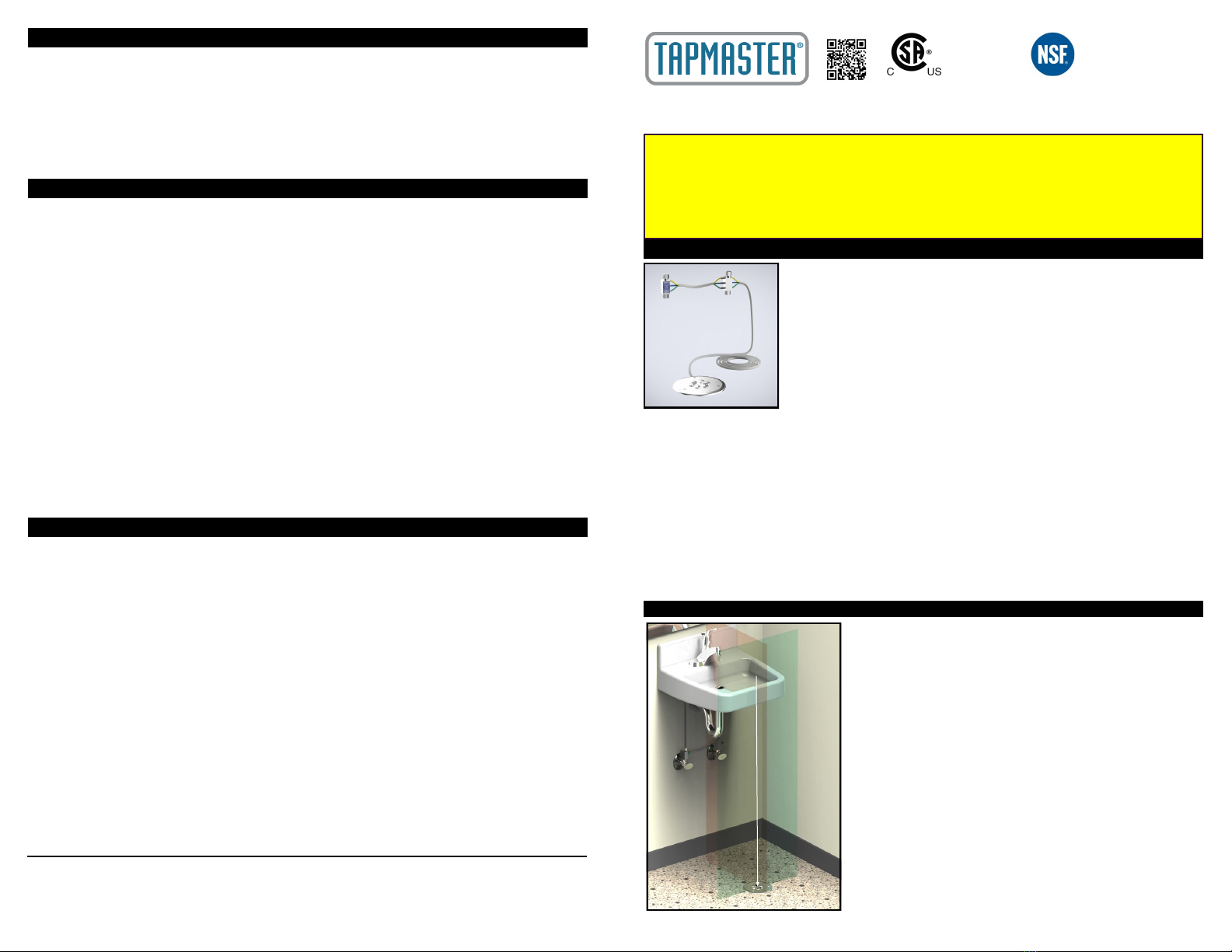
GENERAL
This illustration shows a typical Model 1780 Tapmaster. The valve blocks
connect in-line on the hot and cold water supplies with 3/8” O. D.
compression fittings. The pilot/actuator valve is mounted to the underside
of the activator disk which is mounted to the floor with the three #8 coun-
tersunk screws provided.
Model 1780, shown at left, features two in-line valve blocks, one each for
the hot and cold water lines and one step on activator disk. Model 1781
features one in-line valve block with one step on activator disk and is used
in situations where only one water line (typically tepid or recirculating
warm water systems) is required. Model 1782 is identical to Model 1781
with an additional activator disk added to permit water flow activation from
two separate locations as would be found in an island sink. Model 1784 is identical to Model 1780
with two in-line valve blocks and a second activator disk. Model 1786 features Hot/Warm/Cold
(HWC) temperature selection. Model 1788 is identical to Model 1786 except there are two HWC
disks.
Installation of the valve blocks will vary according to the application. In some cases it may be
simpler to connect the valve blocks at some mid-point along the 3/8" supply tubes. It will be
necessary to obtain a 3/8" x 3/8" compression connector
(available at most hardware stores)
to
connect the inlet fitting to the water lines. Other plumbing arrangements may be encountered
where larger than 3/8" O.D. tube size is used. In these situations reducing adapters
(available at
hardware stores)
must be obtained to permit installation of the Tapmaster.
Although Tapmaster will work with virtually any faucet, faucets that have handles which give a
visual reference for flow and temperature are recommended.
INSTALLATION INSTRUCTIONS: Models 1780, 1781, 1782,
1784,1786 & 1788
INSTALLING THE IN-FLOOR ACTIVATOR
GENERAL: The following instructions for installing the in-floor
activator are for a typical installation and only a guideline.
Whether it is a retrofit situation or a new facility install, sink
arrangements, floor coverings and construction materials will
vary greatly.
LOCATION: As per Figure 1, locate the center of the faucet/
sink and mark this location on the floor. Locate the leading
edge of the sink or counter and extend this line to the floor to
intersect the previously drawn center line. With the template
provided locate the activator disk in the center of this
position.
For new concrete floor installations, the in-floor activator
is design to fit into a standard round PVC "concrete pour type"
in-floor electrical box. These type of electrical boxes are
available from manufacturers such as Hubbel, LEW, Carlon
and Kraloy to name a few. PVC conduit is run from the in-
floor electrical box and out of the wall just underneath the
sink and above the water supply shutoff valves (see Figure 2
next page). After the PVC box is cut as per the manufacturers
instructions and the flooring placed, the Tapmaster activator
disk is ready to be installed.
Figure 1
Symptom Possible Cause Remedy
The hot or cold water is very slow
to turn on
Pinched tubing Check control tubing (yellow
and blue lines)
The hot or cold water is very slow
to shutoff or will not shutoff
Pinched tubing Check control tubing (green
and blue)
Noise from the Valve Blocks while
the water is running
The Valve Block may have
excessive debris trapped under
the Filter-screen
Service the Valve Blocks
Noise from the Valve Blocks when
turning water on and off
Air in the system Operate the pedal on and off
rapidly to clear air from the
valves.
PATENT NUMBERS
U.S. 5,505,227, 6,254,057,
6,382,585
Canadian 2,109,684
European 0654628
International & Other Patents
Pending
CSA-B125.1-18
ASME A112.18.1-2018
NFS/ANSI 61-2016
NSF/ANSI 372-2016
LOW LEAD CONTENT DRINKING WATER
For further information: www.tapmaster.ca or call 800-791-8117
CAUTION - READ BEFORE INSTALLATION
Tapmaster Incorporated will not be held liable for damage to property or persons resulting from improper installation of this product. If you are uncertain about
any part of the installation process, please contact us for assistance or consult a professional tradesperson before installation.
• Water lines must be flushed prior to installation
• Do not install if control tubes are damaged in any way
• Control tubes are pressurized after installation. Do not
expose tubing to excessive heat, unsealed chemicals, or
physical damage
• Use of substitute tubing voids manufacturer warranty and
liability
• Do not expose valves to thread sealants/plumbers putty
• Operating Range: 0 - 125 psi (8.6 bar) Max, 140° F
(60° C) Max

INSTALLING THE VALVE BLOCKS
STEP #2 - Apply a quality silicone caulking compound to the floor
side of the rubber gasket away from the activator disk.
(Warning;
Do not use excessive amount of caulking as this may glue the acti-
vator disk in place and make removal difficult should future service
be required)
With the #8 x 1” stainless steel countersunk screws
provided mount the activator disk to the finished floor. Use the
concrete anchors provided if required
(Model 1780 in-floor activators
are provided with regular #2 Phillips head screws or tamper-
resistant 5/32" center to center hole type screws upon request).
CAUTION DO NOT OVER TIGHTEN SCREWS particularly on
uneven floor coverings such as ceramic or porcelain tile. This may
damage the disk, cause it to warp and become unusable. Extra
caulking or mortar may be required to "bridge" uneven sections. If
the mounting service is exceptionally uneven use 3/16” ID washers
on the screws between the activator disk and floor to bridge the
gaps. The activator disk must be installed completely level and sta-
ble. If there are any questions or concerns in this or any other re-
gard please do not hesitate to contact us at 1-800-791-8117 and
ask for tech support.
Tapmaster valve blocks are connected in-line between the hot and cold
shut off valves and the faucet tubes as shown in Figure 2.
(Note:
The valve blocks are identical in function and may be used on either
hot or cold water lines. Position them according to how the control
tubing will be routed).
STEP #1 - Hook up the control tubes from the floor activator to the
valve block with the plastic sleeves provided as per the color-coded
arrangement in Figure 7.
(Note: To facilitate the installation of the
tubing and sleeves, dip the ends of the tubing into hot soapy water
and, using a pair of needle nose pliers, push the tubing on to the barb fittings. An adjustable
wrench opened to the diameter of the tubing will assist in pushing on the sleeves. Take care not
to damage the barb fittings or crush the tubes).
If a tube must be removed from a barb fitting,
split the tube along its length with a sharp knife
(Do not pull as this may damage the barb).
STEP #2 - Turn off the water supplies and place a bucket underneath the shut off valves to
catch water that may run out of the plumbing.
(Hint: Closing the faucet handles will minimize
leakage)
. Loosen the compression nuts on the riser tubes from the faucet at the shut-off valves. If
the faucet utilizes copper tube risers, bend and reposition the tubes in such a manner as to create
a 1-1/2" gap
(Do not kink).
To simplify the installation, replace the copper risers with flex risers
(available at most hardware stores)
. If this cannot be readily accomplished
the tubes will have to be shortened approximately 1-1/2”. Cut the tubes with
a tube cutter. If a tube cutter is not available a hacksaw may be used,
however be sure to de-bur and square the ends. Extra compression nuts and
sleeves are provided should the tubes need to be cut.
STEP #3 - Prior to installing the valve blocks, open the shut-off valves
momentarily to flush out any debris in the water lines. Large pieces of water
borne debris will be trapped by the filter/screen in the valve blocks and may
reduce water flow or cause noisy operation. As shown in Figure 8 connect
the valve block(s) with the integrated nut (input) to the shutoff fitting and the
faucet riser to the compression thread (output). Finger tighten only until both
valve blocks are in position. Be sure the plastic control tubing and fittings are
not damaged in any manner.
STEP #4 - Proceed to tighten the compression nuts using a 5/8” wrench on
the nut and a 7/8” wrench on the valve block body . Do not over tighten 3/8”
compression fittings with O-ring seals such as the valve block input
fitting. Hand tighten plus 1/2 turn with wrench.
STEP #5 - Verify that all connections are tight. Turn on the water supply
(s) and inspect all connections for leaks. Set the faucet, both hot and cold,
completely open and push the bar activator to start the water flow. Operate
the bar activator on and off rapidly to clear air from the valves. The valves
may experience some noise during on or off operation until the air is cleared.
Allow significant time to pass and then re-inspect all connections for leaks
(Small leaks may take several minutes to show up).
Figure 8
RISER
OUTPUT
INPUT
SHUTOFF
TUBE BUNDLES
MODEL 1786
SHOWN
The activator disk is
momentarily attached to
the optional PVC box
adapter ring (see Figure 3)
with the #8 x 1” stainless
steel countersunk screws .
PVC cement is applied to
the adapter ring, glued in
place and the activator disk
removed.
Retrofit installations will
vary according to the type
of floor, the availability, and
if any access underneath
the floor and the extent of
other renovations that may
be done in conjunction with
the Tapmaster install. For
example, for an "on-
slab" (concrete floor - no
under floor access) with a
floor covering replacement,
it would involve cutting a small trench to accommodate a
small diameter plastic or metal tube (eg:1/2" PEX, soft or rigid copper) routed up into the wall
underneath the sink through which the control tube bundle may be routed (see Figure 4). A
small pocket would also be cut into the concrete to accommodate the actuator valve on the
underside of the activator disk. The trench may be filled in , the floor covering installed and
finally the control tube bundle fished through the tube and the activator disk mounted to the floor
with concrete anchors.
In a situation where the floor covering, such as ceramic or porcelain tile is to be left in place, a
slot may be cut into the tile to accommodate the control tube bundle, routed into surface mount
plastic conduit for the wall, and the control tube bundle grouted into the floor (see Figure 5).
Another example of a retrofit installation would be a wood floor with access underneath (see
Figure 6). This situation would involve drilling a 2" (50mm) hole in the floor. Another hole
drilled through the floor to allow access into the wall and other to allow access through the wall
underneath the sink. (
Note: model 1786 HWC requires a 4" [100mm] hole to accommodate 2
actuator valves).
The control tube bundle is fished through these holes and the activator disk
mounted onto the floor with the template and screws provided.
Another example would be a concrete floor with access underneath. In this situation a may be
simpler to drill or core one
hole at the activator disk
location and another to
permit access into the wall
behind you and the sink. A
"U" shaped piece of conduit
or plastic pipe (depending on
local codes) could be
installed to allow the control
tube bundle to be fished
through underneath the sink.
This example is only one of
many possible solutions to
route the control tube
bundle.
STEP #1 Route the control
tube bundle through the
rubber gasket supplied and
route the control tube
bundle through the floor/wall
to the water line shutoff(s).
(see Figure 2 & 3 for PVC
box install and figure 4, 5 &
6 for retrofit install)
The control tube bundle may
be shortened . Be sure not to kink or damage the control
tubes in any way.
Figure 5
CONCRETE
ANCHORS (3)
SCREWS (3)
#8 x 1-1/4
CS
CONTROL
TUBE BUN-
DLE
THROUGH
SLOT CUT TILE
AND REGROUT
SCREWS (3)
#8 x 1-1/4 CS
INSTALLER SUPPLIED CAULKING
IN-FLOOR
ELECTRICAL
BOX
TUBE BUNDLE
ACTIVATOR DISK
Figure 2
PVC ELECTRICAL
BOX
PVC CONDUIT
Figure 4
POCKET CUT
INTO TILE/
CONCRETE
PIPE CUT INTO FLOOR
-2- -3-
Figure 7
Figure 3
Figure 6
This manual suits for next models
5
Other Tapmaster Bathroom Aid manuals


